Greenbridge ARI1128 Instruction Manual

ARI1128 & HP1128
Safety Relief Valve
THE GREENBRIER COMPANIES
One Centerpointe Drive, Suite 200
Lake Oswego, Oregon 97035
www.gbrx.com
INSPECTION &
MAINTENANCE BULLETIN
October 5, 2020
These instructions
are applicable to the
following models:
ARI1128
ARIHP1128
Only facilities with AAR Activity
Code C5 are certied to
recondition, repair, retest and
qualify tank car safety relief valves.
Personnel performing inspection
and test must be certied Level
I per AAR Manual of Standards
and Recommended Practices,
M-1002, Appendix T, 1.4.3.

1
October 5, 2020
New Valves for Replacement of Existing Equipment
New valves are tested, sealed and packaged at the time of manufacture. A new valve can be applied provided it is still in its original
packaging and tested within 6 months of the installation date. A valve with a test date older than 6 months must have the O-rings
replaced and retested.
Safety relief valves are spring loaded devices that can store a significant amount of energy. Assembly and disassembly
must be performed by trained, qualified personnel.
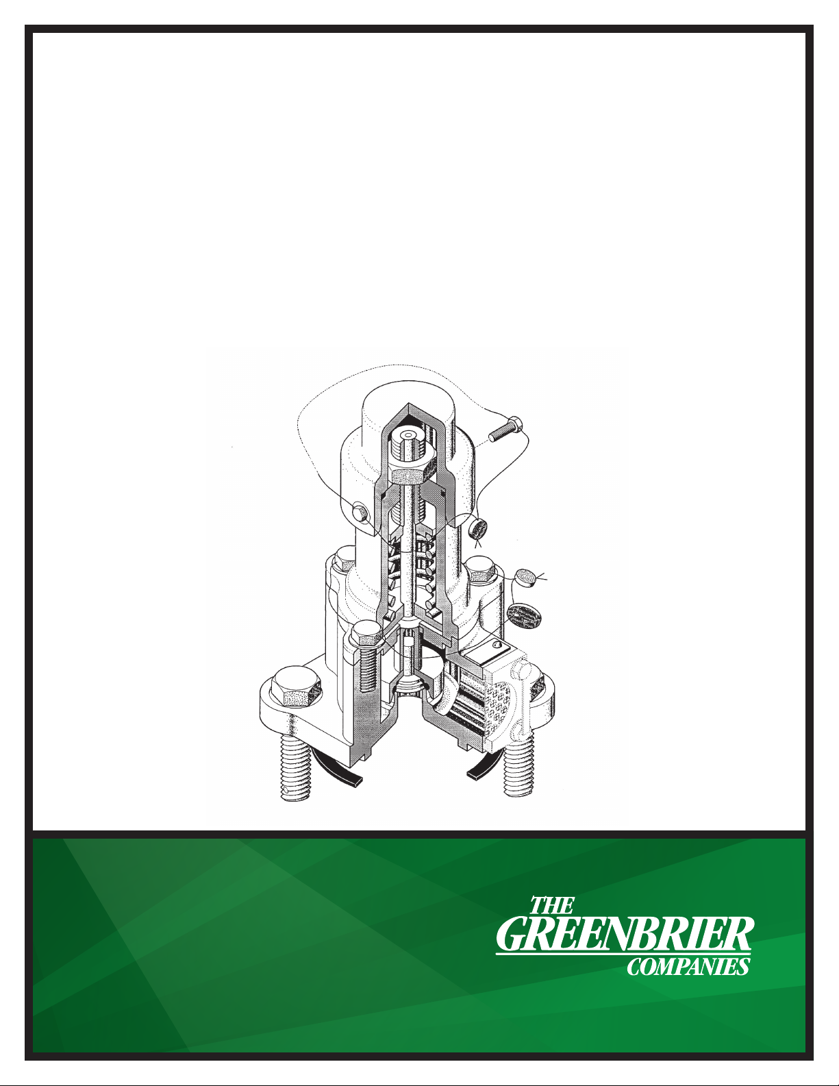
Disassembly Procedure
1. Remove the 2 seal wires, item #16.
2. Remove the two bolts securing the valve cover, item
#4, to the upper housing, item #2 then remove the
valve cover and the O-ring, item #21, taking care not to
mar the O-ring groove.
3. Measure and record the distance from the end of the
adjustment screw to the top of the jam nut, item #9.
This dimension will be used at reassembly.
4. Loosen the jam nut.
5. Loosen the spring adjustment screw, item #8 until
the spring, item #5, expands to a relaxed state. Some
spring tension will remain, see step #6. Remove the
adjustment screw.
6. Remove the three nuts, item #14, securing the upper
housing, item #1 to the valve body, item #2. This will
relieve the remaining spring force.
7. Lift off the upper housing, item #1, and lay on the
work bench. It may be necessary to loosen the upper
housing by tapping with a soft-faced hammer. Note:
Many of the components contained in the upper
housing may remain in place.
8. Remove the stem, item #10, the retainer, item #3, the
lower stem guide, item #7, the spring, item #5, and
the spring follower, item #6, from the bottom of the
upper housing.
9. Remove and discard the stem seal, item #22, from
the retainer, item #3, taking care not to mar seal
contact surfaces.
10. Reach inside the lower housing, item #2, and remove
the O-ring retainer, item #11, and the plug, item #12.
Push the plug out of the retainer.
11. Using a packing removal pick, remove the O-rings,
items #19 & 20 from the retainer taking care not to
mar the O-ring seating surfaces.

2
October 5, 2020
Inspection of Valve Components
Spring Adjustment Screw and Lower Stem Guide
The spring adjustment screw also serves as the upper stem guide. Inspect the threads for nicks, burrs and gouges. The threads can
be reestablished by chasing with a tread die. Excessive thread damage is grounds for replacement.
The stem should slide easily inside the spring adjustment screw and the lower guide. Visually inspect the stem, lower stem guide
and spring adjustment screw for signs of signicant wear. If wear is present, measure the contact surfaces of the stem and
the guides. The total clearance should not exceed 0.010”. If the clearance exceeds 0.010”, the stem and affected guide must
be replaced.
Valve Stem
Remove any scale or foreign material from the stem with a wire brush. Inspect the stem for signs of corrosion or pitting. Any
evidence of corrosion or pitting is grounds for replacement.
The stem must be inspected for cracking using either magnetic particle or dye penetration inspection methods. Cracking is
unacceptable. If found, the stem must be replaced.
Place the stem in a set of V-blocks and measure straightness with a dial indicator. The stem must be straight within .015 TIR. If out
of tolerance, the stem must be replaced. Straightening by bending or heat is not permitted.
O-Ring Retainer
Clean the O-ring setting surfaces inside the retainer with 400 grit emery cloth. Visually inspect the O-ring grooves. They must be free
of pits, corrosion or gouges that would prevent proper sealing of the O-rings.
Valve Body
The area around the valve seat must be free of debris, corrosion and foreign objects. Cleaning can be accomplished with a light
brush off blast using glass bead media. The seating surface must be free of nicks, burrs and gouges. The area should be cleaned and
lightly polished with 400 grit emery cloth. Any discontinuity that would prevent the valve from sealing is grounds for replacement.
Machining, grinding, welding or other alterations are not permitted.
Turn the valve body over to inspect the mounting ange and gasket surface. The gasket surface must be free from residual gasket
material, corrosion, nicks, burrs and gouges. Any discontinuity that would prevent sealing is grounds for replacement.
Valve Plug
Remove any scale, residue or foreign material from the plug with a wire brush. Inspect the stem for signs of corrosion or pitting. Any
evidence of corrosion or pitting is grounds for replacement.
Valve Spring
Remove all scale, residue and other foreign material from the spring with a wire brush. Inspect the spring for signs of corrosion or
pitting. Any evidence of corrosion or pitting is grounds for replacement.
The spring must be inspected for cracking using either magnetic particle or dye penetration inspection methods. Cracking is
unacceptable. If found, the spring must be replaced.
Stand the spring upright on a level surface. Place a straight edge against the outside and measure for straightness. Turn the spring
90 degrees and measure again. The spring must straight within ¼”. If out of tolerance, the stem must be replaced.
O-Rings
O-rings must be replaced any time the retainer is removed from the stem.

3
October 5, 2020
Assembly Procedure
1. With the valve body on its side, insert the valve stem through the top. Insert valve stem into body.
2. Place the valve in the press ensuring the spring is seated in the body and the stem is aligned. Install the spring and spring
follower then position the yoke, and compress the spring enough to apply the adjustment nut. With the nut fully engaged, further
compress the spring and tighten the nut to the previously recorded dimension from the nut to the end of stem.
3. Release the press and move the valve to the workbench.
4. Install the O-rings in the O-ring grooves of the O-ring retainer taking care not to tear, stretch or otherwise damage the O-rings.
Sharp tools should never be used for this operation.
5. Place the retainer with the O-rings on the stem.
6. Install the bumper washer on the retainer.
7. Install the locknut on the stem with a wrench applied to the hex on the retainer and one to the nut. Torque to 50 ±5 ft-lbs
8. Place the top guide over the studs and secure with the 4 nuts. Torque to 30 ± 5 ft-lbs.
9. Move the valve to the test stand.
10. After testing is complete, install the stem locknut and, using two wrenches, tighten to 30 ±5 ft-lbs.
11. Install new seal wires, item #17.
Guidelines for Testing and Adjustment
Determining Applicable Pressure Values
The ARI1128 safety relief valve is designed to operate at 75 psig. The start-to-discharge pressure (STD) must be 75 psig +/- 3 psig
and vapor-tight at 60 psig minimum.
The ARIHP1128 safety relief valve is designed to operate in a range from 225 psig to 330 psig. The start-to-discharge pressures
(STD) are as follows:
Start-to-Discharge Pressure (psig) Tolerance (psig) Vapor-Tight Pressure (psig)
225 6.75 180
247.5 7.4 196
255 7.7 204
280.5 8.4 224
300 9.0 240
330 10.0 264
Test Stand and Gauge Requirements
The test stand must have a mounting that complies with AAR M-1002, Section C-III, Appendix E, Figure E21 A. Test stand pressure
gauge must meet the requirements of AAR M-1002, Section C-III, Appendix D section 4.5, Test Gauge Standards. Gauges must be
date tagged.

4
October 5, 2020
Valve Leak Testing
1. Safety Relief Valve leak tests must be conducted in accordance with AAR M-1002, Section C-III, Appendix T. The inspector must
be Level I qualied or higher.
2. Apply the safety valve to the test stand.
3. Cycle the valve by applying shop air or nitrogen to the stand
4. Plug the valve body drain opening using putty or a foam ear plug. Fill the cavity to the top of the O-ring retainer.
5. Increase air pressure under the valve until the valve opens or “pops.”
6. Reduce pressure until the valve is closed and there are no bubbles present.
7. Rell the chamber and begin slowly increasing pressure under the valve until the rst bubble appears. This is the start-
to-discharge pressure (STD) and must be within the tolerances provided in the previous section, Guidelines for Testing
and Adjustment.
8. If the start-to-discharge pressure falls outside the specied range, adjust the valve spring by tightening the adjustment nut to
increase the discharge pressure and loosen to decrease. Repeat Steps 4-6.
9. NOTE: If adjusting the spring tension produces the opposite of the desired effect, the spring could be defective and must
be replaced.
10. Once the proper start-to-discharge pressure is attained, slowly decrease the pressure until the bubbles stop. This is the vapor-
tight pressure and must be within the tolerances provided in the previous section, Guidelines for Testing and Adjustment.
11. A vapor tight pressure falling below the specied minimum could indicate a problem with the O-rings not sealing properly.
Release all pressure from under the valve and remove the O-ring Retainer following the instructions under section, Disassembly
of the Top Guide and O-ring Retainer, steps 2-6. Visually inspect the O-rings for nicks, gouges or improper setting in the retainer.
Visually inspect the seating surface. A nger nail run across the surface can pick up discontinuities that are not readily visible.
Any defect must be corrected.
12. Once the start-to-discharge and vapor-tight pressures are attained, test a second time to conrm the settings then tighten the
stem locknut and install the seal wires per steps 10 & 11 in the Assembly Procedure section.
13. Mark the valve per AAR M-1002, Section C-III, Appendix A, Paragraph 7.1.2.
The undertaking of repair or replacement by the Purchaser, or its agents, without the expressed written consent of The Greenbrier Companies (GBX) shall void the
warranty and relieve GBX of all responsibility. Under no circumstances shall GBX be liable for any direct, incidental, consequential or other damages of any kind in
connection with the installation, operation, maintenance, repair, inspection or other use of any product purchased from it.
This manual suits for next models
1
Table of contents