Eaton’s Cooper Controls Business
203 Cooper Circle
Peachtree City, Georgia 30269
www.coopercontrol.com
Printed in Malaysia
PIR Sensitivity
1. Standindifferentareasoftheroomandwaveyourhands.
2. IftheRedLEDdoesnotturnON,checkforanyobstructions.
3. Standstillthreetofourfeetawayfromsensorforfiveseconds.LEDshouldnotturnON.
4. IfRedLEDturnsONwithoutmotionorisconstantlyONadjustPIRsensitivityto50%bymovingDIPSwitch5up.
Field-of-view outside the space
1. AdjustPIRsensitivityto50%bymovingDIPSwitch5up.
2. Usenon-reflectivetapestripstocovertheportionsofthesensorlensthatviewoutsidethespace.
Daylight Adjustments
ThedaylightingfeaturepreventsthelightsfromturningONwhentheroomisadequately
illuminatedbynaturallight.Ifthereisenoughlightintheroomregardlessofoccupancy,
thesensorwillholdthelightsOFF.Ifthereisnotenoughlightintheroom,thesensorwill
allowthelightstoturnONwhenoccupied.Thesensorwillnotallowthedaylightingfeature
toturntheloadOFFuntilthespaceisvacantorthelightlevelrisesabovethesetpointand
theTimeDelayexpires.WhileinManualActivationMode,ifsomeoneattemptstoturnthe
loadONandthereissufficientdaylightavailabletheDaylightingfeaturewillholdthelights
OFF.
1. Setthelightlevelwhentheambientlightisatthelevelwherenoartificiallightis
needed.Ifthisfeatureisnotneeded,leavethelightlevelatmaximum(fullyCW).
2. Withtheload(s)ON,putthesensorintoTestMode.ToplaceintoTestMode,toggle
DIPSwitch8outofitscurrentposition,wait3secondsandthenbackintoits
originalposition.
3. SettheLightleveltominimum(fullyCCW).
4. LetthesensorTime-outsolightsareOFF.Enterthespaceandlightsshouldremain
OFF.
5. Makesurenottoblockthesensorfromthedaylightsourceandadjustthelightlevel
potentiometerCWinsmallincrements.(Pause5secondsbetweeneachadjustment).
6. LightswillnotturnONuponoccupancyactivation,whentheambientlightlevelexceedsthedaylightthresholdsetting.
Time Delay Adjustments
Peoplewhoremainverystillforlongperiodsoftimemayneedalonger
TimeDelaythanthedefaultsettingof10minutes.Aslongastheself-
adjustingfeatureisenabled,theswitchwillrespondtoeachpairofFalse-offs
withnonormalOFFinbetween,byalternatelymakingslightadjustmentsto
eitherTimeDelay(by2minuteincrements)orsensitivity,sothereshould
benoneedformanualadjustment.Ifmanualadjustmentisdesired,referto
TimeDelaysettingsinDIPSwitchlegend.
ResetsensorTimeDelaytofactorysettingsbymovingDIPSwitches1and
2down.(IfDIPSwitches1and2arealreadydown,toggleDIPSwitch1out
ofitscurrentposition,wait3seconds,andthenbacktoitsoriginalposition).
Override
Theoverridesettingallowsthesensortooperateasaserviceswitchintheunlikelyeventoffailure.
1. MoveDIPSwitch8up.
2. ThePushbuttoncanbeusedtomanuallyturnlightsONorOFF.
Warranties and Limitation of Liability
DIP Switch Settings
Troubleshooting
Pleaserefertowww.coopercontrol.comundertheLegalsectionforourtermsandconditions.
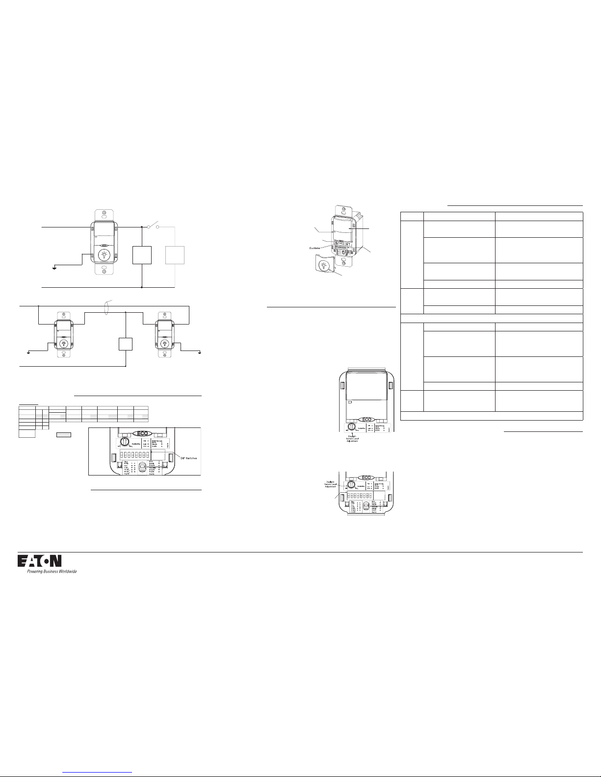
Checkout and Adjustment
120/277 VACBLACK BLUE
NEUTRAL
GROUND
GREEN
LOAD 1 LOAD 2
LOAD 1
BLACK BLUE
NEUTRAL
THREE-WAY WIRING DIAGRAM:
LIGHTS WILL TURN OFF, WHEN UNIT THAT WAS TURNED ON LAST AND/OR DETECTEDMOTION LAST TIMES-OUT.
GROUND
GREEN
120/277 VAC
BLACK
BLUE
GROUND
GREEN
TRAVELER
WIRES
Wiring Diagram 3: 120/277 VAC single level single circuit three-way wiring diagram
Wiring Diagram 2: 120/277 VAC single level switch dual level wiring using a toggle switch wiring diagram
5 Minutes
Auto*
*Self-Adjusts to
10 min. user mode
Time Delay
DIP Switch
Activation PIR Sensitivity Override
Relay 1
Not Used EcoMeter
Walk-Through Mode
Default =
30 Minutes
15 Minutes
12
DIP Switch Legend
6
Disable
Enable
43
Auto
Manual
5
Full
50%
8
7
Enable
Disable
Disable
Enable
12345678
AdjustmentsshouldbemadewiththeHVACsystemonsothattheinstallerwillbeabletodetecttheeffectofairflowon
theoperationoftheONW-P-1001-MV.Useonlyinsulatedtoolstomakeadjustments.
Immediatelyafterapplyingpowertothelightingcircuit,waitapproximatelytwominutesfortheswitchtopowerup
andstabilize.
Self-Adjust
Sensorisshippedinself-adjustmode.ThisappliestoTimeDelayandPIRsensitivity.InpreparationfortheInstallerTest,
theTimeDelayissetto15seconds,afterthesensorisinstalled,poweredONandhasstabilized,theunitwillTime-out15
secondsafterthelastmotiondetected.CoverageandsensitivitycanbeconfirmedbywatchingtheRed(PIR)indicatorLED
onthefrontofthesensor,whilemovingaroundtheroom.
1. WalkaroundtheroomandmonitorLEDs.
2. Standindifferentpartsoftheroomandwaveyourhands.
LEDshouldonlyturnONforonesecondwitheachmotion.
(IfLEDdoesnotturnON,gotoInstallerAdjustments–
SensitivityAdjustmentSection)
3. Standstillthreetofourfeetawayfromsensorforfive
seconds.LEDshouldnotturnON.(IfLEDturnsON,goto
InstallerAdjustments–SensitivityAdjustmentssection)
4. Walkoutsidetheroomandwait15secondsforthelights
toturnOFF.(IflightsdonotturnOFFgotoInstaller
AdjustmentsSection)
5. Re-entertheroomtoactivatesensor.(Iflightsdonotturn
ONgotoTroubleshootingSection)
6. Atthispointyoucanreattachthepushbuttonandexit
theroom.Whenthesensortimes-outandisOFFforfive
minutes,theunitwillgotoa10minuteTimeDelayuser
modesetting.
Note:ToplaceintoTestMode,toggleDIPSwitch8outofitscurrentposition,wait3seconds,andthenbackintoitsoriginalposition.
ON/OFF Button
PIR Lens
DIP Switches
Daylight
Sensor Level
Adjustment
Red (PIR)
Detection LEDs
12345678
DIP Switches
1 & 2
Issue Possible Causes Suggestions
Lights
Will Not
Turn ON
automatically
SensorisinManualONmode PressPushbutton.IfAutoMode
isdesiredchangeActivationModetoAuto.
SensorwasturnedOFFmanually.IftheSensor
wasturnedOFFmanuallybeforetheTimeDelay
expired,lightswillremainOFFfortheremainder
oftheTimeDelay.
CheckEcoMeterLED.IfLEDisONthisis
anindicationthatthelightswereturnedOFFmanually.
PressthePushbuttontoturnthelightsbackON.
DaylightFeatureEnabled IfalllightsarerequiredtoturnON
adjustdaylightpotentiometer.
Powerinterruption Checkincomingvoltageand/orwiring.
Lights
Will Not
Turn ON
manually
DaylightFeatureEnabled IfalllightsarerequiredtoturnON
adjustdaylightpotentiometer.
Powerinterruption Checkincomingvoltageand/orwiring.
If lights will still not turn ON, set sensor to override mode and call Technical Services at 1-800-553-3879
Lights
Will Not
Turn OFF
automatically
Override MakesuresensorisnotinOverrideMode(DIPSwitch8up).
Self-Adjust
IfsensorisinSelf-AdjustMode,itmaybepossibleforthe
unittohaveincreasedtheTimeDelaytoa30minutedelay.
IfthelightsdonotturnOFFafter30minutesfollownextstep.
30MinuteDelay
MaximumTimeDelayis30Minutes.CheckDIPSwitches
toverifyDIPSwitchsettings.IflightsdonotturnOFFatthe
setTimeDelay,checknextstep.
PIRactivatedbyheatsourceotherthanoccupant MoveDIPSwitch5up.
Lights
Will Not
Turn OFF
manually
CallTechnicalServices
If lights will still not turn OFF, call Technical Services at 1-800-553-3879
CAUTION: If a room is wired for two circuits using two separate hot leads, it is very important to connect only
one circuit per relay. Both circuits must be fed from the same phase.
Installer Adjustments