Limited Warranty
DIP Switch Settings Troubleshooting
All products manufactured by Cooper Controls and identified with the Greengate brand are warranted to be free from defects in
material and workmanship and shall conform to and perform in accordance with Seller’s written specifications for a period of: Five
(5) years from date of shipment for all occupancy sensors and Three (3) years from date of factory invoice for our hardware and
software on Lighting Control Panels. We warranty all our standard relays for a period of 10 years from date of factory invoice. We
guarantee the performance of our system to specifications or your money back. This warranty will be limited to the repair or
replacement, at Seller’s discretion, of any such goods found to be defective, upon their authorized return to Seller. This limited
warranty does not apply if the goods have been damaged by accident, abuse, misuse, modification or misapplication, by damage
during shipment or by improper service. There are no warranties, which extend beyond the hereinabove-limited warranty,
INCLUDING, BUT N T LIMITED T , THE IMPLIED WARRANTY F MERCHANTABILITY AND THE IMPLIED WARRANTY F FITNESS.
No employee, agent, dealer, or other person is authorized to give any warranties on behalf of the Seller or to assume for the Seller
any other liability in connection with any of its goods except in writing and signed by the Seller. The Seller makes no representa-
tion that the goods comply with any present or future federal, state or local regulation or ordinance. Compliance is the Buyer’s
responsibility. The use of the Seller’s goods should be in accordance with the provision of the National Electrical Code, UL and/or
other industry or military standards that are pertinent to the particular end use. Installation or use not in accordance with these
codes and standards could be hazardous.
Cooper Controls
203 Cooper Circle, Peachtree City, GA 30269
800-553-3879
www.coopercontrol.com
P/N 9850-000174-01
Checkout and Adjustment
Issue Possible Causes Suggestions
Lights
Will Not
Turn ON
automatically
Wall Switch FF Turn Wall Switch N.
If low voltage switch option is used, lights may
have been turned-off manually. Press low-voltage switch.
Daylight Feature Enabled If all lights are required to turn N adjust DIP Switch 10
and/or daylight potentiometer
Power interruption Check incoming voltage and/or wiring
Lights
Will Not
Turn ON
manually
Daylight Feature Enabled If all lights are required adjust DIP switch 10 and/or daylight
potentiometer.
Power interruption Check incoming voltage and/or wiring
If lights will still not turn ON, set sensor to override mode and call Technical Services at 1-800-553-3879
Lights
Will Not
Turn OFF
automatically
verride Make sure sensor is not in verride Mode (DIP Switch 8 up).
Ultrasonic Sensitivity set High Lower sensitivity by turning green potentiometer CCW in
small decrements.
Sensor installed close to an air vent Sensors should be installed minimum 4 - 6 feet away from
any air vent and out of path of heavy airflow.
Sensor installed close to indirect lighting. Sensors should be mounted away from indirect lighting.
Self-adjust
It may be possible for the unit to have self-adjusted the time
delay to a 30 minute delay. If the lights do not turn FF after
30 minutes follow next step.
30 Minute Delay Maximum time delay is 30 Minutes. Check DIP Switches to
verify DIP Switch settings. If lights do not turn FF at the set
time delay, check next step.
PIR activated by heat source other than occupant Move DIP Switch 5 up.
Bypass Check wiring to make sure sensor or switchpack are not
bypassed.
Lights Will Not
Turn OFF
manually
verride Make sure sensor is not in verride Mode (DIP Switch 8 up).
If lights will still not turn OFF, call Technical Services at 1-800-553-3879
LED Indicators Functionality
Adjustments should be made with the HVAC system N. Use only insulated tools to make adjustments.
Self-Adjust
Sensor is shipped in the Self-Adjust Mode. This applies to Time Delay, US, and PIR sensitivity. In preparation for
the Installer Test, the time delay is set to 15 seconds, after the sensor is installed, powered- N and has stabilized,
the unit will Time-out 15 seconds after the last motion detected. Coverage and sensitivity can be confirmed by
watching the Green (US) and Red (PIR) indicator LEDs on the front of the sensor, while moving around the room.
1. Walk around the room and monitor LEDs. LEDs should only turn N for ¼ second with each motion. (If LEDs
do not turn N, go to Installer Adjustments - Sensitivity Adjustments Section)
2. Stand still six to eight feet away from the sensor for five seconds. LEDs should not turn N. (If any LED turns N,
note LED and go to Installer Adjustments – Sensitivity Adjustment section)
3. Walk outside the room and wait 15 seconds for the lights to turn FF. (If lights do not turn FF go to Installer
Adjustments Section)
4. Re-enter the room to activate sensor. (If lights do not turn N go to Troubleshooting Section)
5. The unit will remain in Test Mode for 10 minutes then automatically exit Test Mode and go for 10 min. Time
Delay User Mode setting.
Note: To place into Test Mode, toggle DIP Switch 10 out of its current position, wait 3 seconds, and then back in to its original position. To force into
10 min User Mode move Dip Switches 1 and 2 down. (If DIP Switches 1 and 2 are already down, toggle DIP Switch 1 out of its current position, wait 3 sec-
onds, and then back to its original position) While in Test Mode, the LEDs will flash once per 1/4 second.
Sensitivity Adjustments
Ultrasonic Sensitivity (Green LED) – Using a small flathead screw driver turn the green potentiometer so that the arrow
points up.
1. Stand in different areas of the room and wave your hands.
2. If the Green LED does not turn N, increase the US sensitivity by turning the green potentiometer clockwise in
small increments. Repeat Step 1.
3. Stand still six to eight feet away from sensor for five seconds. LED should not turn N.
4. If Green LED turns N without motion or is constantly N decrease the US sensitivity by turning the green poten-
tiometer counter-clock-wise in small decrements. Repeat Step 3.
PIR Sensitivity
1. Stand in different areas of the room and wave your hands.
2. If the Red LED does not turn N, check for any obstructions.
3. Stand still six to eight feet away from sensor for five seconds. LED should not turn N.
4. If Red LED turns N without motion or is constantly N adjust PIR sensitivity to 50% by moving DIP Switch 5 up.
Field-of-view outside the space
1. Adjust PIR sensitivity to 50% by moving DIP Switch 5 up.
2. Adjust Ultrasonic Sensitivity.
Daylight Adjustments (-R Model Only 0 to 300 foot-candles)
If this feature is not needed, leave the light level at maximum (fully clockwise).
The Daylighting feature prevents the lights from turning N when the room is adequately illuminated by natural light. If
there is enough light in the room regardless of occupancy, the sensor will hold the lights FF. If there is not enough light
in the room, the sensor will allow the lights to turn N when occupied.
Full and Half Logic Modes (See DIP Switch legend):
In both Full and Half Logic modes, lights connected to the yellow control lead will not turn N upon occupancy acti-
vation, should the ambient light level exceed the preset foot-candle level.
After activation:
Full Logic Mode - should the ambient light level exceed the preset foot-candle level, the lights connected to the yel-
low control lead will turn FF. The lights will remain FF, until the ambient light level falls below the set point.
Half Logic Mode – the output state of the yellow control lead will not change with ambient light changes, after occu-
pancy activation. If the amount of natural light available rises above the setpoint, the daylight sensor will not turn the
lights FF while occupancy is being detected.
Note: Set the light level when the ambient light is at the level where no artificial light is needed. In order for this fea-
ture to function, the yellow control lead must be wired.
1. With the load N, put the sensor into Test Mode. To place into Test Mode, toggle DIP Switch 10 out of its current
position, wait 3 seconds and then back in to its original position.
2. Set DIP Switch 10 to Full or Half Logic Mode.
3. Set the Light level to Minimum (fully CCW).
4. Leave the room and let the sensor Time-out so lights are FF. Enter the space and lights should remain FF.
5. Make sure not to block the sensor from the daylight source and adjust the light level potentiometer CW in small
increments until the lights are N. (Pause 5 seconds between each adjustment)
6. nce the lights are N, the load connected to the sensor will not turn N if light levels are above the current
illumination.
Time Delay Adjustments
People who remain very still for long periods of time may need a longer Time Delay than the default setting of 10 min-
utes. As long as Auto is enabled, the sensor will respond to each pair of False-offs with no normal FF in between, by
alternately making slight adjustments to either Time Delay (by 2 minute increments) or sensitivity, so there should be no
need for manual adjustment. If manual adjustment is desired, refer to Time Delay settings in DIP Switch legend.
Reset sensor Time Delay to factory settings by moving DIP Switches 1 and 2 down. (If DIP Switches 1 and 2 are
already down, toggle DIP Switch 10 out of its current position, wait 3 seconds, and then back to its original position)
Automatic Mode
In Automatic- N Mode, the lights turn N when a person enters the room. If optional momentary low voltage switches
are used along with Automatic- N Mode, activating the switch(es) while the load is N turns the load FF. When the
load is turned FF manually, as long as the sensor continues to detect occupancy the loads stay FF. After the Time
Delay expires, the lights stay FF and the sensor goes back to Automatic- N Mode. For wiring information for the
optional momentary low voltage switch(es), please see the wiring section of the installation instructions.
Manual Mode (-R Model Only)
In Manual- N Mode, the optional momentary low voltage switch(es) is required to turn the load(s) N. nce activated
the sensor will maintain the lights N until motion ceases and the Time Delay expires. While the room is occupied the
BAS relay remains active. After the Time Delay expires, the load(s) will automatically be turned FF and the switch(es)
must be used to turn the load(s) N unless there is motion detected within the 10 second re-trigger period.
Lighting Sweep Option
If selected, this DIP Switch option forces an initial 60 second delay upon “power up” to prevent false activation in
buildings with computer control systems.
1. Move DIP Switch 9 up. If not selected (Dip Switch 9 down), upon initial “power up” or restoration of power the sen-
sor will force the lights N no matter the state of occupancy.
H AC/Tracking Mode (-R model only)
If selected, Tracking Mode allows the load connection to the Form C relay to follow the state of the sensor’s blue lead.
HVAC Mode allows the load connected to the Form C relay to remain N when the lights are turned FF manually.
Applications may include keeping the room at a desired temperature while giving a presentation and the lights are FF.
Zero Time Delay Mode
In Zero Time Delay Mode, the output is actuated for one second to signal another device that the space being moni-
tored is occupied. Applications may include the use of a lighting control system to manage the delay of the lighting deac-
tivation. Please see the wiring diagram section for wiring details.
When in Zero Time Delay Mode and Tracking Mode the load connected to the Form C relay shall follow the state of
the sensor’s blue lead (zero Time Delay for the form C relay).
When in Zero Time Delay Mode and HVAC Mode, the load connected to the Form C relay remains N for the standard
Time Delay.
Override
The verride setting allows the lights to remain N in the unlikely event of sensor failure.
1. Move DIP Switch 8 up.
While in verride Mode, the optional low voltage momentary switch(es) will toggle the lighting load(s).
Printed in Malaysia
Installer Adjustments
(-R model only)
SweepOverride
LEDs
(-R model only)
(-R model only) (-R model only)
Full/Half Logic HVAC/Tracking Zero Time Delay
Pot 1 - Blue (0-300 FC)
Ultrasonic
(-R model only)
Pot 2 - Green
During Installer/Test Mode
LEDs will flash once per ¼ second LEDs will flash once per second
While in User Mode
10 to 30 minutes
LED Flashing Speed
Duration 10 minutes
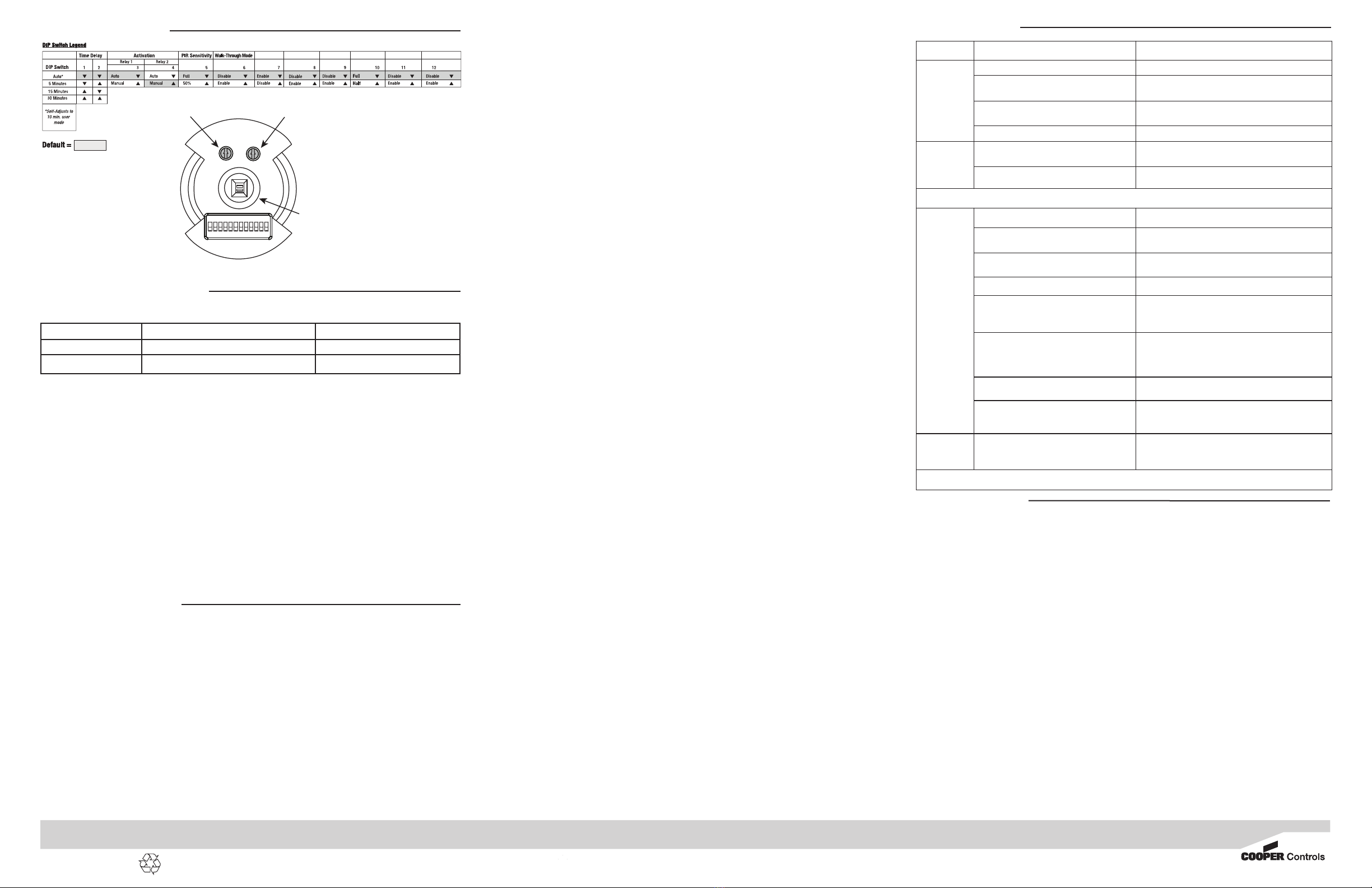
12345678910 11 12
ON
Daylight Sensor Adjustment Ultrasonic Sensitivity Adjustment
PIR Detector


