Greengate PPS-4 Assembly instructions

The Indoor Contact Input Photosensor (PPS-4) can be used
with any Greengate lighting controller and may also be used
in conjunction with Greengate Switchpacks and BAS version
motion sensors for daylight harvesting.
The operating range of the photosensor is 1 to 1400 foot-
candles. It should be placed indoors only and works optimally
within the temperature range of 50º to 104º F.
The photosensor is powered directly from the Greengate
Lighting Controller 24VDC peripheral power terminal or from
a Greengate Switchpack.
The photosensor has an automatic deadband feature. From
the user selected ON threshold which can be set at points be-
tween 1-850FC, the photosensor allows a 25%, 50%, 75% or
100% deadband. In addition to the deadband, the photosensor
allows an OFF time delay to prevent nuisance cycling.
Getting Started
1. Do not discard these installation instructions. Please
keep for future reference and operation information.
2. It is recommended that all low-voltage wiring be done with
power removed to the logic board to protect components
from potential shorts during the wiring process.
3. Use only as intended and at the listed voltage.
4. All installation and service must be performed by
qualiedpersonnelorservicetechnicians.
5. Install in accordance with the National Electrical Code
and any other codes which may apply.
6. Installation and wiring information contained in this
document is based on industry-accepted standards
andpractices.Ifconictsexistbetweentheseinstructions
and any applicable codes or ordinances, please contact
Greengate before proceeding with the installation.
7. High voltage is present inside the lighting enclosure.
Useextremecautionwhenperformingmaintenanceon
this equipment.
8. Document all wiring and device terminations and
locationssothatdevicescanbeproperlycongured
and programmed for operation.
Mounting Detail
When performing daylight harvesting, choice of the mount-
ing location for the photosensor is the key to success. It is
important to choose a location that is representative of the
day-lighting in the area being controlled. Shadows should
also be taken into account as they will affect the day-lighting
application.
The photosensor has been provided with a threaded mounting post
and washer and lock nut to allow connection through a ceiling tile.
The mounting post may be removed by squeezing it near the
base of the PPS-4. This allows it to be mounted using the two
screw holes under the cover. Use two #6 pan head screws that
are appropriately length for the mounting location. This type
of mounting may be used for sheetrock locations.
Window Application
When used in a window application, the PPS-4 should be located
within 12 feet of the window and away from any direct light from
controlledxtures.Ideally,locatingthephotosensorbetweenthe
windowandrstrowofxturesisrecommended.RotatethePPS-4
so that the light sensor is nearest the window.
Skylight Application
There are two options for mounting a sensor that will be looking
at contributed light from a skylight. It is important that the sensor
be mounted such that it is not looking at direct sunlight as this will
causethesensortoexceedthemaximumofitsrange.Toprevent
this, locate the sensor either on the South wall of the skylight well
looking North (sensor should be rotated so that the sensor’s eye
isatthetop)ormountontheceilingnexttotheskylightlooking
downattheoor(sensorshouldberotatedsothatthesensor’s
eye is closest to the skylight well).
Wiring Detail
Cooper Controls
203 Cooper Circle, Peachtree, GA 30269
800-553-3879
www.coopercontrol.com
Indoor Contact Input Photosensor
INSTALLATION SHEET
Model# PPS-4
General Information
Cooper Controls
203 Cooper Circle, Peachtree, GA 30269
800-553-3879
www.coopercontrol.com

Figure-5: ControlKeeper 4 Connection
Figure-4: ControlKeeper T Connection
Figure-3: LiteKeeper 4 Connection
All low-voltage wiring is Class 2 wiring. All low-voltage wiring must
be run in separate conduit from line-voltage wiring. Failure to sepa-
rate high-voltage from low-voltage wiring may cause interference
with lighting controller or motion sensor function. Low-voltage wir-
ing must enter the Greengate lighting controller enclosure through
the low-voltage section of the enclosure.
Cabling should be 18 AWG twisted, three-conductor, unshielded
cable.Maximumlengthfordrycontactclosuredevicewiringis
1000 feet.
Wiring the PPS-4 to a Lighting Controller
The PPS-4 photosensor wires to the low-voltage switch input
channels on the lighting controller’s logic board.
1. Connect the Blue wire to the ON of the input channel.
2. ConnecttheRedwiretothe+24VDCoftheinputchannel.
3. Connect the Black wire to the Ground (GND) connection
on the peripheral power terminal.
Figure-1: LiteKeeper 16/32 Connection
Figure-2: LiteKeeper 8 Connection
Page 2

Wiring the PPS-4 to a Greengate Switchpack
The PPS-4 photosensor may alternatively wire directly to a Green-
gateSwitchpackandoptionalwallswitch.Inthisconguration,the
wall switch must be a two-wire momentary switch. The wall switch
may be used to override the photosensor’s OFF - command for 1
hour before the sensor reverts to normal operation.
Wiring the PPS-4 to a Greengate BAS Sensor
Alternatively, the PPS-4 photosensor may wire directly to a Green-
gate Switchpack and BAS sensor to provide daylight harvesting
capabilityinamotionsensorapplication.Inthisconguration,the
BAS contacts are used for the photosensor wiring. When the pho-
tosensor sees enough light, the lighting will turn off and remain off
regardless of motion sensor activity. When the light level is lower,
the photosensor will revert lighting back to motion control.
Adjusting the PPS-4
The PPS-4 has an onboard
LCD display to allow for easy
user adjustment. The dis-
play will power down after a
10 minute period of inactivity.
To activate the screen again,
press either the Menu or
Select button and the display
will illuminate.
The Menu button will allow you to cycle through the main menu
items. The Select button is used to view options within the
menus, select options and save changes.
There are three main settings that will need adjustment for
the photosensor to operate properly. These include the ON
threshold, the OFF threshold and the Time Delay setting. When
the light level drops below the ON threshold for 20 seconds,
the photosensor issues an ON command. When the light
level goes above the OFF threshold, the sensor will wait for
theperiodoftimedenedintheTimeDelaysettingsandthen
turn off the lights if the light level is still above threshold.
Figure-7: ControlKeeper 2 Connection
Figure-6: ControlKeeper 4A Connection
Page 3

Step 1: Verify Control – Overriding the Sensor
If the PPS-4 is wired to a lighting control panel, it is recommended
that the sensor be programmed into the lighting controller prior
to proceeding with these steps to allow for test of functionality.
Remembertoprogramthesensorasamaintainedcontact.
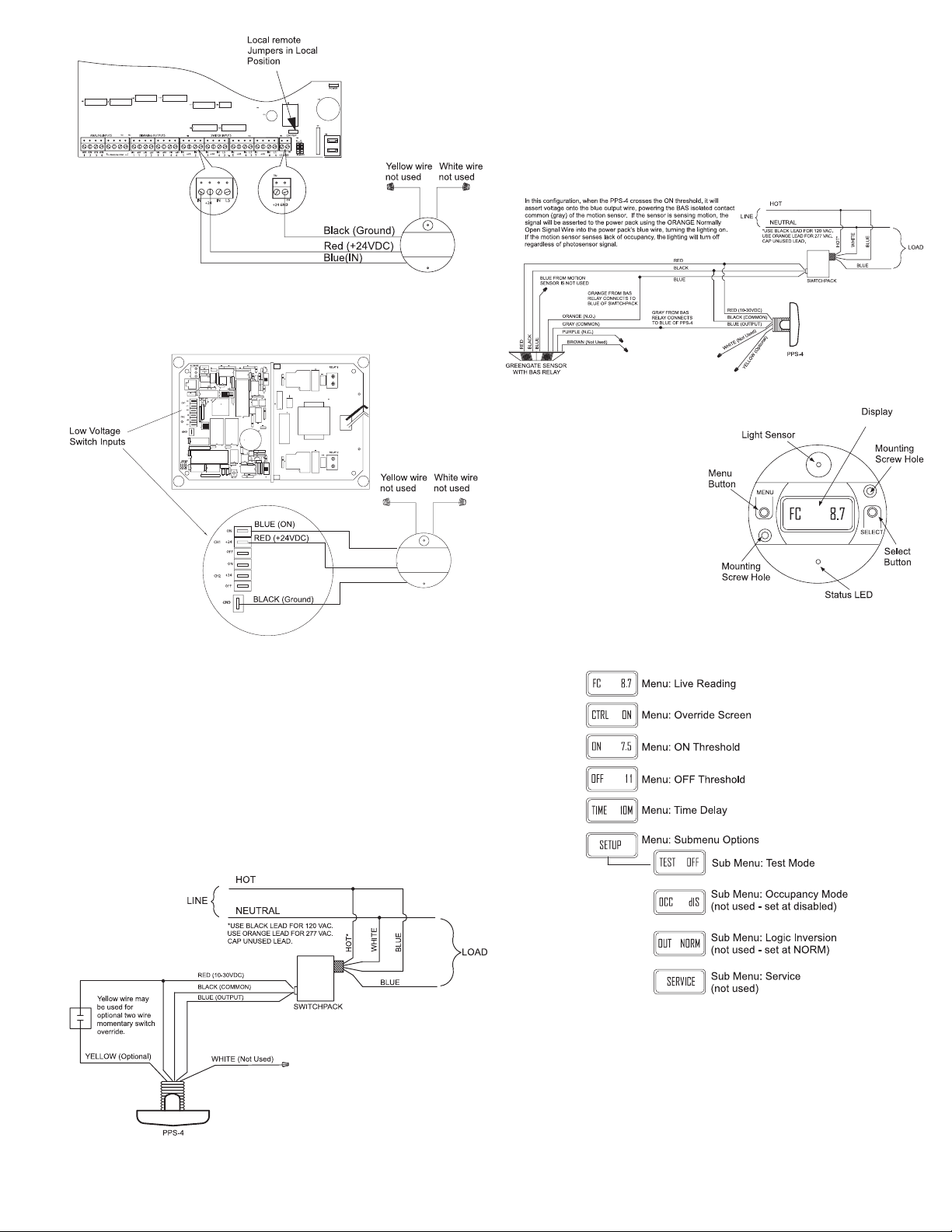
1. PopthecoveroffofthephotosensortoexposetheMenu
and Select buttons and display.
2. If the display is not illuminated, press the menu button.
The display will illuminate.
3. PressthemenubuttonuntiltheCTRLscreenisdisplayed.
4. Press the Select button to toggle the override between ON
and OFF. The display will update with the overridden status.
Verify that the lighting responds.
5. The override will remain active until the menu button is used
to cycle back through the menu options or will time out
automatically in 10 minutes.
Step 2: Setting the ON Threshold
It is best to set the PPS-4 switching thresholds when the space
is at the light level that the lights should turn ON. The default
setting is 7.5FC.
1. Make certain that the lighting is at the level in the space
where you want the lighting to turn on.
2. PressthemenubuttonuntilthedisplayisattheCTRL
menu.
3. Press the Select button until the display reads OFF and
the lights are OFF.
4. Press and hold the select button for 2 seconds until MEM
appears at the top of the sensor’s display.
5. Press the Menu button until the FC Reading Menu is
displayed. Make certain when reading this display that
you are not blocking the light source from reaching the
sensor. Make note of the current light level. This value
will be the desired FC target value for the ON threshold.
6. Press the menu button until the ON Threshold Menu is
displayed (ON XX).
7. Press the Select button until the closest FC value to the
noted reading is displayed.
8. When the desired FC threshold is displayed, press and
hold down the select button for about 2 seconds until
MEM appears at the top of the sensor’s display.
Step 3: Setting the OFF Threshold
The PPS-4 will calculate a 25%, 50%, 75% and 100% deadband
value for the OFF based on the ON threshold being used. The
default setting is 50% deadband. It is important to have adequate
separation between the ON and OFF thresholds to prevent cycling
due to thresholds being crossed when lighting is switched on and
off. To prevent this from occurring:
1. Set up the ON threshold.
2. PressthemenubuttonuntilthedisplayisattheCTRL
menu.
3. PresstheSelectbuttonuntilthedisplayreadsCTRLON
and the lights are ON.
4. Press and hold the select button for 2 seconds until MEM
appears at the top of the sensor’s display.
5. Press the Menu button until the FC Reading Menu is
displayed. Make certain when reading this display that
you are not blocking the light source from reaching the
sensor. Make note of the current light level.
6. PressthemenubuttonuntilthedisplayisattheCTRL
menu.
7. PresstheSelectbuttonuntilthedisplayreadsCTRLOFF
and the lights are OFF.
8. Press and hold the select button for 2 seconds until MEM
appears at the top of the sensor’s display.
9. Press the Menu button until the FC Reading Menu is
displayed. Make certain when reading this display that
you are not blocking the light source from reaching the
sensor. Make note of the current light level.
10.Take the initial reading with the lights on and subtract the
gure from the reading with the lights off. This is the
minimum deadband in FC that needs to be maintained
to prevent the lights from cycling.
11. Press the Menu button until the ON Threshold Menu is
displayed (ON XX).
12.Press the Select button to cycle through the available
OFF thresholds and select the appropriate setting.
13.Press and hold down the Select button for approx.
2 seconds until MEM appears at the top of the sensor’s
display window.
ON Value OFF Deadband Value
FC 25% 50% 75% 100%
1.0 1.2 1.5 1.7 2.0
1.2 1.5 1.8 2.1 2.4
1.5 1.8 2.2 2.5 3.0
1.8 2.2 2.7 3.1 3.6
2.2 2.7 3.3 3.8 4.4
2.7 3.3 4.0 4.6 5.4
3.3 4.1 4.9 5.7 6.6
4.0 5.0 6.0 7.0 8.0
5.0 6.2 7.5 8.7 10
6.0 7.5 9.0 11 12
7.5 9.3 11 13 15
9.0 11 14 16 18
11 14 17 19 22
13 16 20 23 26
16 20 24 28 32
20 25 30 35 40
25 31 38 44 50
30 38 45 53 60
35 44 53 61 70
45 56 68 79 90
60 75 90 105 120
90 113 135 158 180
125 156 188 219 250
180 225 270 315 360
250 313 375 438 500
325 406 488 569 650
400 500 600 700 800
475 594 713 NA NA
550 688 825 NA NA
625 781 938 NA NA
700 875 1050 NA NA
775 969 1163 NA NA
850 1063 1275 NA NA
Page 4

All products manufactured by Cooper Controls and identified with the Greengate brand are warranted to be free from defects in material and workmanship and
shall conform to and perform in accordance with Seller’s written specifications for a period of :
Five (5) years from date of shipment for all occupancy sensors.•
Three (3) years from date of factory invoice for our hardware and software on Lighting Control Panels.•
We warranty all our standard relays for a period of 10 years from date of factory invoice. We guarantee the performance of our system to specifications of your•
money back.
This warranty will be limited to the repair or replacement, at Seller’s discretion, of any such goods found to be defective, upon their authorized return to Seller. This
limited warranty does not apply if the goods have been damaged by accident, abuse, misuse, modification or misapplication, by damage during shipment or by
improper service. There are no warranties, which extend beyond the hereinabove-limited warranty, INCLUDING, BUT NOT LIMITED TO, THE IMPLIED WARRANTY
OF MERCHANTABILITY AND THE IMPLIED WARRANTY OF FITNESS.
No employee, agent, dealer, or other person is authorized to give any warranties on behalf of the Seller or to assume for the Seller any other liability in connection
with any of its goods except in writing and signed by the Seller.
The Seller makes no representation that the goods comply with any present or future federal, state or local regulation or ordinance. Compliance is the Buyer’s re-
sponsibility. The use of the Seller’s goods should be in accordance with the provision of the National Electrical Code, UL and/or other industry or military standards
that are pertinent to the particular end use. Installation or use not in accordance with these codes and standards could be hazardous.
P/N 05-014682-00
Step 3 Setting the Time Delay
The time delay setting determines how long the light level must
be above the OFF threshold before the lighting turns OFF. The
default setting is 10 minutes. To change this setting:
1. Press the menu button until the display shows the Time Delay
Menu (TIME #M). This is the current time delay setting.
2. Press the Select button until the desired choice is shown.
Choices include 3 minutes, 10 minutes, 20 minutes and
30 minutes.
3. When the desired number of minutes is displayed, press
and hold down the select button for about 2 seconds until
MEM appears at the top of the sensor’s display.
Additional PPS-4 Information
Testing the Sensor
It is possible to place the sensor in test mode. In this mode, the
sensor will immediately switch lighting on or off upon the cross
of the on or off thresholds. If a sensor is left in test mode, it will
automatically revert to normal operation after 30 minutes.
1. Press the menu button until the display reads SETUP.
2. Press the select button once. The display will read TEST.
3. Press the select button again. The display will read TEST
ONandthesensorLEDwillash.Thesensorisnowin
test mode.
4. Once test is complete, process steps 1-3 again to turn off
test mode.
It is also possible to test the sensor for functionality by overriding the
sensoronandoff.RefertotheStep1:VerifyControl–Overriding
the Sensor section for details on overriding the sensor.
Resetting the Sensor
It is possible to reset the sensor to factory defaults. Press and
hold both the Menu and the Setup buttons at the same time. The
display will default to the main screen and factory defaults will be
restored.
Additional functions of the photosensor are not used in the Green-
gate application.
LED Functions
LED Status
Description
OFF The lights are commanded
ON by the PPS-4
ON–solidGreen The lights are commanded
OFF by the PPS-4
Green–ashingrapidly
(once per second)
The PPS-4 is in test mode
Green–ashing
slowly (once every
four seconds)
The PPS-4 is being over-
riddeneitherbytheCTRL
override menu or by an
externaltwowiremomen-
tary wall switch.
Cooper Controls
203 Cooper Circle, Peachtree, GA 30269
800-553-3879
www.coopercontrol.com
Table of contents
Other Greengate Accessories manuals
Popular Accessories manuals by other brands

Town & Country Fireplaces
Town & Country Fireplaces TC30 Black Diamond instructions

Kodak
Kodak WSP801 Quick installation guide

Saje
Saje NATURAL WELLNESS aroma Bright manual

bsg
bsg PL192-112-072 instruction manual

Telco Sensors
Telco Sensors SM 3000/CAT2 Series user manual

CharlesWater
CharlesWater 99026 Installation, operation and maintenance

Johnson Controls
Johnson Controls NS Series installation instructions

Vinotemp
Vinotemp WINE-MATE WM-2520SSH Operation Care Installation Manual

JK Audio
JK Audio that-2 user guide

Fisher-Price
Fisher-Price DTM21 instruction sheet

AIBASE
AIBASE HA-ZW-5SABC quick start guide

Vortice
Vortice VORTPHON 1200 Instruction booklet