XG-Round Retrofit VAV Terminals Rev 2 4
Field Electrical Wiring
5All field wiring must comply with local building codes and
NEC. (ANSI/NFPA 70-2002)
5When Applicable, electrical control and piping diagrams are
attached to exterior of XG-Round Retrofit Air Terminal.
5Use copper only conductors.
5XG-Round Retrofit Air Terminal must be properly grounded
per NEC 424-14 and 250.
5Always check product label for voltage and current data to
determine the proper wire size and over current protection.
5The control cabinet contains live electrical parts.
5Contacting these parts with power applied may cause seri-
ous injury or even death.
5The control panel cover must be closed or in place before
applying electric power to the XG-Round Retrofit Air Termi-
nal.
5These recommendations are not meant to precluded NEC
requirements or applicable local building codes and are the
sole responsibility of the installing contractor.
Important
If equipped with pneumatic controls, the orientation of the XG-
Round Retrofit Air Terminal unit is critical. The pneumatic controls
must be mounted right side up. The XG-Round Retrofit Air Terminal
must be level within + or – 10 degrees of horizontal, both parallel
to the air flow and at right angle of air flow. The control side of the
XG-Round Retrofit Air Terminal is labeled with an arrow indicat-
ing up. Unless otherwise noted, most electric, analog electronic
and digital are not position sensitive and may be installed in any
orientation.
Controls
For information on controls provided by other manufactures and
installed on the XG-Round Retrofit Air Terminals, contact the local
branch or dealer. Installing the Air Terminal in a different location
than noted on the XG-Round Retrofit Air Terminal label and build-
ing plans, may result in excessive start up labor and is the sole
responsibility of the contractor.
Important
XG-Round Retrofit Air Terminals with digital controls, if factory pro-
grammed, incorporate specific communication addresses.
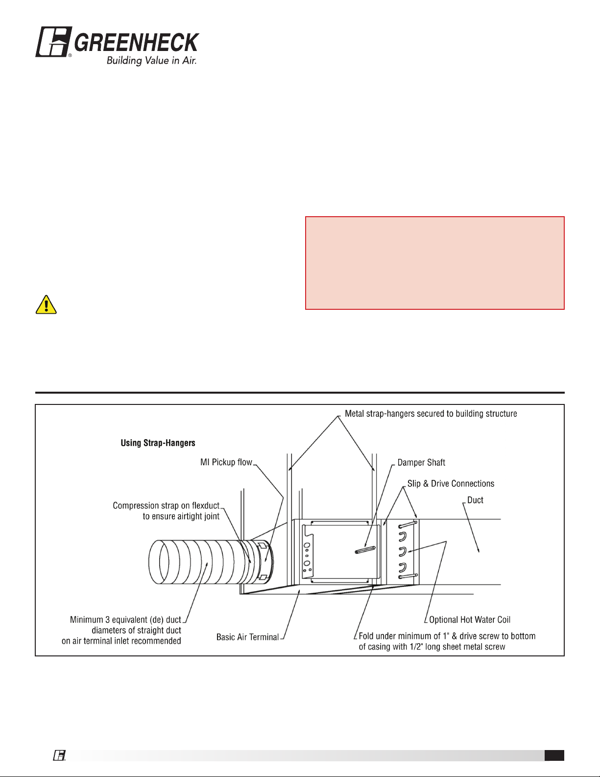
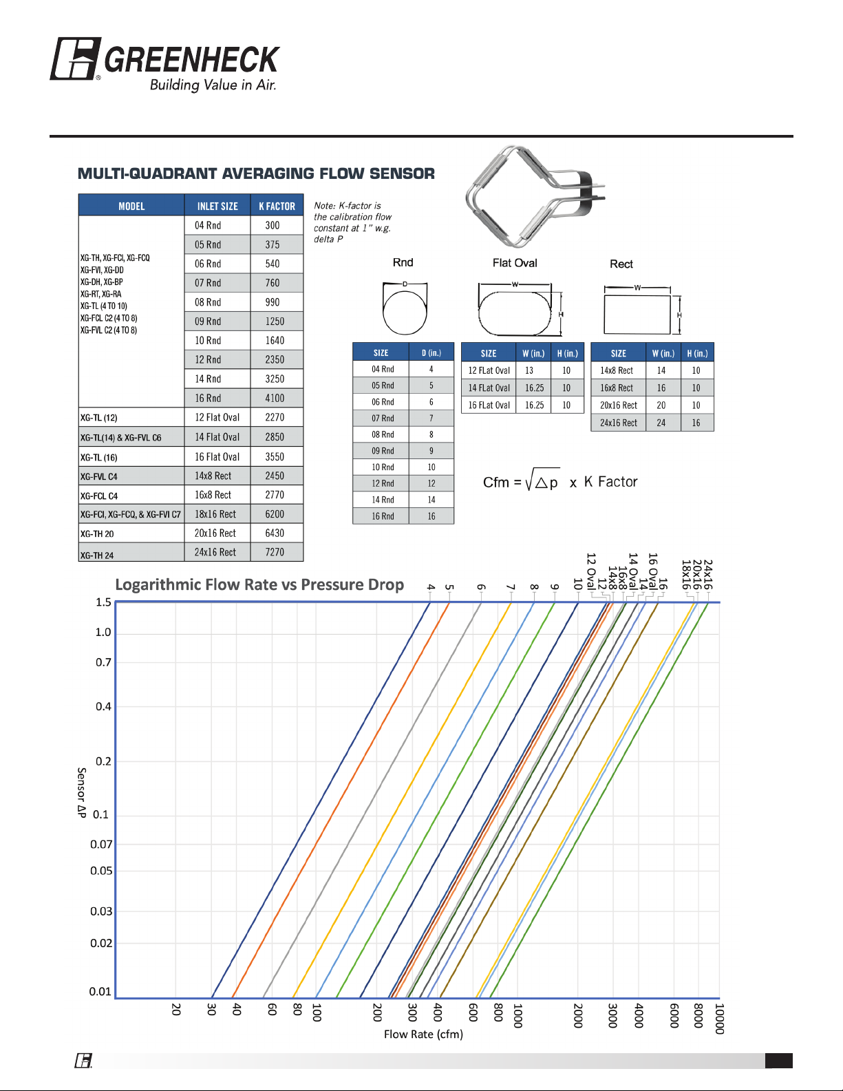
Inlet Flow Sensor
XG-Round Retrofit Air Terminals are shipped with factory
installed (where applicable) pressure differential inlet flow sensors
in the primary inlet. See figure 3 for calibration curve and K
factors.
Labeling
XG-Round Retrofit Air Terminals are shipped from the factory with
multiple information labels.
Control Sequence Label: Affixed to the exterior of the
XG-Round Retrofit Air Terminal casing. Displays piping/wir-
ing diagram, control sequence number and any optional
components.
Terminal I.D. Label: Affixed to the exterior of XG-Round
Retrofit Air Terminal. Shows tagging, representative name,
sales order number, applicable certifications, model number,
Made in USA, any applicable electrical data and UL compli-
ance markings.
AHRI Certification Label: Identifies applicable industry
test standard and certifies Air Terminal is in compliance.
Orientation Label: Identifies the proper air flow direction
and top of Round Retrofit Air Terminal.
Troubleshooting
Investigating Noise Complaints
5Noise from a Round Retrofit Air Terminal can be due to a
variety of conditions and can be difficult to eliminate.
5The first step is to isolate the type, source and direction.
5Generally noise heard at the air outlet is considered a dis-
charge type.
5Noise heard through the ceiling is considered radiated noise.
5For detailed information concerning noise transmission in
buildings, refer to AHRI Standard 885-2008,
“Procedure for estimating occupied space sound levels in
the application of Air Terminals and air outlets”.
Discharge Noise
5This is usually caused by high static or little to no internal duct
lining downstream of the Round Retrofit Air Terminal.
5It can sometimes be caused by air outlet itself.
5Air outlet generated sounds can be reduced by reducing flow
or increasing an outlet size.
5Reducing static pressure, flow or adding additional down-
stream attenuation materials will reduce discharge sounds
from the Air Terminal.
Radiated Noise
5Radiated noise is most commonly associated with Fan Pow-
ered Terminals.