9
1. Installation of venting must conform with local
building codes. In the absence of local codes,
installation must conform with the National Fuel
Gas Code, ANSI Z223.1 or in Canada, CAN/CGA-
B149 installations codes.
2. The classification for vertical and horizontal venting
of all units is category III. The ANSI requirements
for vents classified as category III is that they must
be gas tight. Seal the joints with a metallic tape or
silastic suitable for temperatures up to 350 degrees
F. the venting system shall be installed in
accordance with these instructions.
3. All pipe is field supplied by others. For the vent
pipe, use pipe approved for a category III appliance
or single wall, 26 gauge or heavier galvanized vent
pipe. For the combustion air pipe on separated
combustion units, sealed single-wall galvanized air
pipe is recommended. Refer to the National Fuel
Gas Code for additional piping guidelines.
4. Select the vent and combustion air pipe size from
the tables (1) and (2) shown on the following pages.
Select the size of the vent and combustion air pipe
that fits the flue outlet and combustion air intake.
Use only the pipe size specified.
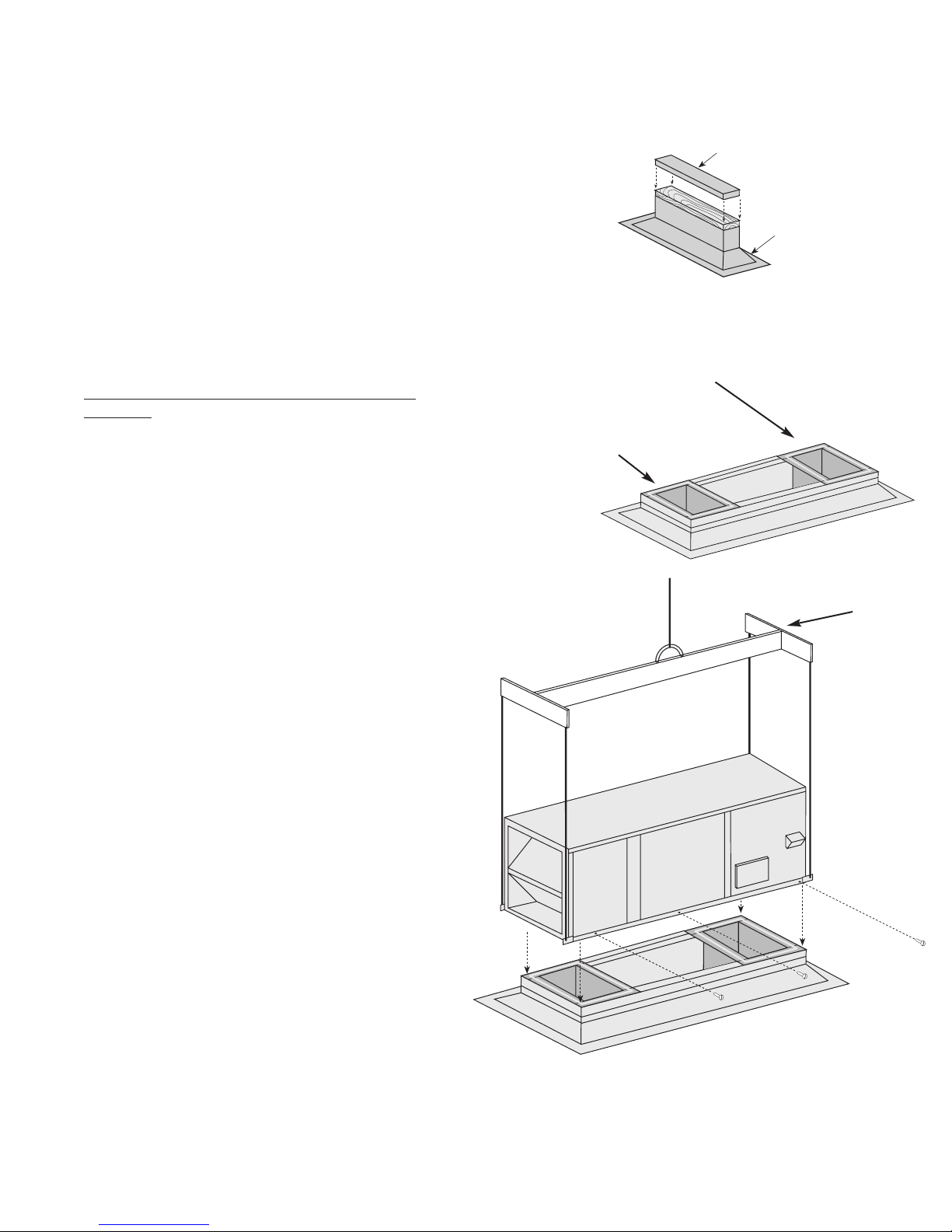
5. Install the vent and combustion air pipes with
minimum downward slopes (from the unit) of 1/4
inch per foot, suspend securely from overhead
structures at points no greater than 3 feet apart.
Fasten individual pipe lengths together with at least
three corrosion resistant sheet metal screws.
6. For the vent pipe, a minimum of 12 inches of
straight pipe is recommended at the flue outlet
before any elbows.
7. Avoid venting through unheated spaces if possible.
To minimize condensation, insulate any vent runs
greater than 5 feet that must pass through an
unheated space.
8. For the combustion air pipes, long runs in cold
climates may require insulation to prevent the
buildup of condensation on the outside of the pipes
where the pipe passes through heated spaces.
9. Vertical combustion air pipes should be fitted with a
tee with a drip leg and clean out cap to prevent any
moisture in the combustion air pipe from entering
the unit. The drip leg should be cleaned out
periodically during the heating season.
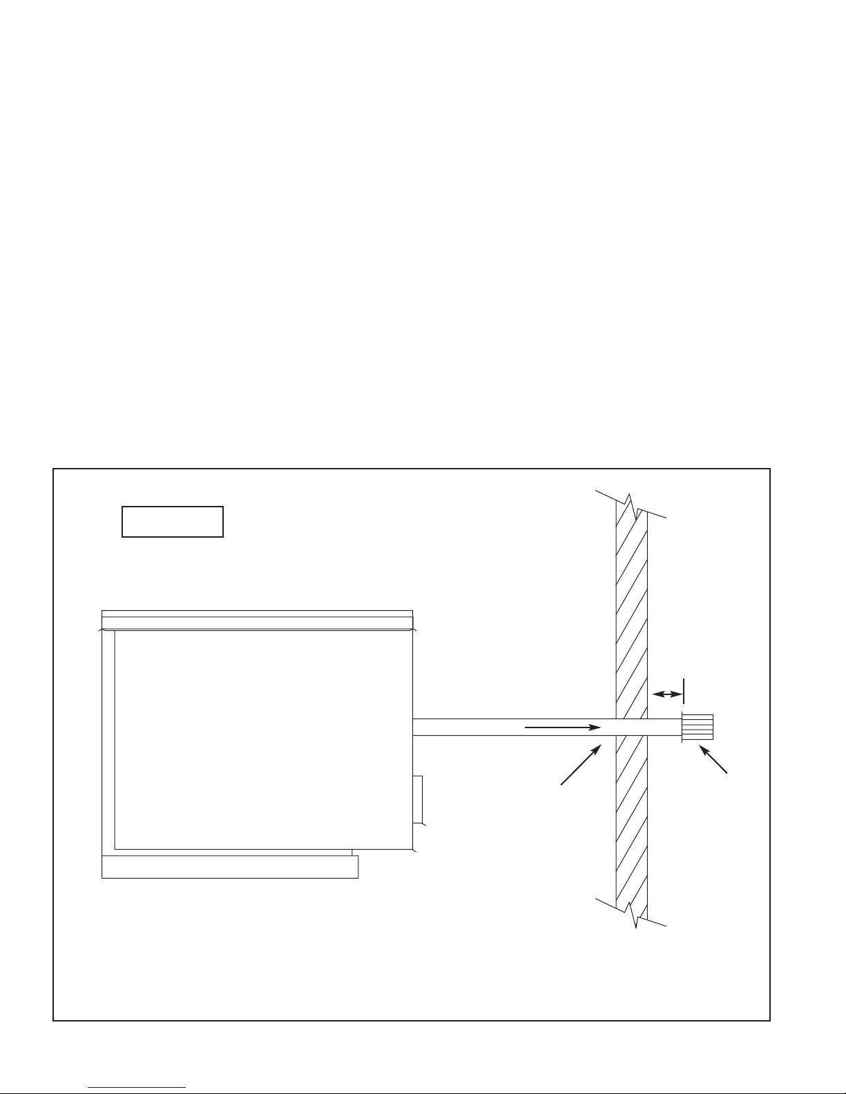
10.For separated combustion systems, the wall
thickness for the purpose of venting is 1 inch
minimum, 48 inches maximum.
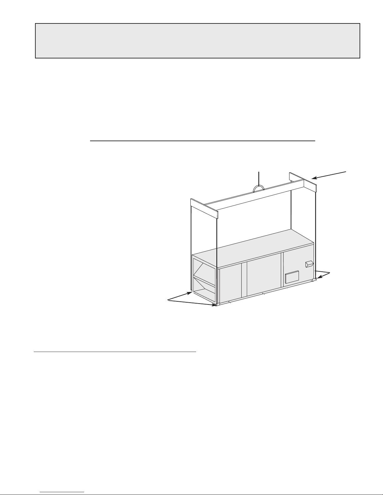
•Standard Indoor Venting (uses building air for combustion)
•Separated Combustion Concentric Venting (uses outside air for combustion, one exterior roof or wall
penetration)
•Separated Combustion 2-Pipe Venting (uses outside air for combustion, two exterior roof or wall penetrations)
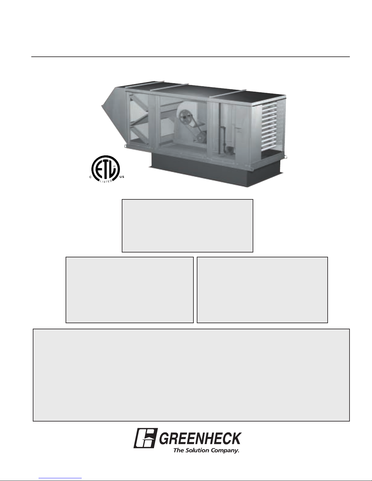
For each method, the units can be vented horizontally through an exterior wall or vertically through the roof.
Refer to the following pages for specific venting instructions. Construct the vent system for the selected
method, as shown in these instructions. When looking in the direction of airflow, the venting is on the right side
of the unit.
Furnace Vent Standard Separated Combustion Separated
Size Lengths Indoor Concentric Combustion 2-pipe
100 - 300 min 5 ft. 5 ft. 5 ft.
max 70 ft. 70 ft. 70 ft.
350 - 400 min 5 ft. 5 ft. 5 ft.
max 70 ft. 70 ft. 50 ft.
VENT LENGTHS FOR EXHAUST AND COMBUSTION AIR
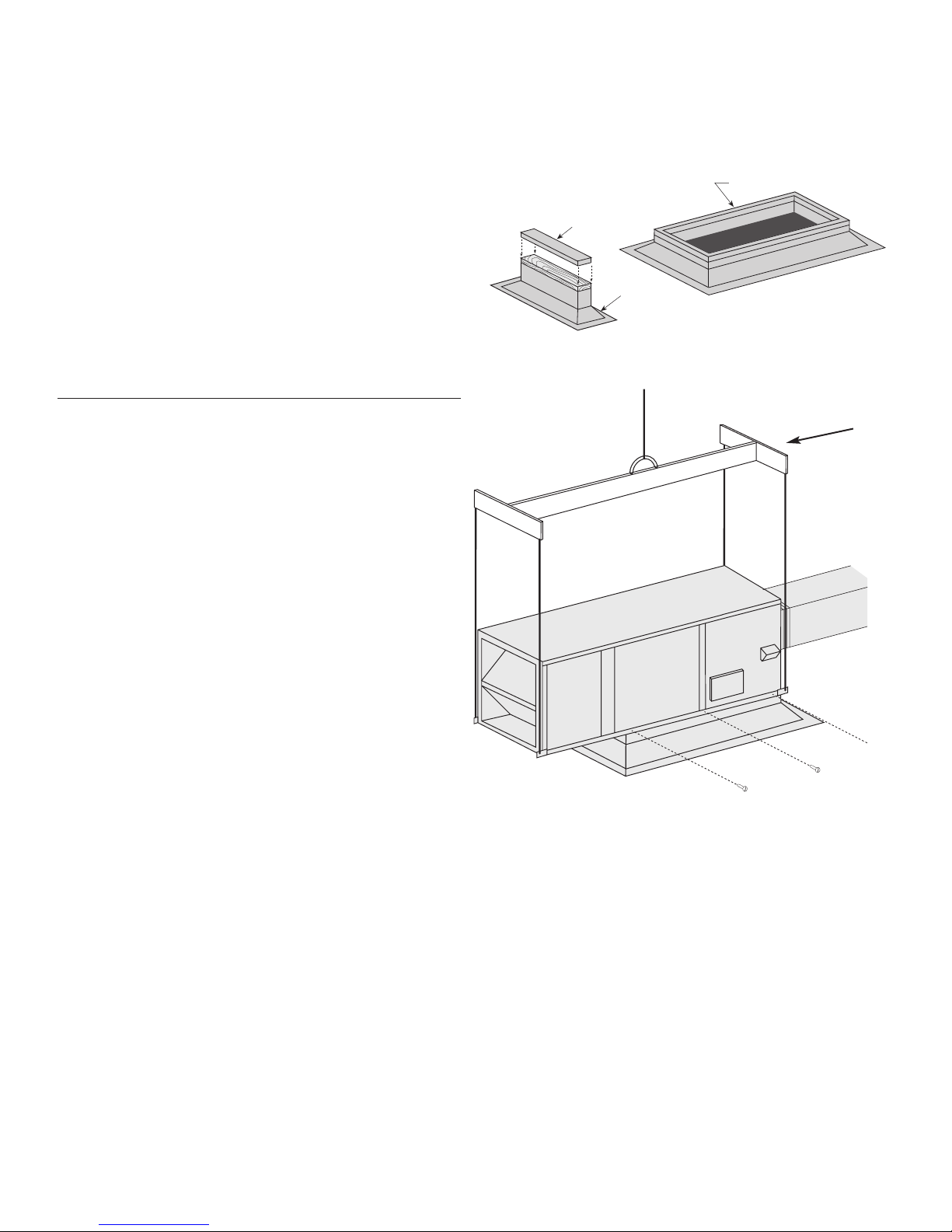
Venting Instructions:
Indoor Units
Venting Methods for Indoor Units