Greenlee PG1 User manual

INSTRUCTION MANUAL
PG1 Tester
Read and understand all of the instructions and
safety information in this manual before operating
of servicing this tool.
52026635 © 2007 Greenlee Textron Inc. 5/07

PG1 Tester
Greenlee / A Textron Company 4455 Boeing Dr. • Rockford, IL 61109-2988 USA • 815-397-7070
2
Description
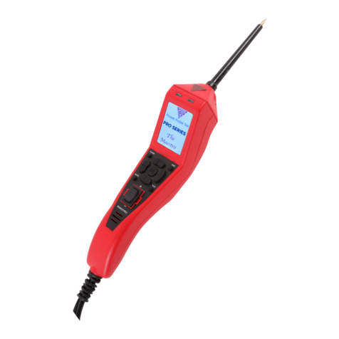
The Greenlee PG1 Tester is a hand-held testing device
intended for reading-out, replacing, and programming
the programmable controller memory of Greenlee’s
electro-hydraulic battery-powered tools.
The PG1 consists of a shock-proof aluminum case with
a four-line display and ve operation keys. The pro-
gramming is menu-driven, and for the most part it is
self-explanatory. An optional 115 V/60 Hz power supply
(50065734) is available for the PG1.
Safety
Safety is essential in the use and maintenance of
Greenlee tools and equipment. This manual and any
markings on the tool provide information for avoiding
hazards and unsafe practices related to the use of this
tool. Observe all of the safety information provided.
Purpose of this Manual
This manual is intended to familiarize all personnel with
the safe operation and maintenance procedures for the
following Greenlee tool:
PG1 Tester
Keep this manual available to all personnel.
Replacement manuals are available upon request at no
charge at www.greenlee.com
All specications are nominal and may change as design
improvements occur. Greenlee Textron Inc. shall not be liable for
damages resulting from misapplication or misuse of its products.
KEEP THIS MANUAL
Table of Contents
Description .................................................................... 2
Safety ............................................................................ 2
Purpose of this Manual ................................................. 2
Important Safety Information .....................................3–4
Identication.................................................................. 5
Specications................................................................ 5
Setup ............................................................................. 6
Operation....................................................................... 6
Troubleshooting............................................................. 7

PG1 Tester
Greenlee / A Textron Company 4455 Boeing Dr. • Rockford, IL 61109-2988 USA • 815-397-7070
3
IMPORTANT SAFETY INFORMATION
SAFETY
ALERT
SYMBOL
This symbol is used to call your attention to hazards
or unsafe practices which could result in an injury or
property damage. The signal word, dened below,
indicates the severity of the hazard. The message
after the signal word provides information for
preventing or avoiding the hazard.
Immediate hazards which, if not avoided, WILL result
in severe injury or death.
Hazards which, if not avoided, COULD result in
severe injury or death.
Hazards or unsafe practices which, if not avoided,
MAY result in injury or property damage.
Read and understand all of the
instructions and safety information
in this manual before operating or
servicing this tool.
Failure to observe this warning could
result in severe injury or death.
Electric shock hazard:
Contact with live circuits could result
in severe injury or death.
Wear eye protection when operating
this tool.
Failure to wear eye protection could
result in serious eye injury from ying
debris.
Electric shock and re hazard:
Do not expose this unit to rain or moisture.
Do not use the unit if it is wet or damaged.
Inspect accessories before use. They must be
clean and dry, and the insulation must be in good
condition.
Use this unit for the manufacturer’s intended pur-
pose only, as described in this manual. Any other
use can impair the protection provided by the unit.
Failure to observe these warnings could result in
severe injury or death.
•
•
•
•

PG1 Tester
Greenlee / A Textron Company 4455 Boeing Dr. • Rockford, IL 61109-2988 USA • 815-397-7070
4
Do not operate with the case open.
Before opening the case, remove the accessories
and shut off the unit.
Failure to observe these warnings could result in
severe injury or death.
•
•
Do not dispose of the battery in a re. The battery will
vent fumes and it could explode.
Failure to observe this warning could result in severe
injury from harmful fumes or burns from ying debris.
Do not attempt to repair this unit. It contains no
user-serviceable parts.
Do not expose the unit to extremes in temperature
or high humidity.
Failure to observe these precautions may result in
injury and may damage the unit.
•
•
IMPORTANT SAFETY INFORMATION
Do not use another manufacturer’s charger.
Other manufacturers’ chargers may overcharge
and damage the battery.
Using this unit near equipment that generates
electromagnetic interference can result in unstable or
inaccurate readings.

PG1 Tester
Greenlee / A Textron Company 4455 Boeing Dr. • Rockford, IL 61109-2988 USA • 815-397-7070
5
Identification
1. Display
2. LED
3. Diode holder
4. Cord
5. Up arrow key
6. Check mark key
7. Down arrow key
8. ON key
9. OFF key
10. Battery cover
11. AC adapter plug
1
11
7
8
9
5
6
2
3
4
10
Specifications
Weight (including diode holder) ..............................................................0.8 kg (1.8 lb)
Length of transmission cable ...........................................approx. 800 mm (31-1/2 in)
System protection ...............................................................................................IP 40
Display......................................................4 x 16 DOT-memory matrix character LCD
Angular eld LCD ..................................................................................-10° up to 40°
External power supply......................................................12 V, 24 V, minimum 50 mA
Recommended powerpack.................................................. FW 1288 12 V or 24 V
Type of battery............................................................................. 9 V E-block 6 LR 61
Temperature range ......................................................0° C to 55° C (32 °F to 131 °F)
Dimensions (approximate)
Length .........................................................................................235 mm (9-1/4 in)
Width (min.) ...................................................................................80 mm (3-1/8 in)
Width (max.) ................................................................................105 mm (4-1/8 in)
Depth.............................................................................................32 mm (1-1/4 in)

PG1 Tester
Greenlee / A Textron Company 4455 Boeing Dr. • Rockford, IL 61109-2988 USA • 815-397-7070
6
Setup
The following functions can be accessed before placing
the diode holder on the tool to be tested:
Choose language: Press the ON key. When the serial
number of the PG1 is displayed, press and hold ↓
until the language choices appear on the display. Use
↑and ↓to select “German” or “English”. Press √ to
conrm the selection.
Adjust contrast: Press the ON key. When the serial
number of the PG1 is displayed, press and hold the
↑key until “LCD Contrast” appears on the display.
The standard (default) setting comes up automatically
but can be changed by pressing ↑and ↓. Press √ to
conrm the setting.
Display charging stage: Press the ON key. When the
serial number of the PG1 is displayed, press and hold
the √ key until the charging status is displayed.
If the charging condition of the battery is less than
10%, replace the battery. To replace the battery,
remove the battery cover, open the battery shelf, and
replace with a new 9 V battery.
Operation
1. Press the ON key.
2. Place the PG1 LED (located on the diode holder)
onto the LED of the tool to be tested.
3. Briey touch the power trigger of the tool.
4. The PG1 will display the serial number of the tool
and, if available, the date code, the type designa-
tion, and special features of the tool.
Press √ to move to the next screen. In both of the
bottom lines of the display, the menu point “reset”
and “main menu” are indicated. The menu points
are triggered with the ↑and ↓keys, and selected
with the √ key. “Reset” sets the current delta-values
(values since the last maintenance) to zero after
maintenance has been performed. If you choose
“main menu”, you will go to the next screen.
5. Maintenance:
From the main menu you can select an additional
menu, which consists of the following points:
Reset: Sets the current delta-values to zero
(= a.m. menu point).
Indicating values: limit stops; by reset the delta-
value is set to zero, the “total” value remains as
it was and shows the total number of limit stops
(cycles) carried out with the tool. Use ↓to move
to the next page. Disconnection “on” means that
the circuit cuts off the motor after a completed
cycle. The bonus states how many crimps can be
made exceeding the determined number before
the start of the maintenance indication (ashing)
before the tool is going to be out of action (shuts
•
•
•
•
•
down for service). The menu point “limit stops“
shows the pre-adjusted number of limit stops until
the maintenance indication of the tool indicates
the next maintenance. On the next screen the
energy consumption is indicated. The delta-value
is set to zero again at reset, and the total value is
xed.
On page 4/5 the number of measurements is
indicated. At reset the delta-value is set to zero
again, and the total value remains xed. On page
5/5 the version of the circuit board and what it
was programmed to is displayed. Use the √ key to
return to the main menu.
Changing values: If you choose this menu point
with ι, you can set new maximum limit stops for
the beginning of the maintenance indication of
the tool. Use ↑and ↓to increase or decrease the
value. Press √ to move to the next screen, where
you are required to conrm the value you chose.
In the second menu point you can change the
value once more or readjust again the original
value in the third menu point. In the next screen
you can adjust the bonus-limit stops. A range of
0-255 is preset. 0 means that the bonus is set
on “innite”. In fact a maintenance which is due
is then indicated now as before but there is no
functional blocking. After this you are requested
to conrm the chosen value with the √ key. In the
next screen you select whether or not the tool
should turn the motor off after a completed cycle.
For this value, cutters are set at 0, while crimping
tools are set at 1. Conrm input with the √ key.
Afterwards the value can be changed once more
and the original value can be adjusted again. If
this value is conrmed with OK (!), you will go
back to the main menu.
6. Serial number (= entry window)
7. Control: The indicated values are for the manufac-
turer’s control.
8. Options: Refer to the “Setup” section of this
manual.
9. The PG1 automatically shuts off after 5 minutes of
inactivity.
•

PG1 Tester
Greenlee / A Textron Company 4455 Boeing Dr. • Rockford, IL 61109-2988 USA • 815-397-7070
7
Troubleshooting
Problem Probable Cause Possible Remedy
No indication Battery discharged Replace batteries.
Contrast too low Adjust contrast; refer to the “Setup” section.
No values PG1 LED dirty Clean LED with a dry cloth.
Defective cable Exchange cable or return tool to an authorized Greenlee
service center.
Defective board Return tool to an authorized Greenlee service center.
Dead battery Charge or replace battery.
Maintenance
Do not attempt to repair this unit. It contains no user-
serviceable parts.
Failure to observe this precaution may result in injury
and may damage the unit.
Cleaning
Periodically wipe the case with a damp cloth and mild
detergent; do not use abrasives or solvents.

USA 800-435-0786 Fax: 800-451-2632
815-397-7070 Fax: 815-397-1865
Canada 800-435-0786 Fax: 800-524-2853
International +1-815-397-7070 Fax: +1-815-397-9247
4455 Boeing Drive • Rockford, IL 61109-2988 • USA • 815-397-7070
An ISO 9001 Company • Greenlee Textron Inc. is a subsidiary of Textron Inc.
www.greenlee.com
Table of contents
Other Greenlee Circuit Tester manuals

Greenlee
Greenlee GT-65e User manual

Greenlee
Greenlee GT-65 User manual

Greenlee
Greenlee PairMapper User manual

Greenlee
Greenlee GT-10 Manual

Greenlee
Greenlee 5708 User manual

Greenlee
Greenlee 1110 User manual

Greenlee
Greenlee GT-10 User manual

Greenlee
Greenlee LT-100 User manual

Greenlee
Greenlee GT-10GFI User manual

Greenlee
Greenlee GT-55e User manual