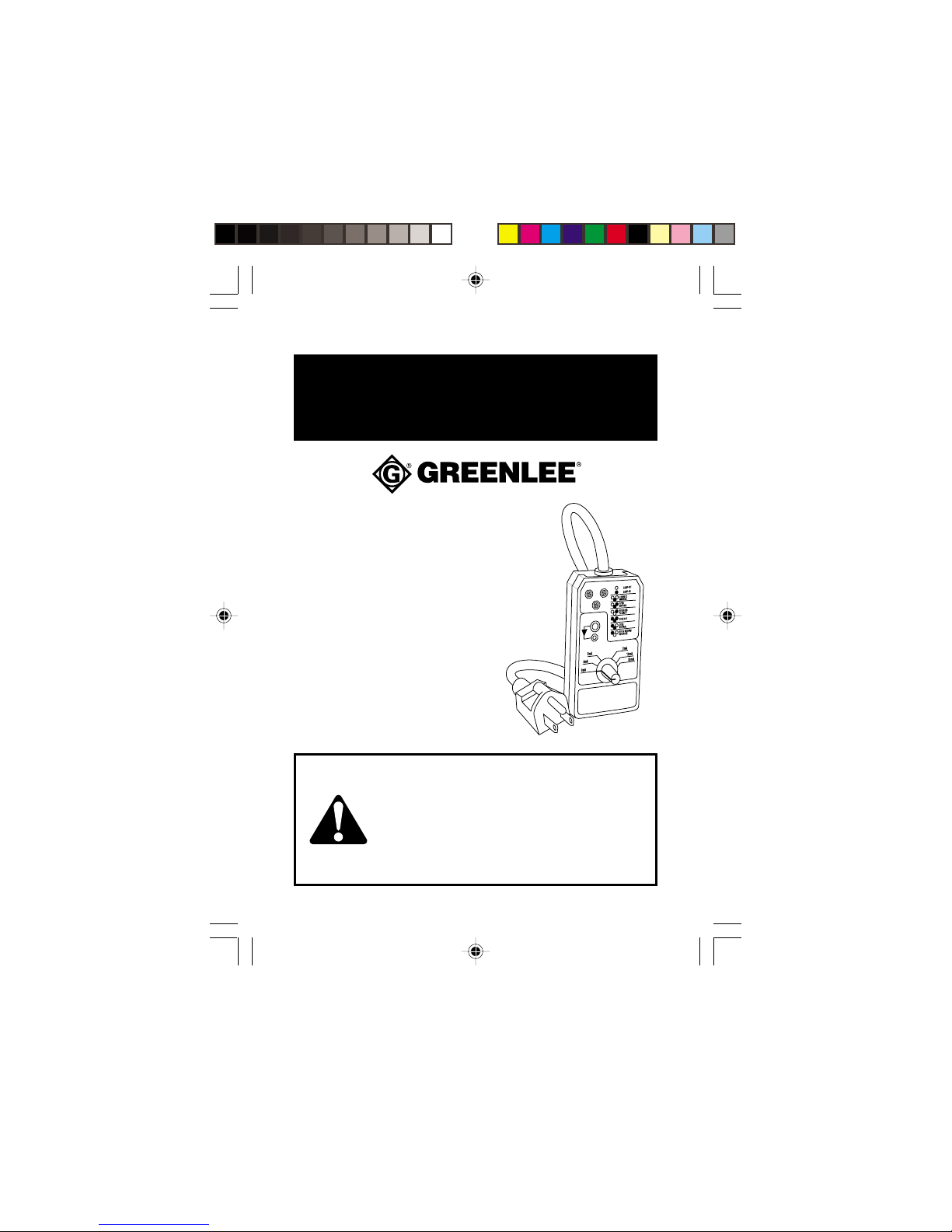
Greenlee 5708 User manual

999 3261.0 © 2000 Greenlee Textron IM 1405 1/00
5708 • 5708-I
GFCI AND CIRCUIT
TESTERS
VERIFICADORES
DE CIRCUITO Y GFCI
VERIFICATEUR
DE CIRCUITS ET
DE DISJONCTEURS
DIFFERENTIELS
INSTRUCTION MANUAL
MANUAL DE INSTRUCCIONES
MANUEL D’INSTRUCTIONS
Read and understand all of the instructions and safety
information in this manual before operating or servicing
this tool.
Lea y entienda todas las instrucciones y la información
sobre seguridad que aparecen en este manual, antes de
manejar estas herramientas o darles mantenimiento.
Lire attentivement et bien comprendre toutes les
instructions et les informations sur la sécurité de ce manuel
avant d‘utiliser ou de procéder à l‘entretien de cet outil.

2
Description
The Greenlee 5708 and 5708-I GFCI and Circuit Testers are intended to
verify the operation of a three-wire 120 volt ground fault circuit
interrupter that has a standard (NEMA 5-15R) receptacle.
In addition to the GFCI testing capability, the 5708 and 5708-I also verify
that the wiring is correct. They do not perform comprehensive diagnostic
testing, but perform a simple check that detects most common wiring faults
on three-wire circuits. Be aware that these tools will not detect two hot
wires in a circuit, reversed grounded and grounding conductors, or multiple
wiring faults. Also, they cannot indicate the quality of a ground.
In this manual, the term “GFCI” refers to a ground fault interrupter or a
ground fault circuit interrupter.
Safety
Safety is essential in the use and maintenance of Greenlee tools and
equipment. This instruction manual and any markings on the tool
provide information for avoiding hazards and unsafe practices related to
the use of this tool. Observe all of the safety information provided.
Purpose
This instruction manual is intended to familiarize all personnel with the
safe operation and maintenance procedures for the Greenlee 5708 and
5708-I GFCI and Circuit Testers.
Keep this manual available to all personnel. Replacement manuals are
available upon request at no charge.
and are registered trademarks of
Greenlee Textron.
KEEP THIS MANUAL

5708 • 5708-I
3
Important Safety Information
This symbol is used to call your attention to hazards or unsafe
practices which could result in an injury or property damage.
The signal word, defined below, indicates the severity of the
hazard. The message after the signal word provides information
for preventing or avoiding the hazard.
SAFETY ALERT SYMBOL
Immediate hazards which, if not avoided, WILL result in severe
injury or death.
Hazards which, if not avoided, COULD result in severe injury or
death.
Hazards or unsafe practices which, if not avoided, MAY result in
injury or property damage.

4
Read and understand this material before
operating or servicing this equipment. Failure
to understand how to safely operate this tool
can result in an accident causing serious
injury or death.
Important Safety Information
Electric shock hazard:
• Contact with live circuits can result in
severe injury or death.
• The 5708 and 5708-I cannot properly test
two-wire circuits.
Electric shock and fire hazard:
• Do not expose this unit to rain or moisture.
• Use this unit for the manufacturer’s intended purpose only, as
described in this manual. Any other use can impair the protection
provided by the unit.
Failure to observe these warnings can result in severe injury or
death.

5708 • 5708-I
5
Important Safety Information
Electric shock hazard:
• Do not apply more than the rated voltage between any two input
terminals, or between any input terminal and earth ground.
• Do not contact the test lead tips or any uninsulated portion of the
accessory.
Failure to observe these warnings can result in severe injury or
death.
Electric shock hazard:
• Do not use the unit if it is wet or damaged.
• Inspect the test leads or accessory before use. The item(s) must
be clean and dry, and the insulation must be in good condition.
Failure to observe these warnings can result in severe injury or
death.

6
Important Safety Information
Using this unit near equipment that generates electromagnetic
interference can result in unstable or inaccurate readings.
• Do not attempt to repair this unit. It contains no user-serviceable
parts.
• Do not expose the unit to extremes in temperature or high
humidity. See Specifications.
Failure to observe these precautions can result in injury and can
damage the unit.

5708 • 5708-I
7
Identification
1. Circuit Test Lights
and Diagrams Used to determine correct or incorrect wiring.
2. Test LEDs Green LED indicates that the unit is connected
to a live circuit.
Red LED indicates that a test is in progress.
3. Selector Used to set the leakage current.
The 5708-I also shows the time duration
of the leakage current.
1
2
3

8
Introduction
The 5708 and 5708-I GFCI and Circuit Testers are used to verify the
wiring and to check the operation of three-wire 120 volt ground fault
circuit interrupters. The units connect a resistor between the hot lead
and ground to create a small amount of leakage current. The GFCI is
intended to trip when the leakage current is between 5 and 7 milliamps.
When the GFCI trips, the circuit is opened and all the LEDs will shut off.
If the GFCI does not trip within a specified time period, the GFCI is faulty
and must be replaced.
• The 5708 creates the leakage current for 200 milliseconds, then
shuts off for 4 seconds. This sequence is repeated continuously.
• The 5708-I creates the leakage current for the time duration indicated
on the front of the unit, then shuts off. Total cycle time is approxi-
mately 17 seconds, regardless of the selector setting. The sequence
is repeated continuously.

5708 • 5708-I
9
1. To help prevent false readings, unplug any appliances or equipment
on the circuit under test.
2. Set the selector to 0 mA and plug the unit into the GFCI’s receptacle
(NEMA 5-15R type only).
3. Compare the LEDs illuminated on the 5708 or 5708-I to the
diagram on the face of the unit.
Note: If the LEDs indicate anything other than “Correct Wiring”,
have the wiring corrected by a qualified electrician.
4. Press the GFCI’s built-in reset button, then press its test button.
5. After resetting the GFCI, move the selector to the next higher setting.
The red test LED will turn on to indicate that testing is in progress, and
will turn off when the test is finished or when the GFCI trips.
6. Wait for the red LED to turn on and off. Observe the yellow LEDs on
the unit to determine if the GFCI has tripped. If not, move the
selector to the next higher setting. Repeat this process until the
GFCI trips or until the highest setting is reached. The setting at
which the GFCI trips is the Leakage Current Trip Point. See the
Settings Table.
Electric shock hazard:
•Contact with live circuits can result in
severe injury or death.
•The 5708 and 5708-I cannot properly test
two-wire circuits.
Operation

10
7. Plug the unit into every receptacle on the circuit, including all
remotely connected receptacles on all branches that are in series
with the GFCI. Using the procedure detailed above, verify that every
receptacle is properly wired to and protected by the GFCI.
Operation (cont’d)
Settings Table
Leakage Current Trip Point GFCI Condition
Trips at 3 mA GFCI is oversensitive.
Trips at 5 mA GFCI is acceptable.
Trips at 6 mA (5708-I only) GFCI is acceptable.
Trips at 7 mA GFCI is acceptable.
Trips at 10 mA GFCI is faulty. REPLACE THE GFCI.
Trips at 30 mA (5708 only) GFCI is faulty. REPLACE THE GFCI.
Does not trip. GFCI is faulty, or it was wired incorrectly
when it was installed. Have a qualified
electrician verify that it was installed
and wired according to the GFCI
manufacturer’s instructions. If the GFCI
still does not trip, REPLACE THE GFCI.

5708 • 5708-I
11
Accuracy
Accuracy for Leakage Current: ±10% at nominal line voltage
Accuracy for Test Time:
5708: 200 ms minimum, 250 ms maximum
5708-I: ±1.5%
Test Table
Specifications
Storage/Operating Conditions: 57 °C (135 °F) maximum
Relative Humidity: 80% maximum
Altitude: 2000 m (6500') maximum
Indoor use only
Pollution Degree: 2
Cleaning
Periodically wipe the case with a damp cloth and mild detergent; do not
use abrasives or solvents.
Leakage Current Test Duration
5708 5708-I
3 mA 200 milliseconds 15 seconds
5 mA 200 milliseconds 5 seconds
6 mA —4 seconds
7 mA 200 milliseconds 3 seconds
10 mA 200 milliseconds 2 seconds
30 mA 200 milliseconds —

12
Descripción
Los verificadores de circuito y GFCI 5708 y 5708-I de Greenlee han sido
diseñados para comprobar el funcionamiento de un interruptor de
circuito de falla a tierra trifilar de 120 voltios que cuente con un
receptáculo estándar (NEMA 5-15R).
Además de la capacidad de verificación de GFCI, los modelos 5708 y
5708-I comprueban también que el cableado sea el correcto. Estos no
realizan pruebas de diagnóstico exhaustivas sino una verificación
sencilla que detecta las fallas de cableado más comunes en los circuitos
trifilares. Tenga muy presente que estas herramientas nodetectan dos
cables energizados en un mismo circuito, ni conexiones a tierra
invertidas ni conductores a tierra, ni fallas de cableado múltiples.
Tampoco indican la calidad de una conexión a tierra.
Para propósitos de este manual el término “GFCI” se refiere a un
interruptor de falla a tierra o un interruptor de circuito de falla a tierra.
Acerca de la seguridad
Es fundamental observar métodos seguros al utilizar y dar mantenimiento a
las herramientas y equipo Greenlee. Este manual de instrucciones y todas
las marcas que ostenta la herramienta le ofrecen la información necesaria
para evitar riesgos y hábitos poco seguros relacionados con su uso. Siga
toda la información sobre seguridad que se proporciona.
Propósito de este manual
Este manual de instrucciones tiene como propósito familiarizar a todo el
personal con los procedimientos de operación y mantenimiento seguros
para los Verificadores de Circuito y GFCI 5708 y 5708-I de Greenlee.
Manténgalo siempre al alcance de todo el personal. Puede obtener
copias adicionales de manera gratuita, previa solicitud.
y son marcas registradas de Greenlee
Textron.
CONSERVE ESTE MANUAL

5708 • 5708-I
13
Importante Información sobre Seguridad
Este símbolo se utiliza para indicar un riesgo o práctica poco
segura que podría ocasionar lesiones o daños materiales. Cada
uno de los siguientes términos denota la gravedad del riesgo. El
mensaje que sigue a dichos términos le indica cómo puede
evitar o prevenir ese riesgo.
SÍMBOLO DE ALERTA
SOBRE SEGURIDAD
Peligros inmediatos que, de no evitarse, OCASIONARÁN graves
lesiones o incluso la muerte.
Peligros que, de no evitarse, PODRÍAN OCASIONAR graves
lesiones o incluso la muerte.
Peligro o prácticas peligrosas que, de no evitarse, PUEDEN
OCASIONAR lesiones o daños materiales.

14
Importante Información sobre Seguridad
Peligro de electrocución:
• El contacto con circuitos activados puede
ocasionar graves lesiones o incluso la
muerte.
• Las unidades 5708 y 5708-I no son
capaces de verificar correctamente
circuitos bifilares.
Lea yentienda este documento antes de
manejar esta herramienta o darle
mantenimiento. Utilizarla sin comprender
cómo manejarla de manera segura podría
ocasionar un accidente y, como resultado de
éste, graves lesiones o incluso la muerte.

5708 • 5708-I
15
Importante Información sobre Seguridad
Peligro de electrocución e incendio:
• No exponga esta unidad ni a la lluvia ni a la humedad.
• Utilícela únicamente para el propósito para el que ha sido
diseñada por el fabricante, tal como se describe en este manual.
Cualquier otro uso puede menoscabar la protección
proporcionada por la unidad.
De no observarse estas advertencias pueden sufrirse graves
lesiones o incluso la muerte.
Peligro de electrocución:
• No utilice esta unidad si se encuentra mojada o dañada.
• Revise minuciosamente los cables de prueba o el accesorio, antes
de utilizarlos. Deberán estar limpios y secos, y su forro aislante
deberá hallarse en buenas condiciones.
De no observarse estas advertencias pueden sufrirse graves
lesiones o incluso la muerte.

16
Al utilizar esta unidad cerca de equipo que genere interferencia
electromagnética quizá se obtenga una lectura inexacta e inestable.
• No intente reparar esta unidad, ya que contiene partes que deben
recibir mantenimiento por parte de un profesional;
• No exponga la unidad a ambientes de temperatura extrema o
altos niveles de humedad; Consulte las “Especificaciones”.
De no observarse estas precauciones podrían sufrirse lesiones o
daños a la herramienta.
Importante Información sobre Seguridad
Peligro de electrocución:
• No aplique más del voltaje nominal entre dos terminales de
entrada cualesquiera, o entre una terminal de entrada cualquiera y
una conexión a tierra.
• No toque las puntas de los cables de prueba ni ninguna parte del
accesorio que carezca de forro aislante.
De no observarse estas advertencias pueden sufrirse graves
lesiones o incluso la muerte.

5708 • 5708-I
17
Identificación
1. Luces de Verificación de Circuitos y Diagramas:
Se utilizan para determinar si el cableado es correcto o incorrecto.
2. LEDs (diodos emisores de luz ) de prueba:
El LED verde indica que la unidad está conectada a un circuito
energizado.
El LED rojo indica que la prueba está en progreso.
3. SELECTOR:
Se utiliza para establecer la corriente de fuga. La unidad 5708-I
muestra además el tiempo de duración de la corriente de fuga.
1
2
3

18
Introducción
Los Verificadores de Circuito y GFCI 5708 y 5708-I de Greenlee se
utilizan para comprobar el cableado y revisar el funcionamiento de
interruptores de circuito de falla a tierra trifilares de 120 voltios. Las
unidades conectan un resistor entre el cable de prueba energizado y la
tierra a fin de generar un pequeña cantidad de corriente de fuga. El GFCI
ha sido diseñado para dispararse cuando la corriente de fuga alcance
los 5 a 7 miliamperios. Cuando el GFCI se dispara, el circuito se abre y
todos los LEDs se apagan. Si el GFCI no se dispara dentro de un período
de tiempo específico significa que se halla defectuoso y deberá ser
reemplazado.
• La unidad 5708 genera corriente de fuga por un lapso de 200
milisegundos; luego se apaga por espacio de 4 segundos. Esta
secuencia se repite continuamente.
• El modelo 5708-I genera corriente de fuga durante el período de
tiempo indicado en la parte frontal de la unidad; luego se apaga. El
tiempo de ciclo total es de aproximadamente 17 segundos, sin
importar el ajuste establecido en el selector. La secuencia se repite
continuamente.

5708 • 5708-I
19
1. A fin de evitar lecturas erróneas, desconecte cualquier artefacto o
equipo conectado al circuito que se está verificando.
2. Establezca el selector a 0 mA y enchufe la unidad en el receptáculo
del GFCI (tipo NEMA 5-15R solamente).
3. Compare los LEDs iluminados en la unidad 5708 ó 5708-I con el
diagrama ubicado en la superficie frontal de la unidad.
Nota: Si los LEDs indican cualquier otra cosa excepto que el
cableado es correcto (“Correct Wiring”), contrate a un electricista
profesional a fin de que revise el cableado.
4. Oprima el botón de restablecimiento integrado al GFCI; enseguida
oprima el botón de verificación.
5. Luego de restablecer el GFCI, mueva el selector al próximo ajuste
más alto. El LED de prueba rojo se encenderápara indicar que la
prueba se encuentra en progreso, y se apagarácuando la misma
haya finalizado o cuando el GFCI se dispare.
6. Espere hasta que el LED rojo se encienda y se apague. Observe los
LEDs amarillos en la unidad para determinar si el GFCI se ha
disparado. De lo contrario, mueva el selector al próximo ajuste más
Operación
Peligro de electrocución:
•El contacto con circuitos activados puede
ocasionar graves lesiones o incluso la muerte.
•Las unidades 5708 y 5708-I no son capaces
de verificar correctamente circuitos bifilares.

20
7. Enchufe la unidad en cada uno de los receptáculos del circuito
incluyendo todos los receptáculos conectados a distancia en cada
una de las ramas conectadas en serie con el GFCI. Siguiendo el
procedimiento descrito arriba, compruebe que todos los
receptáculos se encuentren debidamente cableados al GFCI y
protegidos por éste.
Operación (continuación)
Punto de Disparo de la Condición del GFCI
Corriente de Fuga
Se dispara a 3 mA El GFCI es extremadamente sensible.
Se dispara a 5 mA El GFCI es aceptable.
Se dispara a 6 mA El GFCI es aceptable.
(modelo 5708-I solamente)
Se dispara a 7 mA El GFCI es aceptable.
Se dispara a 10 mA El GFCI se encuentra defectuoso.
REEMPLACE EL GFCI.
Se dispara a 30 mA El GFCI se encuentra defectuoso.
(modelo 5708 solamente) REEMPLACE EL GFCI.
No se dispara. El GFCI se encuentra defectuoso o fue
cableado incorrectamente durante la
instalación. Contrate a un electricista
calificado a fin de que verifique que ha
sido instalado y cableado de acuerdo
con las instrucciones del fabricante del
GFCI. Si el GFCI aún no se dispara,
REEMPLÁCELO.
Tabla de valores
alto. Repita este proceso hasta que el GFCI se dispare o hasta que se
alcance el ajuste más alto. El ajuste al cual el GFCI se dispara es el
Punto de Disparo de la Corriente de Fuga. Consulte la Tabla de valores.
This manual suits for next models
1
Table of contents
Languages:
Other Greenlee Circuit Tester manuals

Greenlee
Greenlee 5715 User manual

Greenlee
Greenlee 1110 User manual

Greenlee
Greenlee AFI-100 User manual

Greenlee
Greenlee LT-100 User manual

Greenlee
Greenlee GT-65e User manual

Greenlee
Greenlee GT-65 User manual

Greenlee
Greenlee GT-55e User manual

Greenlee
Greenlee GT-10 Manual

Greenlee
Greenlee GT-10 User manual

Greenlee
Greenlee GT-10GFI User manual