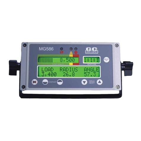
GREER Company MicroGuard 586 User manual

MicroGuard® 586
Retrofit
Rated Capacity Indicator Systems
Calibration
Testing


MG586 Calibration i W458199 Rev C 06/07
Table of Contents
Introduction......................................................................................................................................................................................... 1
Required Tools................................................................................................................................................................................... 2
Number Conversion ................................................................................................................................................................ 2
Operator’s Display Console.......................................................................................................................................................... 3
Warning/Alarm Indicators.................................................................................................................................................. 3
Display Windows....................................................................................................................................................................... 3
Push Buttons .............................................................................................................................................................................. 4
System Operation............................................................................................................................................................................. 5
System Self-Test........................................................................................................................................................................ 5
Configuration Selection.......................................................................................................................................................... 6
Normal Operation..................................................................................................................................................................... 7
Approaching Overload............................................................................................................................................................ 8
Maximum Capacity and Overload ..................................................................................................................................... 8
Two-Block Warning.................................................................................................................................................................. 9
Alarm Override........................................................................................................................................................................... 9
Adjusting the Contrast ........................................................................................................................................................ 10
Preliminary Checks and Measurements............................................................................................................................ 11
Miscellaneous Dimensions................................................................................................................................................ 11
Boom Pivot Dimensions...................................................................................................................................................... 12
Boom Hoist Cylinder Dimension ..................................................................................................................................... 13
Rope Dimensions................................................................................................................................................................... 13
Stowed Jib Dimensions....................................................................................................................................................... 14
Installation Checks ................................................................................................................................................................ 14
Installing the Reel-Off Cable............................................................................................................................................... 15
Adjusting the Extension Sensor ...................................................................................................................................... 16
Entering Calibration Data .......................................................................................................................................................... 17
00 Information........................................................................................................................................................................ 19
01 Crane Data........................................................................................................................................................................ 21
02 Dimensions........................................................................................................................................................................ 25
03 Angle Sensor.................................................................................................................................................................... 26
04 Extension Sensor............................................................................................................................................................ 27
05 Pressure............................................................................................................................................................................. 28
06 Radius/Moment............................................................................................................................................................. 31
07 Deflection ........................................................................................................................................................................... 36

MG586 Calibration ii W458199 Rev C 06/07
08 Calibrate Fly ...................................................................................................................................................................... 38
09 Stowed Jibs....................................................................................................................................................................... 40
10 Digital Input ....................................................................................................................................................................... 42
11 Angle Rate......................................................................................................................................................................... 43
Appendix A - Troubleshooting ................................................................................................................................................. A-1
System Fault Messages ................................................................................................................................................... A-1
Computer Replacement.................................................................................................................................................... A-3
Extension Reel Voltage Checks ..................................................................................................................................... A-4
Appendix B - Computer Troubleshooting........................................................................................................................... B-1
Computer Internal Status Indicators ......................................................................................................................... B-1
Power Indicator States and Actions............................................................................................................................ B-2
Communication Indicator ................................................................................................................................................ B-2
Start-up Problems................................................................................................................................................................ B-3
System Schematic ............................................................................................................................................................... B-4
Terminal Block Positions and Functions.................................................................................................................... B-5
Suggested Swing Connections....................................................................................................................................... B-6
Appendix C - Measurement Record .................................................................................................................................... C-1
Main Boom Testing Worksheet..................................................................................................................................... C-6
Attachment Testing Worksheet.................................................................................................................................... C-8
Fraction to Decimal Conversion Chart .................................................................................................................... C-13

MG586 Calibration 1 W458199 Rev C 06/07
Introduction
Congratulations on choosing the new MicroGuard®586 Retrofit Rated Capacity Indicator System.
This manual describes the calibration process for the MicroGuard®Retrofit Rated Capacity Indicator
System (hereinafter referred to as “the system”) in an on-site environment and assumes that there
is no prior knowledge of the geometry of the crane other than data provided by the manufacturer.
This document also assists personnel in obtaining necessary measurements for calibration and in
maintaining a record of the measurements and test results for review and/or comparison when
changes are made. Recording measurements and test results during the calibration process will
ensure an organized and easy to follow calibration.

MG586 Calibration 2 W458199 Rev C 06/07
Required Tools
1/4” nut driver or T15 Torx driver•
Digital or bubble level calibrated and accurate to 0.1° at level•
100 foot measuring tape - fiber type graduated in tenths of feet•
.9 1 ft .1 .2
10 11 1 ft 1 2 3
1.0′
1′-0″ 1′-1″ 1′-23/4″
1.1′ 1.23′
Note: The computer calculates measurements in feet and tenths of a foot, so having the
correct measure will facilitate entering measurements.
Digital volt/Ohm Meter capable of measurements to three decimal places•
Number Conversion
If you are using a standard tape measure, the measurement must be converted into feet and tenths
of a foot. For example: a distance of 35’–6” would be entered into the system as 35.5 feet. Whole
inches can be easily converted by dividing by 12 (6/12=.5). Fractions of an inch are converted
by dividing the numerator by the denominator. For example: 1/4 inches would be entered as .25
(1/4=.25). Conversion of whole inches and fractions of an inch (for example 6-1/4”) are converted
by first converting the fraction to a decimal and then dividing by 12. In this case 6-1/4” is converted
to 6.25 and then divided by 12 which equals 0.520. Refer to the Fraction to Decimal Conversion
Chart on page C-5
When entering weights, the number must be converted by moving the decimal three places to the
left. For example: a weight of 1,400 pounds would be entered as 1.4, and a weight of 300 pounds
would be entered as .300.

MG586 Calibration 3 W458199 Rev C 06/07
Operator’s Display Console
Warning/Alarm Indicators
The red two-block lamp will illuminate when
a two-block condition occurs (see “Two-
Block Warning” on page 8).
The yellow pre-warning lamp will
illuminate at 90% of rated capacity (see
“Approaching Overload” on page 8).
When the load reaches or exceeds 100%
of rated capacity, the red overload warning
lamp will illuminate along with the yellow
pre-warning lamp (see “Maximum Capacity
and Overload” on page 8).
Display Windows
The current rated capacity for the crane in
the current configuration will be displayed
in the rated capacity window as well as
the percent of rated capacity shown as a
meter which progresses to the right as the
load increases (see “Normal Operation” on
page 7).
The setup codes are shown in the setup
code window, as well as the parts-of-line,
and the stowed jib option if available (see
“Configuration Selection” on page 6).
The information window shows crane
specific information regarding boom length,
boom angle, and working radius, along with the load on hook. In addition, information regarding any
warnings or alarms will be displayed in this window. If the system has any internal faults, it will display
“!WARNING! SYSTEM FAULT” in the information window. The specific fault messages can be viewed
by pressing the UP ARROW or DOWN ARROW key (see “System Fault Messages” on page A-1).
Two-Block Pre-Warning Overload and Fault
Rated Capacity Setup Code
Information

MG586 Calibration 4 W458199 Rev C 06/07
Push Buttons
The setUP key enables the operator to
configure the system to match the actual
setup of the crane. Codes are present for:
• stowed jib attachments; if no
stowed options are available, this
code will not appear
• crane configuration
• number of parts-of-line
The AlARm OveRRiDe (cANcel) key is
used to disable the audible warning and
to override the function kick-out for the
current alarm condition. It is also used to
exit a menu or routine.
The cONtRAst keys are used to adjust the
lightness or darkness of the display area.
The DisPlAy mODe/select keys are used to switch to different display formats showing various
combinations of boom angle, boom length, and radius. They can also be used as an UP ARROW or
DOWN ARROW key to scroll through menu selections.
Setup
Contrast Display Mode
Select
Alarm
Override

MG586 Calibration 5 W458199 Rev C 06/07
System Operation
System Self-Test
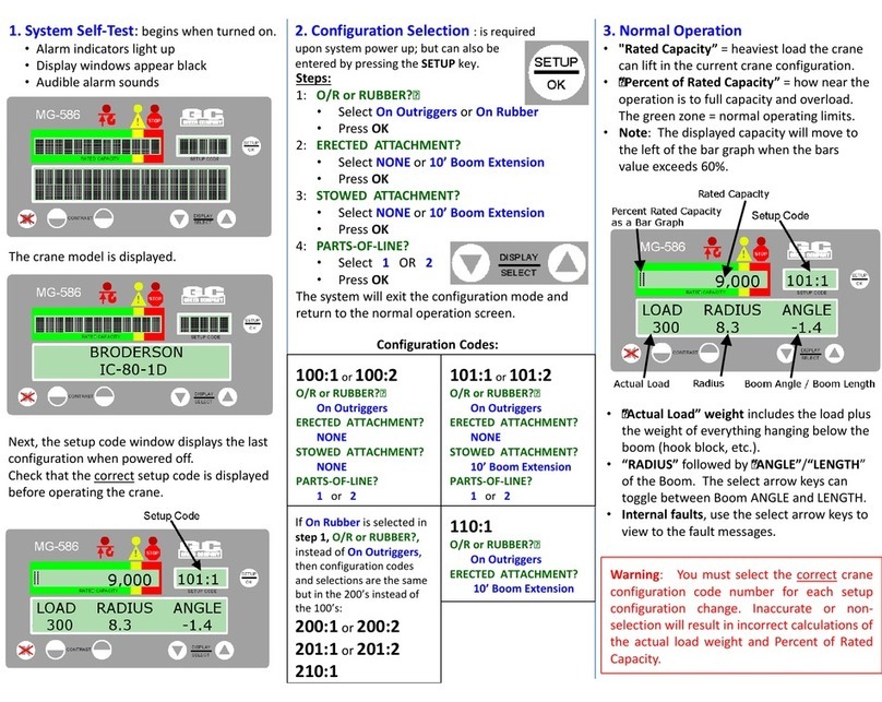
When the system is turned on, it goes through a brief self-testing process.
All three alarm indicators will light up, all display
windows will appear black, and the audible
alarm will sound.
The information display will then show the
crane model and capacity chart number for the
system configured.
Following self-test, the system will go into the setup mode. The setup code window will display the
same setup code used when the system was last powered off. Check that the correct setup code
is displayed before operating the crane. Refer to “Configuration Selection” on page 6 for code setup
instructions.

MG586 Calibration 6 W458199 Rev C 06/07
Configuration Selection
Configuration selection is required upon system power up; however, it can also be entered anytime by
pressing the setUP key.
The first selection is fo the jib. Since no jibs are
stowed, the system defaults to the main boom.
Press the setUP/Ok key to continue.
The next selection is for the number of parts-
of-line.
To change the number of parts-of-line, press
the UP ARROW or DOWN ARROW key to
change the number and press the setUP/Ok
key to continue.
Note: Some configurations allow only single
part-of-line operation. In these cases, the whole
parts-of-line selection phase will be skipped and
the parts-of-line will be set to one (1).
Once the correct parts-of-line are entered, the
system will exit the configuration mode and return to the normal working screen.
Setup Code
Parts of Line

MG586 Calibration 7 W458199 Rev C 06/07
Normal Operation
Rated Capacity
Percent of Rated
Capacity
Actual Load Boom Angle Boom Length
Percent of rated capacity indicates how near the operation is to full capacity and overload. The
percent of rated capacity meter progresses to the right as the percentage increases. As long as
the meter remains within the normal (green-bordered) zone, the percent of rated capacity is within
normal operating limits. When the percent of rated capacity exceeds 60%, the rated capacity text will
move to the left (see “Approaching Overload” on page 8).
Rated capacity is the heaviest load that the crane can lift in the current crane position and
configuration. This value may be limited by the number of parts-of-line selected.
The actual load appears in the information window under the word “LOAD”. The actual load includes
the weight of the load plus the weight of everything hanging below the boom tip (hook block, etc.).
The boom angle appears in the information window under the word “ANGLE”. This shows the current
angle of the boom in degrees and tenths of a degree. Depending on the operation, the “ANGLE”
display will change to “RADIUS”, in which case the radius from the centerline of rotation to the center
of the suspended load will be shown in feet and tenths of a foot.
The boom length is displayed in the information window under the word “LENGTH”. This shows the
current length of the boom in feet and tenths of a foot. By pressing the UP ARROW or DOWN ARROW
key, the display can be changed to show “ANGLE” or “RADIUS”.
If the system has any internal faults, it will display “!WARNING! SYSTEM FAULT” in the information
window. The specific fault messages can be viewed by pressing the UP ARROW or DOWN ARROW key
(see “System Fault Messages” on page A-1).
mWARNING
THE OPERATOR MUST SELECT THE CORRECT CRANE CONFIGURATION CODE NUMBER
FOR EACH SETUP CONFIGURATION CHANGE. INACCURATE OR NON-SELECTION OF
THE APPROPRIATE CODE NUMBER WILL RESULT IN INCORRECT CALCULATIONS AND
READINGS OF THE ACTUAL LOAD WEIGHT AND PERCENT OF RATED CAPACITY. REFER TO
“CONFIGURATION SELECTION” ON PAGE 6.

MG586 Calibration 8 W458199 Rev C 06/07
Approaching Overload
Pre-Warning Lamp
The system continuously monitors the weight of the load suspended below the boom head. The
system compares this information with rated capacity data stored within the computer.
When the rated capacity of the configuration reaches 90%, the percent of rated capacity meter
progresses from the normal (green-bordered) zone into the caution (yellow-bordered) zone.
A pre-warning lamp will illuminate and an audible alarm will beep continuously. The message
“!WARNING! – PRE-ALARM” will flash in the information window.
Maximum Capacity and Overload
Overload Lamps
When the rated capacity of the crane reaches 100%, the percent of rated capacity meter moves
from the caution (yellow-bordered) zone into the warning (red-bordered) zone.
The overload lamps will illuminate and an alarm will sound continuously. The message “!WARNING! –
OVERLOAD” will flash in the information window.
Crane motions (boom extend, boom down, and winch up) are cut in order to prevent damage to the
crane and the endangerment of persons near the lifting area.

MG586 Calibration 9 W458199 Rev C 06/07
Two-Block Warning
Two-Block Lamp
If the hook block is on a collision course with the head machinery at the end of the boom, the two-
block lamp will illuminate and an audible alarm will sound continuously. The message: “!WARNING!
TWO BLOCKING” will appear in the information window.
Crane motions (boom extend, boom down, and winch up) are cut in order to prevent damage to the
crane and the endangerment of persons near the lifting area.
Alarm Override
Alarm Override
The alarm override button is used to temporarily disable current audible alarm conditions and to
disable the automatic motion cutout. The audible alarm will sound again following any subsequent
overload or two-block conditions, or any other alarm conditions.
To disable the audible alarm, press the AlARm OveRRiDe key. Continue to hold the button down for
five (5) seconds to cancel any existing motion cuts. The AlARm OveRRiDe key must be held down to
continue overriding the motion cut.
mWARNING
THE ALARM OVERRIDE BUTTON SHOULD BE USED WITH CAUTION. AUTOMATIC AUDIBLE
ALARMS WARNING AGAINST OVERLOAD, TWO-BLOCK DANGERS, AND HAZARDOUS TIPPING
CONDITIONS ARE TEMPORARILY SILENCED WHEN THIS OPTION IS ACTIVATED. MOTION
CUTOUT MAY ALSO BE DISCONTINUED.

MG586 Calibration 10 W458199 Rev C 06/07
Adjusting the Contrast
Changes in temperature and lighting conditions may require adjustment of the display contrast.
Use the cONtRAst keys to lighten or darken the display as required.
Lighter Darker

MG586 Calibration 11 W458199 Rev C 06/07
Preliminary Checks and Measurements
The following pages provide a list of measurements that must be recorded and double-checked for
accuracy. If measurements exist in the system from a previous application, or if no measurements
exist, they must be entered into the system. Any data supplied by the crane manufacturer in the
crane application data sheet stored in the system must be validated before calibration begins. All
dimensions entered into the computer must be in feet and tenths of a foot.
Miscellaneous Dimensions
Swing Offset
Sheave Radius
Centerline of
Rotation
Swing Offset – The horizontal distance between the center of the boom pivot and the centerline of
rotation.
Note: If the centerline of rotation is ahead of the boom pivot as shown in the illustration, the
dimension will be negative. Make sure to indicate a positive (+) or negative (-) value when noting the
measurement.
Sheave Radius – The distance between the center and the outside edge of the bottom sheave.
USE THE SPACE PROVIDED IN APPENDIX C TO RECORD THE MEASUREMENTS.

MG586 Calibration 12 W458199 Rev C 06/07
Boom Pivot Dimensions
Boom Pivot
Boom Hoist Cylinder
Main Boom
Boom Hoist Cylinder
Upper Pivot
Boom Hoist Cylinder
Lower Pivot
H
L
G
J
The boom should be in a horizontal position (0°) when taking the following measurements. Use the
space provided in Appendix C to record the measurements:
Dimension “L” – The horizontal distance between the center of the boom pivot and the center of the
boom hoist cylinder upper pivot.
Dimension “J” – The vertical distance between the center of the boom pivot and the center of the
boom hoist cylinder upper pivot.
Note: If the Boom Pivot is above the boom hoist cylinder upper pivot the dimension is or negative.
Dimension “G” – The horizontal distance between the center of the boom pivot and the center of the
boom hoist cylinder lower pivot.
Dimension “H” – The vertical distance between the center of the boom pivot and center of the boom
hoist cylinder lower pivot.
USE THE SPACE PROVIDED IN APPENDIX C TO RECORD THE MEASUREMENTS.

MG586 Calibration 13 W458199 Rev C 06/07
Boom Hoist Cylinder Dimension
M
Dimension “M” –This is the distance measured around the outside of the cylinder rod, divided by 12.
USE THE SPACE PROVIDED IN APPENDIX C TO RECORD THE MEASUREMENTS.
Rope Dimensions
Rope
Boom Pivot
W
Dimension “W” – The distance between the center of the boom pivot and the winch rope
perpendicular to the rope. Measure at a low angle of <20° and a high angle of >60°.
USE THE SPACE PROVIDED IN APPENDIX C TO RECORD THE MEASUREMENTS.

MG586 Calibration 14 W458199 Rev C 06/07
Stowed Jib Dimensions
G
T
Balanced Pick Point =
Center of Gravity
Main Boom Jib Assembly
IMPORTANT!
JIB MEASUREMENTS MAY BE TAKEN WITH THE JIB STOWED, HOWEVER JIB MUST BE
REMOVED PRIOR TO BOOM CALIBRATION.
USE THE SPACE PROVIDED IN APPENDIX C TO RECORD THE MEASUREMENTS.
Installation Checks
Check wiring and EPROM installations (on page
B-4 for wiring schematic).
Check swing switches, if fitted. Use the digital
monitor screen (located under Menu 10 –
Digital Inputs) to ensure that the switches
operate properly (on page B-5).

MG586 Calibration 15 W458199 Rev C 06/07
Installing the Reel-Off Cable
IMPORTANT!
THE REEL-OFF CABLE MUST BE PROPERLY PRE-TENSIONED. THIS PROCEDURE KEEPS THE
CABLE TAUT AT ALL TIMES, WITH CONTROLLED, STEADY EXIT FROM THE EXTENSION REEL.
Pre-Tension Steps
Fully retract the boom.1.
Slowly rotate the extension reel clockwise until a “click” is heard, indicating that the clutch2.
inside the reel is engaged.
Turn the extension reel counterclockwise five (5) complete rotations.3.
Note: A temporary marker placed on the Extension Reel can facilitate the rotation count.
The reel must be restrained from turning farther while enough cable is taken off the drum to4.
reach the boom tip. (3 wraps = 10 ft.) Then the cable must be tied off at the boom tip (strain
relieved).
Pretension is complete.5.
Cable path to
boom head
First cable guide
Center point of
extension reel
Main base section of boom
Inside edge of first
cable guide must
always align with
outside edge of
extension reel.
Outside edge of
extension reel
First cable guide
must be at least
four (4) feet from
center point of
extension reel.
≥ 4”- 0”
1.

MG586 Calibration 16 W458199 Rev C 06/07
Adjusting the Extension Sensor
With the level on the boom reading 0°, rotate the extension sensor arm outward to disengage1.
the gear.
Extension Sensor
Sensor Arm
Rotate the sensor arm
outward in this direction
to disengage the gear.
Extension
Sensor Gear
Rotate the extension sensor clockwise until the end of the pot is reached. Then, continue to2.
rotate (applying more force) to cause the clutch to slip (this is usually identified by a click).
Rotate the sensor exactly 1/2 turn counter-clockwise to establish a proper voltage signal.3.
Refer to “Extension Reel Voltage Check” on page A-4. After achieving the proper voltage
setting , the Zero may be established by the calibration routine on page 27.
With the boom still level, measure the voltage of the angle sensor, refer to “Extension Reel4.
Voltage Check” on page A-4. After achieving the proper voltage setting , the Zero may be
established by the calibration routine on page 26.
Note: This check should be performed on older model cranes in the event the sensor has5.
been removed and reinstalled, or repositioned incorrectly.
Other manuals for MicroGuard 586
3
Table of contents
Other GREER Company Touch Panel manuals

GREER Company
GREER Company MicroGuard User manual

GREER Company
GREER Company MICROGUARD 424 User manual

GREER Company
GREER Company MG-534 Use and care manual

GREER Company
GREER Company MicroGuard 511 Retrofit Instruction Manual

GREER Company
GREER Company MicroGuard 586 User manual

GREER Company
GREER Company MICROGUARD 424 User manual

GREER Company
GREER Company MicroGuard 586 User manual