Greifzug Tirak Series User manual

tirak™
Electrically driven rope traction hoists for wire ropes for passenger transportation
Elektrisch angetriebene Seildurchlaufwinden für Drahtseile zur Personenbeförderung
Treuils électriques à défilement continu pour câbles métalliques pour le transport de personnes
Elektrisch aangedreven kabeldoorlooplieren voor draadkabels voor het personentransport
Model series /
Typenreihe /
Série /
Serie
L 500 P
Model series /
Typenreihe /
Série /
Serie
X 300 P
X 400 P
X 500 P
X 820 P
X 1030 P
Model series /
Typenreihe /
Série /
Serie
X 2050 P
Original assembly instructions for
incomplete machines
Notice de montage d’origine pour les
machines incomplètes
Original-Montageanleitung für
unvollständige Maschinen
Originele montagehandleiding voor
onvolledige machines

tirak™
EN-DE-FR-NL–II G920.3 - 02/2011
Technical Data / Technische Daten / Données techniques / Technische gegevens
All components are compiled and delivered on an order-specific basis. Please observe the additional information in the order
specifications and order drawing, in particular the dimensions and weights.
Alle Bauteile werden auftragsspezifisch zusammengestellt und geliefert. Bitte beachten Sie die zusätzlichen Angaben in der
Bestellspezifikation und der Bestellzeichnung, insbesondere Abmaße und Gewichte.
Toutes les pièces sont fabriquées et livrées conformément à la commande. Veuillez tenir compte des informations supplémentaires de
la spécification de commande et de la désignation pour la commande, en particulier les dimensions et les poids.
Alle componenten worden orderspecifiek samengesteld en geleverd. Let op de aanvullende gegevens in de bestelspecificatie en de
besteltekening, in het bijzonder op maten en gewichten.
tirak™ rope
Hoist7) 8)
Maximimum
working load5)
Wire rope speed
Connection
Power
Nominal current
Diameter
Minimum
breaking load6)
Weight
Dimensions / unit size
(Fig. 2)
Temperature
range4)
Noise2)
tirak™ Seil
Winde7) 8)
Maximale Betriebslast5)
Seilgeschwindigkeit
Anschluss
Leistung
Nennstrom
Durchmesser
Mindestbruchkraft6)
Gewicht
Abmessungen /
Einbaumaße
(Abb. 2)
Temperaturbereich4)
Geräuschentwicklung2)
tirak™ câble
Treuil7) 8)
Capacité de charge
maximale de
fonctionnement5)
Vitesse du câble
Branchement
Puissance
Courant nominal
Diamètre
Effort de rupture
minimal6)
Poids
Dimensions /
Cotes de montage
(Fig. 2)
Plage de température4)
Emission sonore2)
tirak™ kabel
Lier7) 8)
maximale bedrijfslast5)
Kabelsnelheid
Aansluiting
Vermogen
Nominale stroom
Diameter
Min. breukkracht6)
Gewicht
Afmetingen / inbouwmaten
(Afb. 2)
Temperatuurbereik4)
Geluidsontwikkeling2)
a b c x/y
kg m/min
230 V
50 Hz
400 V
50 Hz
kW A
mm
kN
kg
mm mm mm mm
°C dB
(A)
X 300 P 9 – x 0,5 2 28 437
X 301 P 9 x – 0,5 4,8 29 476
X 302 P 18 – x 1,1 3 28 437
X 303 P 9/18 – x 0,5/0,9 2,2/4,4 29 447
X 304 P 4,5 – x 0,25 1,1 29 437
X 305 P 4,5/9 – x 0,22/0,45 1,5/1,6 29 447
X 300 P4)
X 306 P
300
4,5/18 – x 0,2/0,9 1,2/3,7
8
23,5
29 447
272 285
~ 250 / 250
-10
…
+50
3)
72
X 400 P 9 – x 0,75 2,5 29 437
X 401 P 9 x – 0,9 5,7 32 496
X 402 P 18 – x 1,5 3,8 30 452
X 403 P 9/18 – x 0,75/1,5 2,2/4,5 31 452
265 285
~ 250 / 250
72
X 404 P 4,5 – x 0,45 1) 1) 1) 1) 1) 1) 1)
X 405 P 4,5/9 – x 0,45/0,9 1) 1) 1) 1) 1) 1) 1)
X 400 P
X 406 P
400
4,5/18 – x 0,45/1,5 1)
8
31,4
1) 1) 1) 1) 1)
-15
…
+70
1)

tirak™
G920.3 - 02/2011 EN-DE-FR-NL–III
tirak™ rope
Hoist7) 8)
Maximimum
working load5)
Wire rope speed
Connection
Power
Nominal current
Diameter
Minimum
breaking load6)
Weight
Dimensions / unit size
(Fig. 2)
Temperature
range4)
Noise2)
tirak™ Seil
Winde7) 8)
Maximale Betriebslast5)
Seilgeschwindigkeit
Anschluss
Leistung
Nennstrom
Durchmesser
Mindestbruchkraft6)
Gewicht
Abmessungen /
Einbaumaße
(Abb. 2)
Temperaturbereich4)
Geräuschentwicklung2)
tirak™ câble
Treuil7) 8)
Capacité de charge
maximale de
fonctionnement5)
Vitesse du câble
Branchement
Puissance
Courant nominal
Diamètre
Effort de rupture
minimal6)
Poids
Dimensions /
Cotes de montage
(Fig. 2)
Plage de température4)
Emission sonore2)
tirak™ kabel
Lier7) 8)
maximale bedrijfslast5)
Kabelsnelheid
Aansluiting
Vermogen
Nominale stroom
Diameter
Min. breukkracht6)
Gewicht
Afmetingen / inbouwmaten
(Afb. 2)
Temperatuurbereik4)
Geluidsontwikkeling2)
a b c x/y
kg m/min
230 V
50 Hz
400 V
50 Hz
kW A
mm
kN
kg
mm mm mm mm
°C dB
(A)
X 500 P 9 – x 0,9 3 41 489 285
X 501 P 9 x – 0,9 7 49 556 291
X 502 P 18 – x 1,8 5,5 44 504 285
X 503 P 9/18 – x 0,9/1,8 3/5 51 550 315
X 504 P 4,5 – x 0,5 2,3 49 489 285
X 505 P 4,5/9 – x 0,5/0,9 3,3/3,6 51 550 315
X 500 P4)
X 506 P
500
4,5/18 – x 0,45/1,8 2,0/5,5
8
39,2
50 550
297
315
~ 250 / 250
-10
…
+50
3)
70
X 520 P 9 – x 0,9 3 41 489 285
X 521 P 9 x – 0,9 7 49 556 291
X 522 P 18 – x 1,8 5,5 44 504 285
X 523 P 9/18 – x 0,9/1,8 3/5 51 550 315
X 524 P 4,5 – x 0,5 2,3 49 489 285
X 525 P 4,5/9 – x 0,5/0,9 3,3/3,6 51 550 315
X 520 P
X 526 P
500
4,5/18 – x 0,45/1,8 2,0/5,5
9
39,2
50 550
297
315
~ 250 / 250
-10
…
+50
3)
70
L 500 P 9 – x 0,9 2,5 30 457 290
L 501 P 9 x – 0,85 6,4 35 489 290
L 502 P 18 – x 1,8 3,8 33 472 290
L 503 P 9/18 – x 0,9/1,8 3/5 40 492 320
L 504 P 4,5 – x 0,5 2,3 35 457 290
L 505 P 4,5/9 – x 0,5/0,9 2,4/2,6 35 492
283
320
L 500 P
L 506 P
500
4,5/18 – x 0,45/1,8 1)
8
39,2
1) 1) 1) 1)
~ 250 / 250
-15
…
+70
72
X 820 P 9 – x 1,5 5 47 525 297 285
X 821 P 9 x – 1,6 10 47 582 300 285
X 822 P 18 – x 3,6 8,8 49 563 300 315
X 823 P 9/18 – x 1,5/3,0 4,5/8,7 53 563 300 315
X 824 P 4,5 – x 0,9 4,2 47 550 297 315
X 825 P 4,5/9 – x 0,75/1,5 3,2/4,4 53 563 300 315
X 820 P
X 826 P
800
4,5/18 – x 0,75/3,0 3,8/10
9
62,8
53 605 324 315
~ 250 / 250
-10
…
+50
3)
70

tirak™
EN-DE-FR-NL–IV G920.3 - 02/2011
tirak™ rope
Hoist7) 8)
Maximimum
working load5)
Wire rope speed
Connection
Power
Nominal current
Diameter
Minimum
breaking load6)
Weight
Dimensions / unit size
(Fig. 2)
Temperature
range4)
Noise2)
tirak™ Seil
Winde7) 8)
Maximale Betriebslast5)
Seilgeschwindigkeit
Anschluss
Leistung
Nennstrom
Durchmesser
Mindestbruchkraft6)
Gewicht
Abmessungen /
Einbaumaße
(Abb. 2)
Temperaturbereich4)
Geräuschentwicklung2)
tirak™ câble
Treuil7) 8)
Capacité de charge
maximale de
fonctionnement5)
Vitesse du câble
Branchement
Puissance
Courant nominal
Diamètre
Effort de rupture
minimal6)
Poids
Dimensions /
Cotes de montage
(Fig. 2)
Plage de température4)
Emission sonore2)
tirak™ kabel
Lier7) 8)
maximale bedrijfslast5)
Kabelsnelheid
Aansluiting
Vermogen
Nominale stroom
Diameter
Min. breukkracht6)
Gewicht
Afmetingen / inbouwmaten
(Afb. 2)
Temperatuurbereik4)
Geluidsontwikkeling2)
a b c x/y
kg m/min
230 V
50 Hz
400 V
50 Hz
kW A
mm
kN
kg
mm mm mm mm
°C dB
(A)
1,8 (1,95) 5,5
X 1030 P 9 – x 2,2 5,3 47 525 297 285
X 1031 P 9 x – 2,0 14 47 582 300 315
X 1032 P 18 – x 3,6 9 53 563 300 315
X 1033 P 9/18 – x 1,8/3,6 5,5/9 58 563 300 315
X 1034 P 4,5 – x 1,0 1) 1) 1) 1) 1)
X 1035 P 4,5/9 – x 0,9/1,8 3,5/4,8 58 563 300 315
X 1030 P
X 1036 P
1000
4,5/18 – x 0,9/3,6 3,8/10
10
78,5
58 605 324 315
~ 250 / 250
-15
…
+70
70
X 2050 P 6 – x 2,6 6,2 100 664 400 357
X 2051 P 6 x – 2,3 1) 1) 1) 1) 1)
X 2052 P 12 – x 5,5 12 117 664 400 372
X 2053 P 6/12 – x 3,0/6,0 11/12 120 680 400 442
X 2054 P 3 – x 1,6 6,2 100 664 400 357
X 2055 P 3/6 – x 1,6/3,0 1) 1) 1) 1) 1)
X 2056 P 3/12 – x 1,6/6,0 1) 1) 1) 1) 1)
X 2050 P
X 2058 P
2000
18 – x 7,5 17
14
157
117 664 400 372
~ 250 / 0
-15
…
+70
78,5
Table/Tabelle/Tableau/Tabel 1
1) Devices on request
2) at a distance of 1 m
3) Expanded temperature range on request
4) x) Depending on the ambient conditions (ambient temperature, sunrays, etc.) as well as the possible thermal discharge (dirt, accumulated heat, etc.)
5) With mechanical load limiting device: The load limit can be set in a range from 90 to 125% of the hoist's maximum working load. Special versi-ons available upon
request.
6) Calculation of the required minimum breaking load Foof the rope (does not correspond to the actual, manufacturer-specific minimum breaking load!)
F
o= Zpx S
F
o= 8 x S [kg] x 9,81 [N/mm²]
Fo: smallest guaranteed breaking load of the wire rope
Zp: = 8: Expansion coefficient of the wire rope
S: maximum static load on the wire rope (maximum working load of the hoist)

tirak™
G920.3 - 02/2011 EN-DE-FR-NL–V
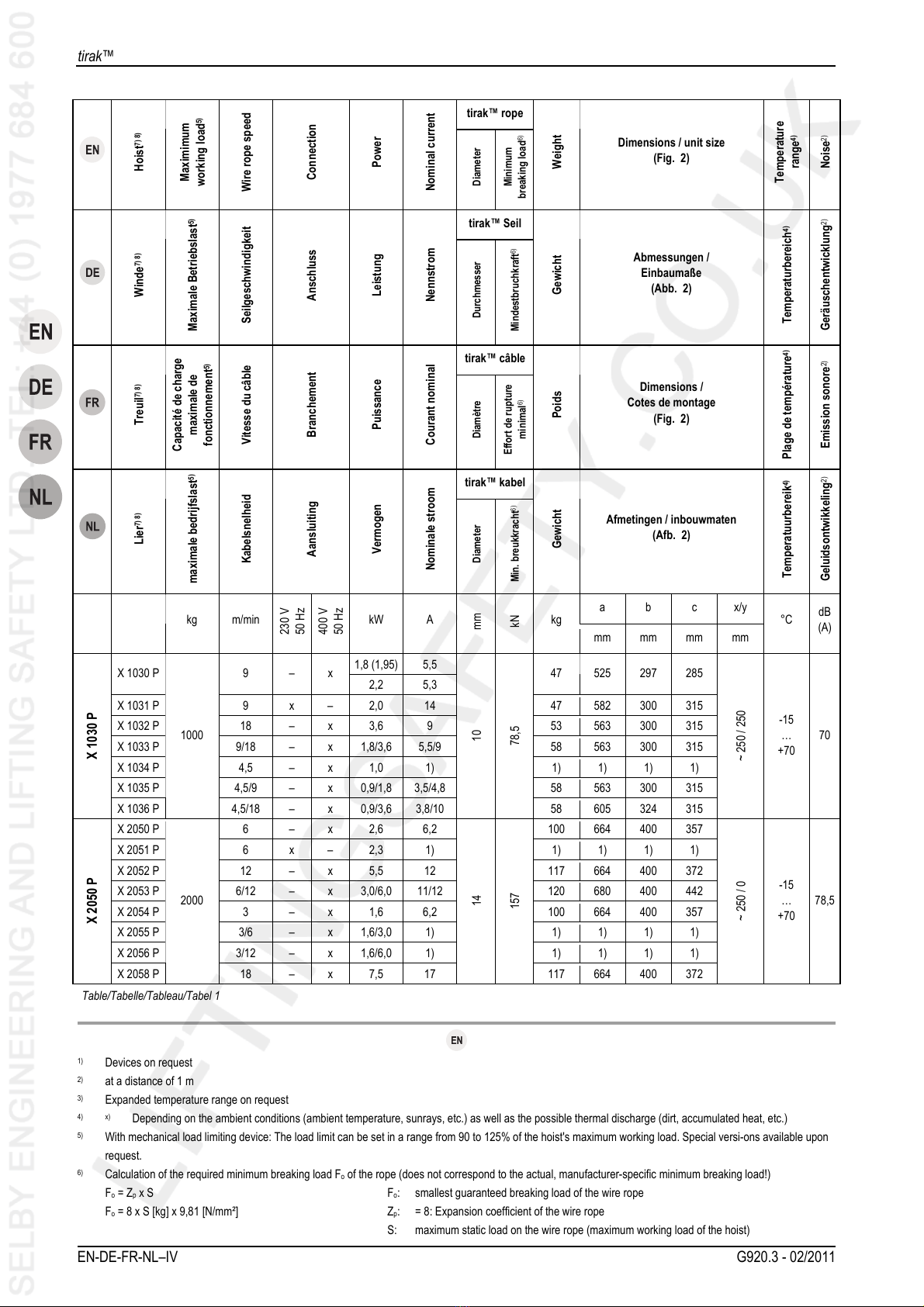
7) In accordance with DIN 15020 the devices correspond to drive group 1 Bmat rope speeds of up to 9 m/min, and to drive group 1 Cmat a rope speed exceeding 9
m/min. The average operating time per day with relation to a year (operating time class) depends on the actual load (load spectrum).
8) Optional for manual emergency operation with hand crank
1) Geräte auf Anfrage
2) in 1 m Abstand
3) erweiterter Temperaturbereich auf Anfrage
4) Abhängig von den Umgebungsbedingungen (Umgebungstemperatur, Sonneneinstrahlung, etc.) sowie der möglichen Wärmeabfuhr (Schmutz, Stauwärme, etc.)
5) Mit mechanischer Hubkraftbegrenzung: Die Hubkraftbegrenzung kann im Bereich von 90 bis 125% der maximalen Betriebslast der Winde eingestellt werden.
Sonderausführungen auf Anfrage.
6) Berechnung der erforderlichen Mindestbruchkraft Fodes Seiles (entspricht nicht der tatsächlichen, herstellerspezifischen Mindestbruchkraft!)
F
o= Zpx S
F
o= 8 x S [kg] x 9,81 [N/mm²]
Fo: kleinste garantierte Bruchlast des Drahtseils
Zp: = 8: Ausnutzungskoeffizient des Drahtseils
S: maximale statische Zuglast im Drahtseil (maximale Betriebslast der Winde)
7) Geräte entsprechen gemäß DIN 15020 bei Seilgeschwindigkeiten bis 9 m/min der Triebwerksgruppe 1 Bm, über 9 m/min Seilgeschwindigkeit der
Triebwerksgruppe 1 Cm. Die mittlere Laufzeit je Tag bezogen auf ein Jahr (Laufzeitklasse) ist abhängig von der tatsächlich auftretenden Belastung (Lastkollektiv).
8) Optional für manuellen Not-Betrieb mit Handkurbel
1) Appareils sur demande
2) A une distance de 1 m
3) Extension de la plage de température sur demande
4) En fonction des conditions ambiantes (température ambiante, exposition à la lumière du soleil, etc.) et de l'évacuation de la chaleur possible sur le site (saleté,
accumulation de chaleur, etc.)
5) Avec limitation mécanique de la force de levage : La force de levage peut être limitée sur une plage de 90 à 125% de la capacité de charge maximale de
fonctionnement du treuil. Modèles spéciaux sur demande.
6) Calcul de l’effort de rupture mininal requis Fodu câble (ne correspond pas à l’effort de rupture minimal effectif et spécifique du fabricant!) :
F
o= Zpx S
F
o= 8 x S [kg] x 9,81 [N/mm²]
Fo: Charge de rupture minimale garantie du câble métallique
Zp: = 8: Coefficient d’utilisation du câble métallique
S: Charge statique maximale du câble métallique (capacité de charge maximale de
fonctionnement du treuil)
7) Appareils conformément à DIN 15020 pour les vitesses de défilement du câble jusqu'à 9 m/min dans la catégorie de mécanismes de treuil 1 Bm, vitesse de
défilement du câble supérieure à 9 m/min dans la catégorie de mécanismes de treuil 1 Cm. La durée de vie moyenne par jour rapportée à un an (classe de durée
de vie) est fonction de la charge réelle sur le câble (spectre de charge).
8) En option pour le mode de secours manuel avec la manivelle à main.
1) Apparaten op aanvraag
2) op 1 m afstand
3) uitgebreid temperatuurbereik op aanvraag
4) Afhankelijk van de omgevingsfactoren (omgevingstemperatuur, zonnestraling etc.) en van de mogelijke warmteafvoer (vuil, warmtestuwing etc.).
5) Met mechanische hefkrachtbegrenzing: De hefkrachtbegrenzing kan worden ingesteld in een bereik van 90 tot 125% van de maximale bedrijfslast van de lier.
Speciale uitvoeringen op aanvraag.
6) Berekening van de minimum breukkracht Fovan de kabel (komt niet overeen met de daadwerkelijke fabrikantspecifieke min. breukkracht!)
F
o= Zpx S
F
o= 8 x S [kg] x 9,81 [N/mm²]
Fo: kleinste gegarandeerde breuklast van de draadkabel
Zp: = 8: Belastingscoëfficiënt van de draadkabel
S: maximale statische treklast in draadkabel (maximale bedrijfslast van de lier)
7) Apparaten voldoen volgens DIN 15020 bij kabelsnelheden tot 9 m/min aan de eisen van de drijfwerkgroep 1 Bm, boven 9 m/min kabelsnelheid aan de eisen van
drijfwerkgroep 1 Cm. De gemiddelde looptijd per dag gerelateerd aan een jaar (looptijdklasse) is afhankelijk van de daadwerkelijk optredende belasting (collectieve
belasting)
8) Optioneel voor handmatige noodwerking met handkruk

tirak™
EN-DE-FR-NL–VI G920.3 - 02/2011
Hoist Filling quantity (transmission oil) Oil type
Winde Füllmenge (Getriebeöl) Ölsorte
Treuil Quantité de remplissage (huile pour engrenages) Type d’huile
Lier Vulhoeveelheid (transmissieolie) Oliesoort
X 300 P1) 1,4 l Aral HYP85W-140, -10...+50 °C
SAE85W-140-GL5
X 400 P2) 1,4 l Klübersynth GH6 460, -15...+70 °C
CLPPG / PGLP ISO VG 460
X 500 P - X 820 P1) 2,0 l Aral HYP85W-140, -10...+50 °C
SAE85W-140-GL5
L 5002) 1,4 l Klübersynth GH6 460, -15...+70 °C
CLPPG / PGLP ISO VG 460
X 1030 P2) 2,0 l Klübersynth GH6 460, -15...+70 °C
CLPPG / PGLP ISO VG 460
X 2050 P2) 5,0 l Klübersynth GH6 460, -15...+70 °C
CLPPG / PGLP ISO VG 460
Table/Tabelle/Tableau/Tabel 2
1) Oil drain plug with socket head screw (mineral oil) / Ölablassschraube mit Innensechskant (mineralisches Öl) / vis de vidange d'huile à six pans creux (huile
minérale) / olieaftapschroef met inbus (minerale olie)
2) Oil drain plug with hexagon head screw (synthetic oil) / Ölablassschraube mit Sechskant (synthetisches Öl) / vis de vidange d'huile à six pans (huile synthétique) /
olieaftapschroef met zeskant (synthetische olie)
Rope weight
Seilgewichte
Poids des câbles
Kabelgewichten
Rope design
Konstruktion des Seils
Construction du câble
Constructie van de kabel
Nominal diameter
Nenndurchmesser
Diamètre nominal
Nominale diameter
Standard
Standard
Standard
Standaard
Rotation-resistant
Drehungsarm
Antigiratoire
Verdraaiingsarm
[mm] [kg/m] [kg/m]
6 0,172 0,160
8 0,270 0,280
9 0,340 0,360
10 0,400 0,480
14 0,702 0,900
Table/Tabelle/Tableau/Tabel 3

tirak™
G920.3 - 02/2011 EN-DE-FR-NL–VII
Components / Bestandteile / Composants / Bestanddelen
Model series / Typenreihe / Série / Serie
L 500 P
Model series / Typenreihe / Série / Serie
X 2050 P
Model series / Typenreihe / Série / Serie
X 300 P / X 400 P
X 500 P / X 520 P
X 820 P / X 1030 P
Fig./Abb./Fig./Afb. 1

tirak™
EN-DE-FR-NL–VIII G920.3 - 02/2011
Fig./Abb./Fig./Afb. 2
Fig./Abb./Fig./Afb. 3
Model series /
Typenreihe /
Série / Serie
Distance / Abstand / Distance / Afstand [mm]
A1-A2
A2-A3
A1-A4
a
b
c
x
y
X 300 P
X 400 P
L 500 P
255
220
220
~250
~250
X 500 P –
X 1030 P
300
267
267
~250
~250
X 2050 P
570
360
360
Table/Tabelle/Tableau/Tabel 1
~250
~250
Screw / Schraube / Vis / Schroef
BD
Strength /
Festigkeit /
Résistance /
Sterkte
X 300 P
X 400 P
L 500 P M10 – 8.8
X 500 P –
X 1030 P M10 M16 8.8
X 2050 P
M16 M30 8.8
Table/Tabelle/Tableau/Tabel 4
Fig./Abb./Fig./Afb. 4

tirak™
G920.3 - 02/2011 EN-DE-FR-NL–IX
Fig./Abb./Fig./Afb. 5
Fig./Abb./Fig./Afb. 6
Fig./Abb./Fig./Afb. 7
Fig./Abb./Fig./Afb. 8
Fig./Abb./Fig./Afb. 9

tirak™
EN-DE-FR-NL–X G920.3 - 02/2011
Fig./Abb./Fig./Afb. 10
Fig./Abb./Fig./Afb. 11
Fig./Abb./Fig./Afb. 12
Fig./Abb./Fig./Afb. 13
Fig./Abb./Fig./Afb. 14

tirak™
G920.3 - 02/2011 EN-DE-FR-NL–XI
Fig./Abb./Fig./Afb. 15
Fig./Abb./Fig./Afb. 16
Fig./Abb./Fig./Afb. 17
Fig./Abb./Fig./Afb. 18

tirak™
EN-DE-FR-NL–XII G920.3 - 02/2011

Installation manual
G920.3 - 02/2011 EN-1
Contents
1General ............................................................................... 2
1.1 Terms and abbreviations used in this manual .......... 2
1.2 Symbols used in this manual .................................... 3
2Safety.................................................................................. 3
2.1 General safety instructions ....................................... 3
2.2 Instructions for the operator...................................... 4
2.3 System manufacturer's responsibilities..................... 5
3Overview............................................................................. 5
3.1 Delivery state ............................................................ 5
3.2 Scope of delivery ...................................................... 5
3.3 Equipment description .............................................. 5
4Description......................................................................... 7
4.1 Functional description............................................... 7
4.2 Components / Modules............................................. 8
4.3 Technical Specifications ........................................... 8
4.4 Operating fluids......................................................... 8
4.5 Circuit diagram.......................................................... 8
4.6 Safety equipment...................................................... 8
4.7 Anchoring.................................................................. 9
4.8 Load limits................................................................. 9
5Ropes.................................................................................. 9
6Optional accessories......................................................... 9
7Options ............................................................................... 9
8Necessary accessories ..................................................... 9
9Installation and commissioning..................................... 10
9.1 Directives and standards ........................................ 10
9.2 Checks to be undertaken
before starting installation....................................... 10
9.3 Assembly ................................................................ 11
9.4 Commissioning ....................................................... 12
10 Operating / Operation...................................................... 13
10.1 Checking before starting work ................................ 13
10.2 Operation ................................................................ 13
10.3 Emergency descent ................................................ 14
10.4 Operate using the hand crank................................. 14
10.5 Switching off when overloaded ............................... 15
11 Foreseeable misuse ........................................................ 15
12 Dismantling ...................................................................... 15
13 Shutting down.................................................................. 15
13.1 Permanently decommissioning............................... 15
14 Transport and storage .....................................................16
14.1 Transport .................................................................16
14.2 Storage....................................................................16
15 Maintenance work ............................................................16
15.1 Authorized maintenance personnel .........................16
15.2 Mandatory inspections.............................................16
15.3 Reading the running hours counter .........................17
15.4 Care and maintenance ............................................17
15.5 Adjustment...............................................................18
15.6 Ordering spare parts................................................19
16 Disposal and environmental protection.........................19
17 Troubleshooting...............................................................20
18 Declaration of incorporation (excerpt)...........................23
DANGER!
Risk of injury caused by falling objects, malfunctions,
incorrect usage and incorrect operation!
Failure to follow these instructions:
can result in severe injuries or death,
can result in damage to the equipment.
–Read through this operating manual carefully before you
install and commission this machine.
–Follow the instructions and procedures specified in this
manual in order to ensure safe operation of the equip-
ment.

Installation manual
EN-2 G920.3 - 02/2011
1General
Date of issue
02/2011
Copyright
The copyright of this instruction manual remains with Greifzug
Hebezeugbau GmbH.
This instruction manual is intended only for the operators of the
systems described here and their staff. This instruction manual
must be available to the operating personnel at all times. Addi-
tional copies can be obtained on request.
No part of this instruction manual may be reproduced, distributed
or otherwise communicated without the permission of Greifzug
Hebezeugbau GmbH.
Legal proceedings may be implemented in the case of any in-
fringements.
Manufacturer's address
Sales and service office:
Greifzug Hebezeugbau GmbH
Scheidtbachstraße 19-21
51469 Bergisch Gladbach, Germany
Postfach 20 04 40
51434 Bergisch Gladbach, Germany
Tel: +49 (0) 22 02 / 10 04-0
Fax: +49 (0) 22 02 / 10 04-50 + 70
Greifzug Hebezeugbau GmbH reserves the right to make
changes to the product described in this instruction manual as
part of their ongoing product improvement programme.
Customers can obtain documentation about other TRACTEL
products by requesting the documentation from companies within
the TRACTEL Group or service organisations appointed by the
TRACTEL Group. Please visit our TRACTEL website at:
www.tractel.com for further details regarding the hoisting gear
and related accessories; stationary or mobile working platforms
for moving around on the inside and outside of buildings; rigging;
block stops for heavy loads; personal safety harnesses to pre-
vent falls; traction and rope tension measuring equipment, etc.
The TRACTEL Group and its dealer network also provide addi-
tional customer and repair services upon request.
1.1 Terms and abbreviations used in
this manual
The terms used in this instruction manual have the following
meanings:
System / Machine
Pursuant to the Machine Directive 2006/42/EC lifting equipment,
hoisting gear, safety equipment and rigging for lifting are re-
garded as machines. The term "system" or "machine" also de-
scribes the device in which the unit described here will be fitted.
System manufacturer
The system manufacturer (system planner, system manufacturer,
installer) is the company marketing the system and all of the
required components. The system manufacturer is responsible
for the design, manufacturing, assembly and marketing.
Rigging
Rigging consists of equipment which does not belong to the
hoisting gear and which creates a connection between the carry-
ing means and the load or the carrying means and the load lifting
equipment (e.g. rope loops, round slings, shackles, swivel hooks,
eye hooks, deflection rollers).
Anchoring point
Part of the on-site suspended construction to which the suspen-
sion rope, the safety rope, deflection rollers and the hoisting gear
are anchored separately from one another.
Actuation
The independent secondary brake is triggered (EMERGENCY
STOP situation) by manual actuation or uncontrolled actuation
resulting from vibrations.
Operating personnel
Personnel who have been trained by the operator to operate the
product and are authorised to operate it.
Operating personnel (PAM)
An appointed person who has undergone the appropriate ad-
vanced training for working at heights and who, due to his knowl-
edge and practical experience, is in the position to perform the
required operating tasks when provided with the necessary
instructions.
Operator
The operator is responsible for the correct operation of the sys-
tem / equipment and also for adhering to the maintenance inter-
vals and the undertaking of the service work.
Running hours
The running hours are the effective operating times of a hoist's
motor.
Electrician
An electrician is someone who possesses sufficient knowledge
or has obtained the required qualification through training in
order to recognise the risks and avoid the dangers that can occur
when working with electricity.
Emergency stop
The independent secondary brake is triggered (emergency stop
situation, e.g. overspeed) in the event of a suspension cable
rupture or a hoist malfunction.
Independent secondary brake
A device for stopping the load lifting equipment in the event of
the suspension rope snapping or a malfunction, e. g. drive mal-
function.
Overall suspended load
The overall suspended load is the actual suspended static load,
which is made up of the payload, the load lifting equipment's own

Installation manual
G920.3 - 02/2011 EN-3
weight, the additional fittings, the wire ropes and the control and
connection cables.
Hoisting gear / machine for lifting loads
Device or equipment consisting of a device with load carrying
means for lifting or transporting loads (e.g. wire rope hoist or wire
rope hoist with rope and swivel hook).
Customer / end customer
The customer or end customer is the system manufacturer's
customer and can also be the operator.
Load lifting equipment (LAM)
A component or piece of equipment which does not belong to the
hoisting gear, which enables the load to be grasped and which is
attached between the machine and the load or to the load itself,
or is intended to be an integral component of the load. Rigging
and its components are also regarded as load lifting equipment.
Material lifting equipment (MAM)
Load lifting equipment for material.
Maximum working load
The maximum working load specifies the maximum load the
device is allowed to bear. The maximum working load is speci-
fied on the nameplate.
Payload
The payload is the load that is raised, pulled or held in place by
the device. If reeving is used according to the block and tackle
principle then the payload may exceed the maximum working
load. The maximum working load must never be exceeded by
using reeving.
Personnel lifting equipment (PAM)
Personnel lifting equipment. Combined material and personnel
lifting equipment also counts here.
Specialist
An appointed person who has undergone the appropriate training
and who, due to his knowledge and practical experience, is able
to safely perform the required work when provided with the nec-
essary instructions.
Products in contact with the rope
Products in contact with the rope include hoists, deflection rollers,
independent secondary brakes and other products that the rope
runs through or is in contact with.
tirak™
tirak™ is used in the text as the abbreviation for the hoist.
Carrying means
The carrying means is equipment connected to the hoisting gear
for attaching load lifting equipment, rigging or loads (e.g. a hook
permanently attached to the suspension rope).
Maintenance personnel
A person appointed by and trained by Greifzug Hebezeugbau
GmbH with a valid certificate, who is capable of safely performing
the required maintenance, inspection and service work when
provided with the required instructions.
1.2 Symbols used in this manual
DANGER!
Type and source of danger
Result: e.g. death or severe injuries.
–Measures that must be taken to eliminate the danger.
ATTENTION!
Type and source of danger
Result: e.g. equipment or environmental damage.
–Measures that must be taken to eliminate any possible
damage.
Note:
This s
y
mbol is not used to indicate safet
y
information but to
indicate information that will give you a better understanding o
f
the working procedures.
This symbol identifies devices for transport o
f
material.
This s
y
mbol identifies devices for transportin
g
people and materials.
2Safety
2.1 General safety instructions
DANGER!
Danger of severe injuries caused by malfunctions, incor-
rect use and incorrect operation!
–You must abide by the following instructions in order to
ensure safe operation and correct functioning of the
equipment!
–Please observe the special safety instructions for all of
the work to be performed as described in the individual
chapters in this manual.
–Never use faulty or damaged products, accessories or
rigging.
–Never use ropes that are not the specified original ropes
approved for the application. Abide by the details about the
rope type and diameter.

Installation manual
EN-4 G920.3 - 02/2011
–Rope, products in contact with the rope and rigging must not
be soiled by heavily soiling building materials such as con-
crete, epoxy resin or other adhesive materials. Protect the
products against soiling! Always use brush attachments to
clean the wire rope in an extremely dirty environment.
–Abide by the rope's withdrawal criteria, see '15.4 Care and
maintenance, Rope' on page 17.
–Clean regularly.
–Check that all of the screw connections are tight.
–Change any damaged parts or have them repaired by a
specialist. Repairs are only to be carried out by a specialist
workshop or by personnel from Greifzug Hebezeugbau
GmbH.
–Never use a high pressure cleaner to clean the rope or
products in contact with the rope! Penetrating moisture will
result in malfunctions and damage to mechanical installa-
tions (e.g. brakes, ball bearings) and the electrical equip-
ment.
–Dirt on the wire rope will result in premature wear or the
corrosion of the wire rope, rigging and products in contact
with the rope.
–Do not lubricate the rope using a lubricant that contains
disulfide (e. g. Molycote®).
–You must abide by the safety specification sheets issued by
the manufacturer of the lubricant being used.
–Abide by the instructions concerning transport, storage and
cleaning listed on page 16.
–The anchoring devices must comply with the instructions
given in this manual or the applicable directives / standards.
–The permitted working load must never be exceeded.
–Motors can become hot whilst working. Never touch the
motors.
–Operation without plugs on the motor (Position 3, see
Fig. 16) is prohibited. Moisture can impair the effectiveness
of the brake. Risk of injury on the exposed motor shaft.
–Working outdoors during lightning or a storm is prohibited.
Danger of lightning strikes or the load being tipped over by
gusts of wind.
–Local climate and weather conditions must always be taken
into consideration during the planning stages: If in doubt,
you must request the weather and wind forecast from the
meteorological office before beginning work.
–Maintenance and repair work must only be undertaken by
authorised service personnel, see '15.1 Authorized mainte-
nance personnel' on page 16.
–Self-locking nuts must never be reused and they must al-
ways be exchanged for new ones.
–Only qualified personnel who have been trained on the
system are permitted to install and operate it in compliance
with the instructions given in this instruction manual.
–Private users are obliged to obtain training in the assembly,
operation and maintenance of the unit by Greifzug He-
bezeugbau GmbH.
–Only qualified electricians or trainees supervised by a quali-
fied electrician are permitted to undertake work on the elec-
trical equipment in accordance with the electro technical
standards, rules and regulations.
–The electric connection must be implemented as described
in '9.3 Assembly, Electrical connection' on Page 11 in order
to avoid electrical hazards.
–Never stand beneath suspended loads. Cordon off the
dangerous area whenever necessary. Support and secure
caught or jammed loads.
–Never grasp the wire rope while the machine is operating.
–Never reach into the inlet or outlet of rope contacting de-
vices whilst the machine is operating. There is a risk of be-
ing pulled in and crushed.
–Hearing protection may be necessary, depending on how
the hoist is installed.
–If the load cannot be guided by on-site means then a rota-
tion-resistant wire rope with a swivel hook or a rope swivel
must be used.
–When performing welding work the national safety and
accident prevention regulations must be observed (e.g.
BGR159 in Germany).
2.2 Instructions for the operator
–If more than one person is entrusted with the tasks men-
tioned above then the operator must appoint a supervisor
who is authorised to issue instructions.
–The operator is also responsible for preparing clear operat-
ing, maintenance, repair and other working instructions and
ensuring that the unit is operated correctly by instructing and
training the personnel in the correct and approved utilisation
methods.
–Attached warning signs and information signs must be
readable at all times. Missing or illegible warning signs and
information signs must be replaced immediately.
–The operator is responsible for the correct operation of the
system as well as for adhering to the maintenance periods
and the undertaking of the service work.
–A minimum weight is always required for an emergency
descent.
–The operator or the system manufacturer must ensure that
the payload can be traversed against the static friction in a
manual emergency descent in any situation (e.g. if the rope
is reeved) and that the maximum working load is not ex-
ceeded.
–The operator is committed to maintaining the logbook sup-
plied with the system.
–EU Directive 89/391/EEC applies within the European Union
(in Germany Betriebssicherheitsverordnung (BetrSichV)).
You must always abide by your country's national accident
prevention regulations.
–You must provide suitable protective equipment such as
safety gloves, hearing protectors and a fall prevention sys-
tem. Protection against extreme weather conditions (e.g.
sun protection, protection against cold) are also considered
to be part of the personal protective equipment.

Installation manual
G920.3 - 02/2011 EN-5
–Always ensure that the workplace is sufficiently lit.
–This instruction manual and the instruction manuals for all of
the accessory parts must be handed out to all of the author-
ised personnel. The documents must be available at all ti-
mes.
–As Greifzug Hebezeugbau GmbH does not know the appli-
cations that the product described here will be used for in
the future, the system operator is therefore committed to in-
forming their personnel about any new safety instructions as
well as any supplementary maintenance work.
–The system operator is responsible for selecting the anchor-
ing method and suitable rigging options.
–The anchoring devices must comply with the instructions
given in this manual or the applicable directives / standards.
–Safe operation is not guaranteed if non-original spare parts
are utilised. This applies, in particular, to the use of ropes
other than the specified original ropes approved for the ap-
plication. Guarantee claims against the manufacturer will be
invalidated and this will also invalidate the CE approval for
any product holding this approval.
–Adhere to the permitted temperature range, see Table 1 on
page II.
2.3 System manufacturer's responsibili-
ties
–The system manufacturer is responsible for the design,
manufacture, assembly and marketing as well as obtaining
the CE seal of approval and issuing the EU Declaration of
Conformity.
–The products contained in the package supplied by Greifzug
Hebezeugbau GmbH must be carefully selected by the sys-
tem manufacturer, be used in the approved manner and in-
stalled in compliance with the instructions given in this in-
stallation and operating manual.
–The information and notes contained in this installation and
operating manual must be integrated into the system manu-
facturer's operating manuals and documentation and sup-
plemented by the addition of system specific details (e.g.
blockages and malfunction procedures). Merely handing this
manual over to the operator is insufficient.
–If necessary, a test report must be included, in which the
static and dynamic tests that were run are described in de-
tail.
–Instructions regarding the maintenance of the product and
its accessories must be integrated in the system's mainte-
nance manual.
3Overview
3.1 Delivery state
The equipment is delivered fully assembled.
3.2 Scope of delivery
yHoist in accordance with the order specifications
yOriginal Installation manual
yCircuit diagram
yLogbook
yTest certificate
yInstallation declaration
3.3 Equipment description
Authorized utilization
Hoist
The hoist is intended for raising and lowering personnel lifting
equipment as well as combinations of personnel and load lifting
equipment.
Never use ropes that are not the specified original ropes ap-
proved for the application. Abide by the details about the rope
type and diameter.
Hoists for manual emergency operation with hand crank may
only be operated with the hand crank in emergencies (power
failure, rescue).
The rope infeed is on the motor side (observe the arrow on the
casing!). This corresponds to the load side of the hoist. The rope
outfeed is on the unloaded side of the hoist. The unloaded side
of the hoist may be loaded with a maximum of 100 kg (e.g. via
the rope pre-tensioning).
Product purpose
The product is intended for commercial as well as private use.
The precise intended use will be defined by the operator or the
equipment manufacturer.
Swivel pulleys, hooks, shackles and eyes and other optional
carrying devices belonging to the product are only to be used
together with this product.
If the load cannot be guided by on-site means then a rotation-
resistant wire rope with a swivel hook or a rope swivel must be
used.
Maintenance and repair work must only be undertaken by author-
ised service personnel, see '15.1 Authorized maintenance per-
sonnel' on page 16.

Installation manual
EN-6 G920.3 - 02/2011
Health and safety requirements
Greifzug Hebezeugbau GmbH declares that the machine de-
scribed in this instruction manual complies with technological
safety standards that were applicable to the equipment in the
European Union when it was launched on the market by the
manufacturer.
Test reports (test certificates) are included with the product. The
static and the dynamic tests are described in detail in the test
reports.
The system manufacturer / operator is therefore responsible for
selecting and equipping the hoists with mechanical load lifting
devices whenever necessary in compliance with the valid direc-
tives and standards and for staying within the hoist's application
limits for the specific application.
Commissioning the machine is prohibited until the machine in
which this is installed complies as a whole with the regulations of
the 2006/42/EC Directive, the corresponding national legislation
for implementing the regulations in accordance with national law
and the corresponding declaration of conformity has been issued.
yThe operator or system manufacturer must perform a risk
evaluation in accordance with Appendix I of the guideline
2006/42/EC for machines for raising loads. EN 14492-1
must also be taken into account when inspecting the equip-
ment.
yA conformity evaluation process must be run by the operator
or the system manufacturer on machines used for lifting
personnel or personnel and goods, which come under Ap-
pendix IV No. 17 of Directive 2006/42/EC, in accordance
with Article 12, Paragraphs 3 or 4 of Directive 2006/42/EC.
EN 1808 must also be taken into account when inspecting
the equipment.
Guarantee and liability exclusions
See '11 Foreseeable misuse' on page 15.
Any use other than that described here will be considered to be
unauthorised. Greifzug Hebezeugbau GmbH does not accept
any liability for damages resulting from unauthorised use. The
operator must assume sole responsibility in this case. Abiding by
all of the instructions given in this instruction manual, in particular
the installation and maintenance regulations, are also considered
part of authorised use.
Application areas
The product is suitable for use under the following operating
conditions:
yFor permanent or temporary installations
yFor short-term operation: Drive groups see Table 1 on
page II.
yAt heights of up to 1,000 m above sea level (max)
yPermitted temperature range see Table 1 on page II
DANGER!
Danger of severe accidents!
–24-hour operation is prohibited.
–Use in areas where there is a risk of explosion is prohib-
ited.
–Use in a corrosive environment is prohibited.1)
–Use in close proximity to open fire or in an extremely hot
environment is prohibited.
1) Corrosion protection in accordance with order specifications
Installation example
See Fig. 8.
Structural requirements
General information
You must abide by the payload limit specified for the hoisting
gear, deflection roller, rigging and anchoring points. See
'4.8 Load limits' on Page 9.
Personnel lifting equipment must be equipped with an independ-
ent secondary brake, which secures the load, for example, on a
safety rope against falling.
If the load cannot be guided by on-site means then a rotation-
resistant wire rope with a swivel hook or a rope swivel must be
used.
Rope, products in contact with the rope and rigging must not be
soiled by heavily soiling building materials such as concrete,
epoxy resin or other adhesive materials. Protect the products
against soiling! Always use brush attachments to clean the wire
rope in an extremely dirty environment.
Anchoring point
The structural equipment to be used for attaching the product
must be designed in compliance with the applicable Directives
and standards (see '9.1 Directives and standards' on Page 10).
The application's overall suspended load must be taken into
account regarding the design of the suspended construction. The
overall suspended load is the actual suspended static load,
which is made up of the payload, the load lifting equipment's own
weight, the additional fittings, the wire ropes and the control and
connection cables.
If necessary, a test report must be included, in which the static
and dynamic tests that were run are described in detail.
Drive path
During lifting processes the drive path must be limited by one or
multiple limit switches, so that the upward and/or downward
movement is stopped.
The operator or the system manufacturer must determine the
design and the fitting position of the limit switches when taking
their risk assessment into account.

Installation manual
G920.3 - 02/2011 EN-7
The gap between the limit switch and the wire rope anchoring or
the protruding components must be chosen so that the machine
can be switched off reliably and in good time. We recommend
that you use a minimum gap (Size a) of between 0.5 to 1.5 m.
See Fig. 12 (example).
The wire rope must be long enough so that the rope end connec-
tion or the load bearing point or the rope end itself cannot be
pulled up to or into the product or the accessory parts.
Operating equipment
The hoist must be protected with an Emergency Off button so
that the hoist can be stopped immediately in dangerous situa-
tions.
It must be possible to position the operating equipment in such a
way that safe operation is always possible regardless of the
movements of the hoist.
In control systems for three-phase operation, equipment must be
provided which shuts down the system in the case of an incorrect
phase sequence, thus preventing a mix-up of the direction of
travel UP/DOWN, which could eventually disable the limit
switches and load limiter switches.
Nameplate and warning signs /application
restrictions
Replace missing or illegible nameplates and warning signs im-
mediately.
See Fig. 3.
Item Name
1 Warning sign 'Wire rope diameter'
2 tirak™ nameplate
3 Brake nameplate
4 Electric motor nameplate
5 Emergency descend warning sign
6 Rope identification
The necessary information can be obtained from the nameplate.
Directives and standards
Applicable directives and standards: See '9.1 Directives and
standards' on page 10.
Product versions covered in the manual
The product versions described in this manual are listed in
Table 1 on page II.
Running hours counter
The running hours counter is located in the hoist's terminal box.
The running hours counter counts the time in which the hoist is in
operation as running hours (UPWARD or DOWNWARD move-
ments). To read the running hours counter: See '15.3 Reading
the running hours counter' on page 17.
4Description
4.1 Functional description
The tirakTM is a hoist for the transport of persons or for persons
and materials. The hoist is operated with an electric motor.
The X-model series hoists can raise and lower as well as pull
and release in the pulling direction of the rope.
The electromagnetic spring-applied brake automatically locks
when the operating control for travelling UP or DOWN is released
or when the power fails. When lowering the load by manually
venting the spring-applied brake a centrifugal brake prevents the
rope from accelerating up to a fast speed.
The hoist's payload can be multiplied according to the block and
tackle principle by reeving the rope. See '4.8 Load limits' on
Page 9.
The hoises are equipped with a mechanical load limiting device.
The load limiting device will active automatically when the over-
load setting is reached. The hoist will be stopped. The maximum
overload that has to be set up can be found in the applicable
directives and standards (See '9.1 Directives and standards' on
Page 10).
The system manufacturer / operator is therefore responsible for
determining and setting up the application dependent maximum
overload.
For further information see '15.5 Adjustment, Adjusting the me-
chanical load limiting device' on Page 18.
Options: Hoists fitted with a hand crank for manual
emergency operation:
Hoists for manual emergency operation with hand crank may
only be operated with the hand crank in emergencies (power
failure, rescue).
The power supply is deactivated when the hand crank is in the
operating position. The load limiting device is inactive. The load
is held by a spring mechanism in the hand crank when the ser-
vice brake is released.

Installation manual
EN-8 G920.3 - 02/2011
4.2 Components / Modules
See Fig. 1.
Item Name
1 Rope
2 Plug connector for the limit switch1)
3 Brake magnet lever
4 Handle
5 Terminal box
6 Rope drive
7 Carry handle
8 Gearbox
9 Motor
Options: version fitted with a hand crank1):
15 Hand crank
16 Fixing bolt
17 Cotter pin
18 'Manual operation' switch
1) Optional scope of delivery, dependent on the hoist version and the
order specifications
4.3 Technical Specifications
The technical specifications are listed in Table 1 on page II.
4.4 Operating fluids
Transmission oil (hoist)
Transmission oil, see Table 2 on Page VI.
In normal cases, it is not necessary to change the transmission
oil.
ATTENTION!
Incorrect transmission oil!
Damage to the gearbox due to insufficient lubrication.
–Use only the lubricants specified in the table.
Synthetic oil and mineral oil may not be mixed!
–Thoroughly flush the gearbox repeatedly with the new oil
type when changing the oil type.
–Change the oil drain plug to correspond with the new oil
type (socket head screw: mineral oil; hexagon head
screw: synthetic oil).
Lubricant
Application Lubricant
Traction sheave external
teeth (only model series X
2050)
hebro-chemie VARILUB
or Klüber Grafloscon C-SG 0 Ultra
or Klüber C-SG 1000 Ultra
Quantity approx. 10 cm³ per lubrication
Rope Multipurpose oil/grease (without disul-
phide)
Axle for the hand crank Multipurpose grease
4.5 Circuit diagram
The circuit diagram is located in the terminal box of the motor.
4.6 Safety equipment
Mechanical load limiting device
The load limiting device will active automatically when the over-
load setting is reached. The hoist will be stopped.
The maximum overload that has to be set up can be found in the
applicable directives and standards (See '9.1 Directives and
standards' on Page 10).
The system manufacturer / operator is therefore responsible for
determining and setting up the application dependent maximum
overload.
For further information see '15.5 Adjustment, Adjusting the me-
chanical load limiting device' on Page 18.
Spring-applied brake
The electromagnetic spring-applied brake automatically locks
when the operating control for travelling UP or DOWN is released
or when the power fails.
Centrifugal brake
A centrifugal brake on the motor shaft of the hoist ensures that
the load is not lowered too fast when the spring-applied brake on
the hoist’s motor is released manually.
Running hours counter
The running hours can be read from the running hours counter,
in order to determine when the next hoist safety check must be
carried out.
Manual operation switch
The 'Manual operation' switch interrupts the power supply when
the hand crank is in operating position.
This manual suits for next models
57
Table of contents
Languages:
Popular Lifting System manuals by other brands

Launch
Launch TLT260AT user manual

IMER
IMER AIRONE 300 N Operating, maintenance, spare parts manual

Sealey
Sealey ES502.V2 instructions

Lockhard
Lockhard UP Lift 5 120 operating manual

Tractel
Tractel T 1000 Original Operation and Installation Manual

Ingersoll-Rand
Ingersoll-Rand Zero Gravity Air Balancer 2.0 user manual

Lift Products
Lift Products LL Series Service manual

AMGO Hydraulics
AMGO Hydraulics PRO-12 Installation and service manual

AFFORDABLE LIFTS
AFFORDABLE LIFTS KCSPM3648 Assembly and installation manual

Fantek
Fantek FT-6860 operating instructions

FIPA
FIPA TR01.250 operating instructions

Aqua Creek Products
Aqua Creek Products F-710RLA quick start guide