GREIN EFESTO4 Specification sheet

DOC N° D7B40001EE 4 May 2020 pag. 2
“EFESTO4” Multiple beams safety barrier
IMPORTANT REMARKS ON SAFETY
As this device, for the safety of operators working on dangerous machinery, it is
necessary that an authorised person should carry out the installation carefully while
making notes and maintain such records for future instruction and maintenance.
The safety light curtain forms only one link of the safety system.
Therefore, complete system performance remains the responsibility of the machine
builder or end user.
Please observe all technical details and recommendations reported in this
installation/instruction manual without exception and with strict adherence to all applicable
local, National and International Safety Standards and guidelines which may apply to the
machines.
GREIN is not responsible for any dangerous occurs to a not good employ of the
product.

DOC N° D7B40001EE 4 May 2020 pag. 3
“EFESTO4” Multiple beams safety barrier
Summary
GENERAL INFORMATIONS pag. 4
TERMS AND DEFINITIONS pag. 4
TECHNICAL CARATTERISTICS AND FUNCTIONS pag. 5
INSTALLATION GUIDELINES pag. 6
DETERMINATION OF SAFETY DISTANCE pag. 7
MINIMUM DISTANCE TO AVOID THE REFLECTIONS pag. 9
MECHANICAL MOUNTING pag. 10
GROUPING OF BARRIERS pag. 11
MASTER / SLAVE BARRIERS pag. 12
MODELS AND E FUCTION pag. 13
WIRING CONNECTIONS pag. 14
CONNECTING EXTERNAL CONTACTORS pag. 21
EMITTER CONNECTIONS AND FUNCTIONS pag. 22
RECEIVER CONNECTIONS AND FUNCTIONS pag. 22
INDICATION AND DIAGNOSTIC pag. 27
SERVICE AND TEST pag. 31
SETTING UP AND TEST pag. 32
LIST OF MODELS AND CHARACTERISTICS pag. 33
RESPONS TIME FOR MASTER / SLAVE pag. 41
BLANKING FUNCTION pag. 42
MUTING FUNCTION pag. 45
ACCESSORIES - MIRRORS pag. 47
MOUNTING BRACKETS pag. 52
CONNECTION CABLES pag. 55
INTEGRATED SIGNALLING LAMP pag. 55
RELAYS MODULE DIN RAIL pag. 56
EXTERNAL MODULES BOX pag. 57
WARRANTY pag. 61
UE DECLARATION OF CONFORMITY pag. 62

DOC N° D7B40001EE 4 May 2020 pag. 4
“EFESTO4” Multiple beams safety barrier
GENERAL INFORMATIONS
The EFESTO4 light curtain is a optoelectronic system with multi beams ( Electro-Sensitive Protective
Equipment ) type 4 for the protection of body to prevent accident on the machine on dangerous plants
in accordance with International safety standards.
EFESTO4 is formed of an emitter and a receiver unit synchronized through a optic link. The safety out-
put are at solid state with possibility to transform on power with relays inserted on special module.
The wide range of model permit the employ on every field of industrial automation supplying the
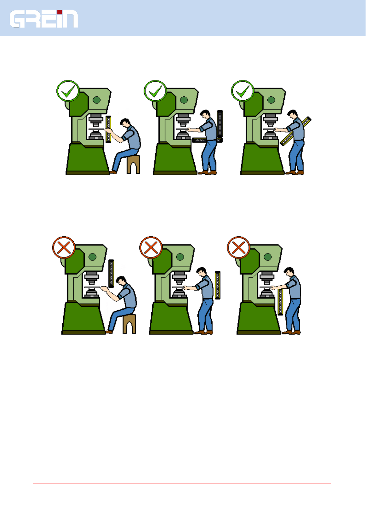
protection of the fingers, hand, arm, body, for the movement on dangerous area.
The principal application are presses, robotized areas, highly automated equipment, and many others.
The series EFESTO4 is divided in different models based on the functions implemented.
This system allows the customer to choose the most adequate model of barrier in according to his
requirements. To complete the range are available some interconnection modules to connect the
barrier without to pass to the general panel of machine.
TERMS AND DEFINITIONS
OSSD0 Safety output channel zero.
OSSD1 Safety output channel one.
OSSD STATO ON Condition on which the output permits the flow of current.
OSSD STATO OFF Condition on which the output do not permit the flow of current.
EDM External Device Monitor.
RESET OSSD restart from OFF to ON.
MUTING Temporary suspension of the safety function.
OVERRIDE Manual muting function after a mistake in automatic muting.
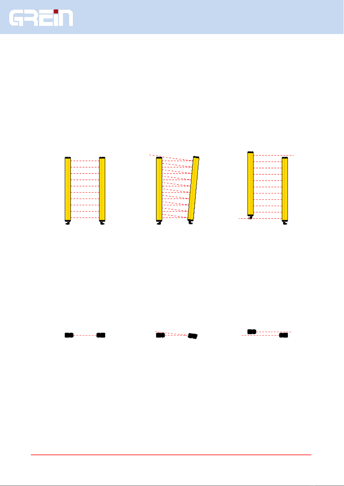
Protective height PH
It is the zone in which the test rod will stop the
barrier.
Sensitive height SH
It is the zone covered by the beams.
AActive part of the lens.
B Beam spacing in mm.
Resolution d
It is the minimum object detected on protected
area, Is the dimension necessary for the
obscuration of two adjacent beams.
d = A + B.

DOC N° D7B40001EE 4 May 2020 pag. 5
“EFESTO4” Multiple beams safety barrier
Technical characteristics
Synchronization Tx Rx Optical
Total aperture angle 5°
Wave lenght 940 nm
Resolutions 14, 20, 30, 40, 55, 65, 125, 135, 306, 315 mm
Maximum range 6 - 15 - 30 - 60m depending from the resolution
Protected height from 200 mm to 3000 mm
Maximum speed 3,3 m/s ( of test rod 150mm length )
Output 2 PNP - 500 mA short circuit and overload protected
Connections M12 5 / 8 poles or M23 17 in functions of the model and options
Power supply
24Vcc ± 10% PELV
Response time From 5 to 30ms depending to number of beams
Max connections lenght 100 m
Body Extruded aluminium, 36 x 50, RAL 1.021
IP protection degree IP 65
Relative umidity 5 - 95%
Working temperature 0 ÷ 65 °C
Safety level Ttpe 4 - SIL 3 - SILCL 3 - PL e – Cat. 4
Functions
Reset Selection of the restart of the barrier
Type Automatic or manual
Restart time 100 ms
Blanking Beams exclusion
N of beams 1, 2 or 3 beams
Type Blanking with or without the presence of the object
Selection Through wiring, are not necessary programming modules
MUTING Temporary exclusion of safety function of the barrier
Muting type Two sensors, with contemporaneity control
Muting enable Enable / disable muting function
Override Manual override of muting function
Muting lamp output Output for muting lamp, 24V 500mA max
EDM External Device Monitor
OSSD-S Output signaling of the safety outputs state
MUTE - F Output for signaling of interrupted barrier when muting active
TEST
Simulation of interruption of light curtain beams barrier, to facilitate
the monitoring of the safety of the machine
BARGRAPH 3 led for alignment and indications

DOC N° D7B40001EE 4 May 2020 pag. 6
“EFESTO4” Multiple beams safety barrier
INSTALLATION GUIDELINES
Correct Installation
frontal protection vertical and horizontal protection oblique protection
Incorrect installation
insertion into the insertion between insertion into the
danger zone under the barrier and dangerous dangerous zone above
the barrier zone the barrier
Refer to the standard EN ISO 13855 for a correct installation of the safety device

DOC N° D7B40001EE 4 May 2020 pag. 7
“EFESTO4” Multiple beams safety barrier
DETERMINATION OF SAFETY DISTANCE
Before of the installation it is necessary to calculate the safety distance in order to allow the stop of the
machine before the operator or part of his body enter in the dangerous area ( as described in EN 999
and ISO 13855 ).
Definitions:
S safety distance in mm
T1 response time of machine in ms
T2 response time of curtain in ms
(see TX / RX label)
d resolution of the system in mm
Vertical installation
Models with resolution up to 40mm
The following formula is valid for a distance S included between 100 and 500 mm:
S = 2 (T1 + T2) + 8 (d - 14)
If S results more of 500mm, use the following formula :
S = 1,6 (T1 + T2) + 8 (d-14)
Models with resolution more than 40 and up to 90 mm
S = 1,6 (T1 + T2) + 850
The highest beam must be placed at a minimum height of 900 mm from the installation plane of the
machine, while the inferior beam must be at a height less than 300 mm
Models with resolution more than 90 mm
S = 1,6 (T1 + T2) + 1.200

DOC N° D7B40001EE 4 May 2020 pag. 8
“EFESTO4” Multiple beams safety barrier
DETERMINATION OF SAFETY DISTANCE
Horizontal installation
For all types of light curtains with horizontal installation, to detect intrusion of legs and body, the
distance Sshall be calculated using formula :
S = 1,6 (T1 + T2) + K
where:
K = (1200 - 0.4 H) ) must be > 850 mm
H= height of curtain in mm from ground
Hmust be lower than the working plane, and in any case don’t higher than 1.000 mm
Example using a light curtain with resolution 50 mm height of working plane 800 mm:
T1 = 100ms
T2 = 10 ms
H= 750 mm
K= 1200 - 0.4 x 750 = 900 mm
S= 1.6 (100 + 10) + K = 1076 mm

DOC N° D7B40001EE 4 May 2020 pag. 9
“EFESTO4” Multiple beams safety barrier
MINIMUM DISTANCE TO AVOID THE REFLECTIONS
The beam angle of optic and alignment tolerance for emitter and receiver is 5 degrees. Since reflective
surfaces near the detection zone can cause reflections and therefore non-detection of an object, a
minimum distance Ato the optical axis, should be observed according to the following formula:
A = 44 L where A is in mm, Lis in m
A should never be less than 131 mm
To verify the above, after the installation of the light curtain, is necessary to pass the test rod
through the detection zone, near the emitter, the receiver and in the middle of the detection zone,
verifying that :
If selected the automatic restart the LED OS OFF should remain always ON;
If selected the manual restart the LED BMS should remain always OFF.
If the indication are not as described above, there is a hole in the detection zone due to reflection.
Modify the position of the barrier to avoid the reflection.

DOC N° D7B40001EE 4 May 2020 pag. 10
“EFESTO4” Multiple beams safety barrier
MECHANICAL ASSEMBLY
During the installation it is necessary to verify the right position of emitter and receiver in order to check
that they are in the same plane and axis as shown on the following drawings.
SIDE VIEW :
CORRECT ANGULAR MISTAKE AXIAL MISTAKE
TOP VIEW :
CORRECT ANGULAR MISTAKE AXIAL MISTAKE

DOC N° D7B40001EE 4 May 2020 pag. 11
“EFESTO4” Multiple beams safety barrier
GROUPING OF LIGHT CURTAINS
Linear assembly: to increase the protected height
To avoid the reciprocal interference between 2 light curtains it is necessary that the emitter and
receiver are mounted on opposite sides.
1) Example of two light curtains on the same axis with a non-constant resolution in the join point
2) Example of two light curtains no aligned to maintain constant resolution in the joint point.
Suggestions to avoid interference between light curtains assembled in line in case of long distances or
protected machines installed in series:
The light curtain can work on vertical position or upside-down.
Don't turn the transmitter in the opposite direction of the receiver, it changes the protected field.
Wrong Right Right

DOC N° D7B40001EE 4 May 2020 pag. 12
“EFESTO4” Multiple beams safety barrier
LIGHT CURTAINS FOR ANGLED APPLICATION
"L" SHAPE ( master and slave )
Where the safety distance is particularly long (for example using large presses) it is necessary that
nobody can enter in the dangerous area at the restart of the machine. This problem can be solved by
installing the angled version light curtain, which consists of a vertical unit (MASTER) and a horizontal
unit (SLAVE) used to stop behind protection.
The vertical light curtain is provided with one fixed cable of length max. 0.5m and a male connector.
The horizontal light curtain is provided with female connector only.
Particular attention must be taken during the installation, insuring that on the point where the light
curtains meet, the resolution must be the same as the horizontal light curtain (see drawing below).
As the two units (vertical and horizontal) works electrically as one light curtain, attention must be taken
during the installation, the system will operate only if all the vertical / horizontal - emitter / receiver are
perfectly aligned. The bargraph can help in this operation.
On this solution, the function of floating blanking is active only on vertical light curtain ( MASTER ). On
the horizontal unit ( SLAVE ) the blanking is not active and the interruption of a single beam leads OSSD
in the OFF state.
Connection Master / slave

DOC N° D7B40001EE 4 May 2020 pag. 13
“EFESTO4” Multiple beams safety barrier
Model and function
All model have the following features :
-TX with M12 4 poles connector and test input;
-RX with 2 solid state PNP output;
-Automatic reset;
-Bargraph with 3 led for alignment and signaling.
Functions and connections available of different models
Model
Function available
RX Connectors
RM
EDM
BLNK
MUTE-E
MUTE
O-S
M-F
M12 5P
M12 8P
M23-17P
EF - a ...
•
EF - b ...
•
•
•
EF - c ...
•
•
EF - d ...
•
•
•
•
•
•
EF - e ...
•
•
•
•
•
EF - f1 ...
•
•
•
•
•
•
EF - f2 ...
•
•
•
•
•
•
... optical code
Optic
optic
Resolution
Min. Range
Max range
_ _ A
14 mm
0.5
6 m
_ _ AL
20 mm
2 m
15 m
_ _ B
30 mm
0.5m
15 m
_ _ BL
40 mm
6 m
30 m
_ _ C
55 mm
0.5m
15 m
_ _ CL
65 mm
6 m
30 m
_ _ D
125 mm
0.5m
15 m
_ _ DL
135 mm
6 m
30 m
_ _ E
306 mm
0.5m
15 m
_ _ EL
315 mm
6 m
30 m
_ _ protection height
Note are available special versions __DLL and __ELL with range from 6 up to 60m
LEGEND
RM Manual reset
EDM External Device Monitoring
BLNK Blanking
MUTE-E Input for muting enable
MUTE Input of 2 external sensors + guard override + signaling lamp
O-S Output signaling the status of the safety outputs
M-F Output signaling the status of interrupted barrier during the muting state.
RECEIVER CONNECTIONS
M12-5P Connector M12 - 5 Poles - male
M12-8P Connector M12 - 8 Poles - male
M23-17P Connector M23 - 17 Poles - male

DOC N° D7B40001EE 4 May 2020 pag. 14
“EFESTO4” Multiple beams safety barrier
Wiring connection
Warning on connection cables
1 –Use cables with section of 1 mm2for length connection more than 50m.
2 –The units TX / RX shall be connect to the ground (PE).
3 –All the cables shall follow different way from those of power.
4 –The power of the barrier should be separated from that of equipment dedicated to the control
of power equipment, such as inverters.
5 –If there is the possibility to damage the cables, take care to protect them against crushing or
cutting.
6 –The cables should be shielded type, the shield should be connected to the ground ( PE ).
Emitter connection
Emitter
EF - ... -
Pin N
Wire color
Function
Description
Type
Level
M12 4 poles
1
Brown
+24V
Positive power supply
IN
+24Vdc +/- 10% 0,5A
2
White
TEST
TEST signal
IN
0 - 24 Vdc 10mA
3
Blue
GND
0V power supply
IN
0V
4
Black
PE
Ground
-
-
Example of connection

DOC N° D7B40001EE 4 May 2020 pag. 15
“EFESTO4” Multiple beams safety barrier
EF- a CONNECTION
Receiver
EF-a - ... -
Base
Pin N
Wire color
Function
Description
Type
Level
M12 5 poles
1
Brown
+24V
Positive power supply
IN
+24Vdc +/- 10% 1A
2
White
OSSD-0
Static safety output 0
OUT
0 - 24 Vdc 0,5A max
3
Blue
GND
0V power supply
IN
0V
4
Black
PE
Ground
-
-
5
Grey
OSSD-1
Static safety output 1
OUT
0 - 24 Vdc 0,5A max
Example of connection
This version does not have the control of the external
relays. The OSSD output must be connected to the
machine through a safety module or a PLC.

DOC N° D7B40001EE 4 May 2020 pag. 16
“EFESTO4” Multiple beams safety barrier
EF- b CONNECTION
Receiver
EF-b - ...
Reset + Edm
Pin N
Wire color
Function
Description
Type
Level
M12 8 poles
1
White
OSSD-0
Static safety output 0
OUT
0 - 24 Vdc 0,5A max
2
Brown
+24V
Positive power supply
IN
+24Vdc +/- 10% 1A
3
Green
START ENABLE
Selection of manual or automatic reset
IN
0 - 24 Vdc 10mA
4
Yellow
START
Input of external RESET
IN
0 - 24 Vdc 10mA
5
Gray
OSSD-1
Static safety output 1
OUT
0 - 24 Vdc 0,5A max
6
Pink
EDM
External device monitor input
IN
0 - 24 Vdc 10mA
7
Blue
GND
0V power supply
IN
0V
8
Red
PE
Ground
-
-
Example of connection

DOC N° D7B40001EE 4 May 2020 pag. 17
“EFESTO4” Multiple beams safety barrier
EF- c CONNECTION
Receiver
EF-c - ...
Blanking
Pin N
Wire color
Function
Description
Type
Level
M12 8 poles
1
White
OSSD-0
Static safety output 0
OUT
0 - 24 Vdc 0,5A max
2
Brown
+24V
Positive power supply
IN
+24Vdc +/- 10% 1A
3
Green
BLNK-0
BLANKING input 0
IN
0 - 24 Vdc 10mA
4
Yellow
BLNK-1
BLANKING input 1
IN
0 - 24 Vdc 10mA
5
Gray
OSSD-1
Static safety output 1
OUT
0 - 24 Vdc 0,5A max
6
Pink
BLNK-2
BLANKING input 2
IN
0 - 24 Vdc 10mA
7
Blue
GND
0V power supply
IN
0V
8
Red
PE
Ground
-
-
Example of connection
This version does not have the control of the external
relays. The OSSD output must be connected to the
machine through a safety module or a PLC.

DOC N° D7B40001EE 4 May 2020 pag. 18
“EFESTO4” Multiple beams safety barrier
EF- d CONNECTION
Receiver
EF-d - ...
Reset + Edm + Blanking
Pin N
Wire color
Function
Description
Type
Level
M12 8 poles
1
White
OSSD-0
Static safety output 0
OUT
0 - 24 Vdc 0,5A max
2
Brown
+24V
Positive power supply
IN
+24Vdc +/- 10% 1A
3
Green
START ENABLE
Selection of manual or automatic reset
IN
0 - 24 Vdc 10mA
4
Yellow
START
Input of external RESET
IN
0 - 24 Vdc 10mA
5
Gray
OSSD-1
Static safety output 1
OUT
0 - 24 Vdc 0,5A max
6
Pink
EDM
External device monitor input
IN
0 - 24 Vdc 10mA
7
Blue
GND
0V power supply
IN
0V
8
Red
PE
Ground
-
-
M12 5 poles
1
Brown
OSSD-S
Output signaling of the safety outputs state
OUT
0 - 24 Vdc 0,2A max
2
White
BLNK-0
BLANKING input 0
IN
0 - 24 Vdc 10mA
3
Blue
BLNK-1
BLANKING input 1
IN
0 - 24 Vdc 10mA
4
Black
BLNK-2
BLANKING input 2
IN
0 - 24 Vdc 10mA
5
Grey
nc
-
-
Example of connection

DOC N° D7B40001EE 4 May 2020 pag. 19
“EFESTO4” Multiple beams safety barrier
EF- e CONNECTION
Receiver
EF-e - ...
Reset + Edm + Muting
Pin N
Wire color
Function
Description
Type
Level
M12 8 poles
1
White
OSSD-0
Static safety output 0
OUT
0 - 24 Vdc 0,5A max
2
Brown
+24V
Positive power supply
IN
+24 Vdc +/- 10% 1A
3
Green
START ENABLE
Selection of manual or automatic reset
IN
0 - 24 Vdc 10mA
4
Yellow
START
Input of external RESET
IN
0 - 24 Vdc 10mA
5
Grey
OSSD-1
Static safety output 1
OUT
0 - 24 Vdc 0,5A max
6
Pink
EDM
External device monitor input
IN
0 - 24 Vdc 10mA
7
Blue
GND
0V power supply
IN
0V
8
Red
PE
Ground
-
-
M12 5 poles
1
Brown
GOVR-0
Guard override input 0, bypass of the muting function
IN
0 - 24 Vdc 10mA
2
White
GOVR-1
Guard override input1, bypass of the muting function
IN
0 - 24 Vdc 10mA
3
Blue
MUTE-0
Muting 0 input
IN
0 - 24 Vdc 10mA
4
Black
MUTE-1
Muting 1 input
IN
0 - 24 Vdc 10mA
5
Grey
MUTE-S
Muting lamp output
OUT
0 - 24 Vdc 0,5A max
Example of connections

DOC N° D7B40001EE 4 May 2020 pag. 20
“EFESTO4” Multiple beams safety barrier
EF - f1 / EF - f2 CONNECTION
Receiver
EF-f - ...
Reset + Edm + Muting
Pin N
Wire color
Function
Description
Type
Level
M23 17 poles
1
White
OSSD-0
Static safety output 0
OUT
0 - 24 Vdc 0,5A max
2
Brown
+24V
Positive power supply
IN
+24 Vdc +/- 10% 1A
3
Green
START ENABLE
Selection of manual or automatic reset
IN
0 - 24 Vdc 10mA
4
Yellow
START
Input of external RESET
IN
0 - 24 Vdc 10mA
5
Grey
OSSD-1
Static safety output 1
OUT
0 - 24 Vdc 0,5A max
6
Pink
EDM
External device monitor input
IN
0 - 24 Vdc 10mA
7
Blue
GND
0V power supply
IN
0V
8
Red
PE
Ground
-
-
9
Black
nc
-
-
10
Purple
OSSD-S
MUTE-F
EF f1 = OSSD-S Output signaling of the safety outputs
state
EF f2 = MUTE - F main beam interrupted when MUTING
function is activated
OUT
0 - 24 Vdc 0,2A max
11
Grey - pink
GOVR-0
Guard override input 0, bypass of the muting function
IN
0 - 24 Vdc 10mA
12
Red - blue
GOVR-1
Guard override input 1, bypass of the muting function
IN
0 - 24 Vdc 10mA
13
White - green
MUTE-0
Muting 0 input
IN
0 - 24 Vdc 10mA
14
Brown - green
MUTE-1
Muting 1 input
IN
0 - 24 Vdc 10mA
15
White - yellow
MUTE-S
Muting lamp output
OUT
0 - 24 Vdc 0,5A max
16
Yellow - brown
MUTE-E
Muting function enable
IN
0 - 24 Vdc 10mA
17
White - grey
nc
-
-
Example of connections
Table of contents
Popular Accessories manuals by other brands

Mamiya
Mamiya Universal Specifications

Bisque
Bisque Paramount ME Replacement and Troubleshooting

Lightolier
Lightolier Calculite 784 specification

Innova
Innova DISCatcher Installation

Nostalgia Electrics
Nostalgia Electrics Coca-Cola BC24COKE instruction manual

Bitspower
Bitspower BP-VG3080ASF installation guide