GREISINGER gir 2000Pt Technical document

E32.0.02.6C-07
GHM GROUP - Greisinger
GHM Messtechnik GmbH | Hans-Sachs-Str. 26 | 93128 Regenstauf | GERMANY
Mounting and Operating Manual
96x48 Panel Mount Controller
as of version 2.8
GIR 2000 Pt
Please read these instructions
carefully before use!
WEEE-Reg.-Nr. DE 93889386
Please consider the safety instructions!
Please keep for future reference!

E32.0.05.6C-07 Mounting and operating manual GIR 2000 Pt page 2 of 18
Contents
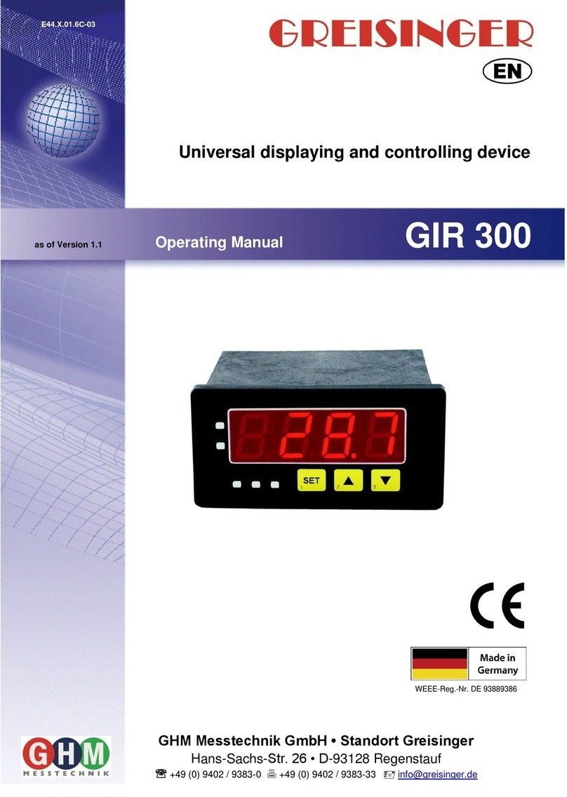
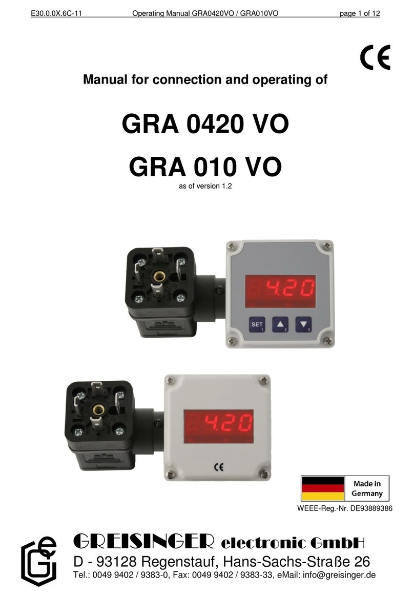
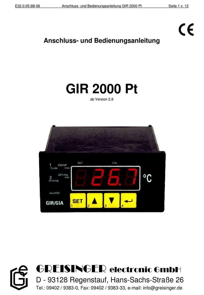
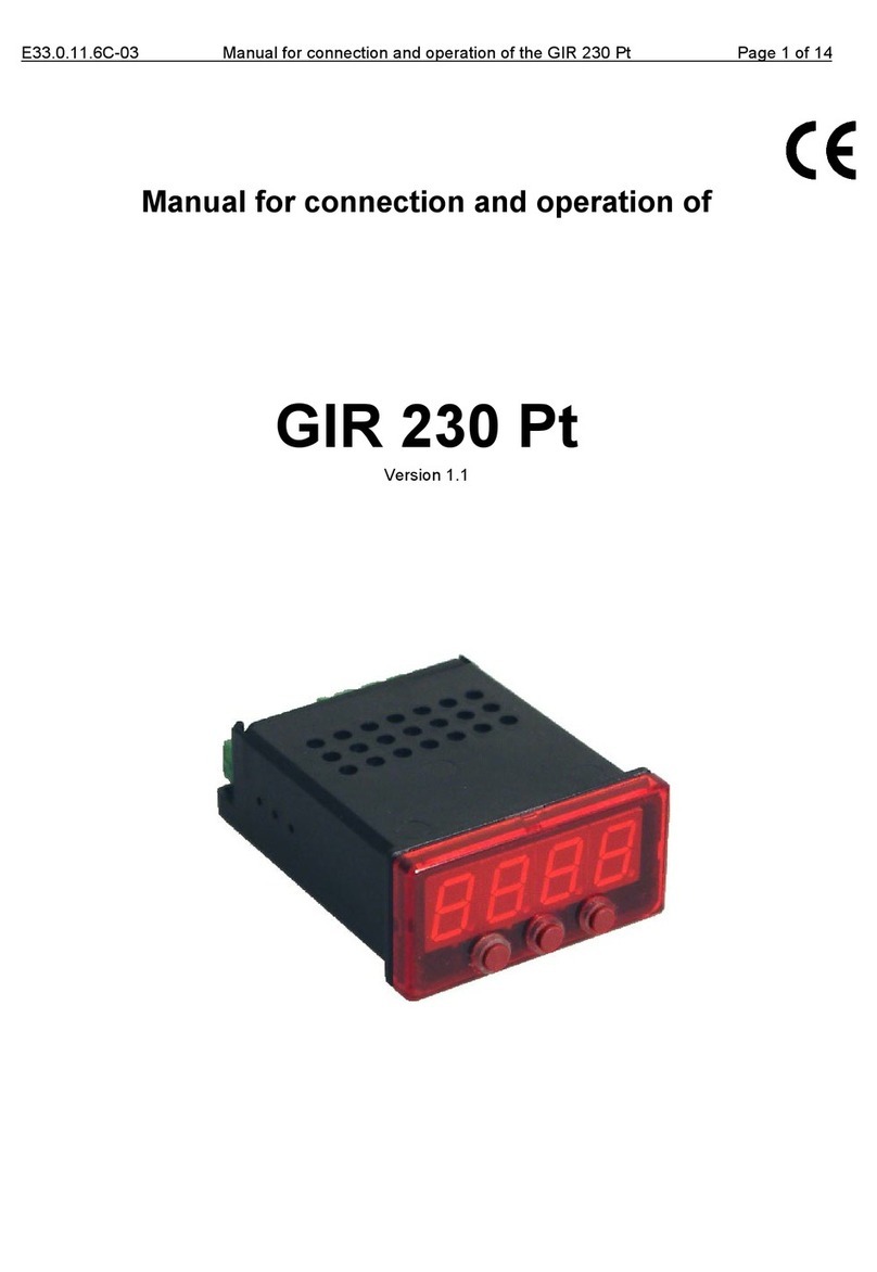
1. SAFETY ....................................................................................................................................................... 3
1.1. General note............................................................................................................................................ 3
1.2. Intended use............................................................................................................................................ 3
1.3. Skilled personnel..................................................................................................................................... 3
1.4. Type label ............................................................................................................................................... 4
1.5. Safety signs and symbols........................................................................................................................ 4
1.6. Reasonably foreseeable misuse............................................................................................................... 5
1.7. Safety guidelines..................................................................................................................................... 5
2. PRODUCT DESCRIPTION....................................................................................................................... 5
2.1. Scope of supply....................................................................................................................................... 5
2.2. Function .................................................................................................................................................. 6
3. MOUNTING IN PANELS / HOUINGS.................................................................................................... 6
4. DISPLAY AND OPERATING ELEMENTS............................................................................................ 6
4.1. Display elements..................................................................................................................................... 7
4.2. Operating elements ................................................................................................................................. 7
5. ELECTRIC CONNECTION...................................................................................................................... 8
5.1. Terminal assignment: Standard............................................................................................................... 8
5.2. Connection data ...................................................................................................................................... 8
5.3. Connecting an input signal...................................................................................................................... 8
5.4. Connecting switching outputs................................................................................................................. 9
6. CONFIGURATION OF THE MEASURING INPUT............................................................................. 9
6.1. Configuration: select filter.................................................................................................................... 10
7. CONFIGURATION OF THE OUTPUT FUNCTIONS........................................................................ 10
7.1. Selection of the output function............................................................................................................ 11
7.2. 2-point-controller.................................................................................................................................. 11
7.3. Min-/Max-Alarm................................................................................................................................... 11
8. OFFSET- AND SLOPE-ADJUSTMENT................................................................................................ 12
8.1. Menu calling and adjustment................................................................................................................ 13
9. SWITCHING POINTS AND ALARM-BOUNDARIES........................................................................ 13
9.1. Menu calling......................................................................................................................................... 14
9.2. 2-point-controller.................................................................................................................................. 14
9.3. Minimum/maximum-alarm................................................................................................................... 14
10. MIN-/MAX-VALUE MEMORY:.......................................................................................................... 15
11. ALARM DISPLAY ................................................................................................................................. 15
12. ERROR CODES...................................................................................................................................... 16
13. DECOMMISSIONING, RESHIPMENT AND DISPOSAL................................................................ 16
13.1. Decommissioning ............................................................................................................................... 16
13.2. Reshipment and disposal..................................................................................................................... 16
14. SPECIFICATION ................................................................................................................................... 17
E32.0.05.6C-07 Mounting and operating manual GIR 2000 Pt page 3 of 18
1. Safety
1.1. General note
Read this document carefully and get used to the operation of the device before you use it.
Keep this document within easy reach near the device for consulting in case of doubt.
Mounting, start-up, operating, maintenance and removing from operation must be done by quali-
fied, specially trained staff that have carefully read and understood this manual before starting any
work.
The manufacturer will assume no liability or warranty in case of usage for other purpose than the
intended one, ignoring advices of this manual, operating by unqualified staff as well as unauthor-
ized modifications to the device.
1.2. Intended use
The GIR 2000 Pt is a microcontroller based display, monitoring and controlling unit.
The devices are only to be operated in control panels ore suitable electric housings, where the
connection terminal area is sufficiently protected against touch.
They are designed for industrial or commercial use.
Outdoor installation without suitable means of protection is not allowed.
The relay output is suitable to switch electrical loads with max 10 A resistive load at up to 250 V
AC.
Prior to fulfil the referring requirements, the device has to be configured on the base of this manual.
Wrong configuration may lead to malfunction in the application. The commissioning expert / the
operator is liable for a suitable configuration.
The safety guidelines of the manual are followed!
The unit does not contain any components that you can service or repair yourself.
All the described operations are only to be performed of skilled personnel that are authorized by
the operator.
Any other use or use exceeding this is considered as non-conforming and leads to the expiration of
any liability or guarantee claims from the manufacturer.
Note: Combination / connection to other electrical equipment with CE marking does not automati-
cally deliver a conform system. A new evaluation of the system’s conformity to the low voltage di-
rective (2014/35/EU) and EMC directive (2014/30/EU) by the manufacturer may be necessary,
eventually others have to be considered (e.g. machinery directive).
1.3. Skilled personnel
The mounting, electrical installation, start of operation, maintenance and decommissioning must
only performed by a skilled electrician.
Users of the readily installed device have to be sufficiently skilled in the operation of the device and
able to avoid risks. The operator of the arrangement is responsible for sufficient qualification the
operators.

E32.0.05.6C-07 Mounting and operating manual GIR 2000 Pt page 4 of 18
1.4. Type label
Manufacturer address
Production date code
Serial number
Type
CE mark: see below
Please refer to manual: see below
Disposal: refer Chapter 13.2
Warning sign: Electrical risk, see below
Electric connections, refer chapter 5
Symbol explanation
Electrical risk:
At electrical connections and components signed with this symbol there is a
risk of electrical shock.
Please refer to manual:
Read the mounting- and operating manual carefully, before you connect and
use the device.
CE mark:
With the CE-Sign declares the manufacturer, that the Product is conform with
the prevailing requirements of EG.
1.5. Safety signs and symbols
Warnings are labelled in this document with the followings signs:
Caution!
This symbol warns of imminent danger, death, serious injuries and significant
damage to property at non-observance.
Attention!
This symbol warns of possible dangers or dangerous situations which can pro-
voke damage to the device or environment at non-observance.
Note!
This symbol point out processes which can indirectly influence operation, pos-
sibly cause incorrect measurement or provoke unforeseen reactions at non-
observance.

E32.0.05.6C-07 Mounting and operating manual GIR 2000 Pt page 5 of 18
1.6. Reasonably foreseeable misuse
1.
This device must not be used at potentially explosive areas!
Do not use these products as safety or emergency stop devices or in any other
application where failure of the product could result in personal injury or material
damage.
Failure to comply with these instructions could result in death or serious injury
and material damage.
2.
This device must not be used at a patient for diagnostic or other medical
purpose.
1.7. Safety guidelines
1.
Faultless operation and reliability in operation of the measuring device can only be assured if
the device is used within the climatic conditions specified in the chapter “Specifications“.
2.
Always disconnect the device from its supply before opening it. Take care that nobody can
touch any of the unit‘s contacts after installing the device.
3.
Standard regulations for operation and safety for electrical, light and heavy current equipment
have to be observed, with particular attention paid to the national safety regulations
(e.g. VDE 0100).
4.
When connecting the device to other devices (e.g. the PC) the interconnection has to be de-
signed most thoroughly, as internal connections in third-party devices (e.g. connection of
ground with protective earth) may lead to undesired voltage potentials.
5.
The device must be switched off and must be marked against using again, in
case of obvious malfunctions of the device which are e.g.:
- Visible damage.
- Device does not work like prescribed.
- Storing the device under inappropriate conditions for longer time.
When not sure, the device should be sent to the manufacturer for repairing or
servicing.
6.
Modifications or repairs of the device may not be performed by the customer. For maintenance
or repair the device must be sent to the manufacturer.
7.
If the device is operated at an ambient temperature > 40 °C the connections may
heat up above 60 °C.
Please keep this in mind when electing suitable connection cables.
2. Product description
2.1. Scope of supply
The scope of supply includes:
monitoring- / controlling device
2 mounting brackets
1 sealing for front side IP 65: GGD4896
screw-in/plug-in clamps (according to the model)
mounting and operating manual

E32.0.05.6C-07 Mounting and operating manual GIR 2000 Pt page 6 of 18
2.2. Function
The GIR 2000 Pt is a universally applicable microprocessor controlled displaying, monitoring and
controlling device.
Input
The device supports one interface for the connection of:,
- RTD (for Pt100).
Technical data see chapter 14 Specification or the corre-
sponding designation on the label on the housing.
Switching output and alarm
The GIR 2000 Pt features one switching output, which can be configured as
2-point-controller or min./max. alarm.
The state of the switching output is displayed with the LED’s “2”.
An upcoming alarm condition is displayed by LEDs “alarm”, “max” and “min”.
Before the GIR 2000 Pt can be used, it has to be configured for the customer’s appli-
cation.
By calling a configuration menu (configuration of the measuring input, con-
figuration of the analog output, configuration of the output function, offset-
and slope-adjustment) the measurement and regulation of the device will be
deactivated.
By leaving the menu the device will be reinitialised and the measur-
ing/regulation will be started again.
At the input function “counter” the counter state will be reset by leaving the
menu.
3. Mounting in panels / houings
Panel cut-out Mounting
*) sealing GGD4896 is necessary for IP 65! Mount carefully for reliable tightness!
4. Display and operating elements
Front:
Backside, from top:
S1 S2
1
2
max
min
Alarm
SET
1 2 3 4

E32.0.05.6C-07 Mounting and operating manual GIR 2000 Pt page 7 of 18
4.1. Display elements
Main display:
Display element to show minimum / maximum and measuring value.
It also displays errors and parameters.
LED 1:
without function
LED 2:
Indicates the state of output
LED alarm:
indicates state of alarm
LED max:
lights up when max. alarm
LED min:
lights up when min. alarm
LED S2:
without function
LED S1
Without function
4.2. Operating elements
Button 1:
activates menu "Switching points and alarm boundaries"
Button 1 + 5, >2s: activates menu "Configuration of Output functions"
Menu: save value or step to next parameter
Button 2:
display max. value
button 2 + 5, >2s: activates menu „Select input signal“
button 2 + 3, >2s: reset min-/max. value
Menu: press short = increase value
press long = roll-function with overflow-function *)
Button 3:
display min. value
button 3 + 5, >2s: activates menu „Offset- and slope adjustment“
button 3 + 2, >2s: reset min-/max. value
Menu: press short = decrease value
press long = roll-function with overflow-function *)
Button 4:
button 4 + 5: activates menu „Scaling analog output“
Menu: cancel or terminate the dialog.
value changes which are not saved with SET will be discharged.
Button 5:
button on the backside (between connection terminals and rear panel)
Function refer button 1..4
*) The buttons 2 and 3 are featured with a ‘roll-function‘. When pressing the button once the value
will be raised (button 2) by one or lowered (button 3) by one.
When holding the button pressed for longer than 1 sec. the value starts counting up or down,
the counting speed will be raised after a short period of time. The device also features a ‘over-
flow-function‘, when reaching the upper limit of the range, the device switches to the lower limit,
vice versa.

E32.0.05.6C-07 Mounting and operating manual GIR 2000 Pt page 8 of 18
5. Electric connection
Wiring and commissioning of the device must be carried out by skilled personnel only.
Use the device only for panel mounting or with suitable electrically housings.
The electrical connections must be protected against direct contact
Other way, the risk of an electric shock exists.
In case of wrong wiring the device may be destroyed. We cannot assume any
warranty in case of wrong wiring of the device.
5.1. Terminal assignment: Standard
12
Pt100
11
Pt100
10
Pt100
7
Output 2: Relay, break contact *1 *2
6
Output 2: Relay, make contact *1 *2
5
Output 2: Relay, input *1 *2
2
Supply voltage 230 V AC *1
1
Supply voltage 230 V AC *1
*1 = or the corresponding designation on the label on the housing
5.2. Connection data
These limits must not be exceeded (not even for a short time)!
between
terminals
typical
limitations
notes
min.
max.
min.
max.
Supply voltage
1 - 2
207
VAC
244 VAC
0VAC
253 VAC
or according to the
type plate
Output 2:
Relay: change-over contact
5, 6, 7
253 VAC
10A
ohmic load
or according to the
type plate
Input Pt100
10 - 12
0 Ω
∞Ω
active signal not allowed
5.3. Connecting an input signal
Please take care not to exceed the limitations of the inputs when connecting the device as this
may lead to destruction of the device.
5.3.1. Connecting a Pt100 RTD probe
Pt100-RTD probe (3-wire) Pt100-RTD probe (2-wire) Pt100-RTD probe (4-wire)
12 11 10 7 6 5 2 1
button 5
Pt100
10
11
12
Pt100
10
11
12
Pt100
10
11
12
set link
non-connected

E32.0.05.6C-07 Mounting and operating manual GIR 2000 Pt page 9 of 18
5.4. Connecting switching outputs
In order to avoid unwanted or wrong switching processes, we suggest to
connect the device’s switching outputs after you have configured the de-
vice’s switching outputs properly.
Please take care that you must not exceed the limits of the voltage and of the
maximum current of the switching outputs (not even for a short period of
time). Please take extreme care when switching inductive loads (like coils or
relays, etc.). Because of their high voltage peaks, protective measures (e.g.
RC-element) to limit these peaks have to be taken.
When switching high capacitive loads, it is necessary to limit the switch on
current by a suitable current limiter (e.g. resistor) to the allowed maximum
current.
Take care of light bulbs. Cause a low cold resistance, a high switch on cur-
rent is possible.
In case of configuring one output as an alarm output, the output will be active in idle
state (no alarm present). The output relay opens when an alarm condition occurred
6. Configuration of the measuring input
Calling the Configuration
Press the pushbutton on the rear side (button 5) and together
for >2 seconds.
General description and notes to the operating of the menu
The display shows F, LT ('INPUT').
With button you can go to the next parameter resp. the new value will be saved
With button or you can go to the parameter setting and adjust its value there.
With button settings will be cancelled resp. terminated. Changing, are not saved with SET,
will be discharged.
If no key is pressed > 10 sec. the adjustment will be cancelled, the changing discarded
and it will be changed to the parameter view.
If no key is pressed > 60 sec. the menu will be automatically closed.
S1 S2
1
2
max
min
Alarm
SET
1 2 3 4

E32.0.05.6C-07 Mounting and operating manual GIR 2000 Pt page 10 of 18
6.1. Configuration: select filter
Parameter
Value
Description
Notes
F, LT
OFF,
0.01 ... 2.00 s
filter
see info filter
Finish configuration:
Press Button till display shows INP again.
Now press button to leave the menu.
F,LT:filter
this filter is a digital replica of a low pass filter..
If the digital filter is “off” the internal mains hum suppression of the GIR is deactivated. This ad-
justment is ideal for fastest response to even small changes of the signal, but the display gets
more turbulent. Therefore the filter should set to at least 0.01 for ‘ordinary’ application
7. Configuration of the output functions
Calling the Configuration
Press the pushbutton on the rear side (button 5) and together
for >2 seconds.
The display shows “outP“.
The output can be scaled arbitrary within the display range.
General description and notes to the operating of the menu
With button you can go to the next parameter resp. the new value will be saved
With button or you can go to the parameter setting and adjust its value there.
With button settings will be cancelled resp. terminated. Changing, are not saved with SET,
will be discharged.
If no key is pressed > 10 sec. the adjustment will be cancelled, the changing discarded
and it will be changed to the parameter view.
If no key is pressed > 60 sec. the menu will be automatically closed.
A change of the input configuration can possibly influence the switching points
and alarm boundaries. Therefore the output configuration and switching points /
alarm boundaries adjustment should be done after the input configuration has
been finished.
S1 S2
1
2
max
min
Alarm
SET
1 2 3 4

E32.0.05.6C-07 Mounting and operating manual GIR 2000 Pt page 11 of 18
7.1. Selection of the output function
Output
Function
Output 2
(change-over
contact)
Note
See
chapter
OVTP
NO
off
No output,
only display unit
--
2P
Switching function
2-point-controller
7.2
AL.F2
Min-/Max-alarm,
inverse
Min-/Max-alarm,
common
7.3
Finish configuration:
Press Button till display shows OVTP again.
Now press button to leave the menu.
The settings for the switching and alarm points can be made later in an extra menu.
7.2. 2-point-controller
This chapter describes how to configure the device as a 2-point-controller and how to adjust the
switching values. This instruction demands that you selected “2P“as output function like it is ex-
plained in chapter 0.
The display must show 0VTP.
Parameter
Value
Note
1.ON
Min. display range ... Max. display range
turn-on-point of switching function
1.OFF
Min. display range ... Max. display range
turn-off-point of switching function
1.DEL
0.01 ... 2.00
Delay of switching function
(see info switching delay)
1.ERR
OFF
Inactive in case of an error
ON
Active in case of an error
Finish parameter input:
Press Button till display shows OVTP again.
Now press button to leave the menu.
Switching delay:
The value for the switching-delay is the time [in sec] the device waits at least to switch on the output
again after the output was switched off..
7.3. Min-/Max-Alarm
This chapter describes how to adjust the device‘s alarm boundaries for min-/max-alarm-monitoring.
This instruction demands that you selected “AL.F1“as output function like it is explained in
chapter 0.

E32.0.05.6C-07 Mounting and operating manual GIR 2000 Pt page 12 of 18
The alarm-outputs are inverted!
This means, that the output will be active when there is no alarm!
The display must show 0VTP.
Parameter
Wert
Beschreibung
AL. K,
AL.L O ... Max. display range
maximum alarm-value
AL.L O
Min. display range ... AL. K,
minimum alarm-value
A.DEL
0 ... 9999
Alarm delay. Time [in sec] before the
alarm gets active.
Finish parameter input:
Press Button till display shows OVTP again.
Now press button to leave the menu.
8. Offset- and slope-adjustment
The offset and slope-adjustment function can be used for compensating the tolerance of the used
sensor.
The size of the offset- and slop-menu depends on the selected input signal.
Therefore it could happen that a menu item is not available or that the whole menu
can not be called at all.
Check your offset and slope-adjustment after changing the input configuration.
Calling the configuration
Press the pushbutton on the rear side (button 5) and together
for >2 seconds.
The display shows “OFFS“.
The output can be scaled arbitrary within the display range.
General description and notes to the operating of the menu
With button you can go to the next parameter resp. the new value will be saved
With button or you can go to the parameter setting and adjust its value there.
With button settings will be cancelled resp. terminated. Changing, are not saved with SET,
will be discharged.
If no key is pressed > 10 sec. the adjustment will be cancelled, the changing discarded
and it will be changed to the parameter view.
If no key is pressed > 60 sec. the menu will be automatically closed.
S1 S2
1
2
max
min
Alarm
SET
1 2 3 4

E32.0.05.6C-07 Mounting and operating manual GIR 2000 Pt page 13 of 18
8.1. Menu calling and adjustment
The display must show 0FFS.
Parameter
Value
Note
0FFS
± 10% FS
Offset
The input of the offset will be in digit or °C/°F. The value that
had been set will be subtracted from the measured value.
S(AL
± 5.00 %
Scale
Finish parameter input:
Press Button till display shows 0FFS again.
Now press button to leave the menu.
Calculate correction:
Temperature:
Displayed value = (measured value –zero point offset) * (1 + slope adjustment [% / 100])
Examples for offset- and slope-adjustment:
Example 1: Connecting a Pt100-sensor (with an offset error depending on the cable-length of the sensor)
The device displays the following values (without offset- or slope-adjustment): 2°C at 0°C and 102°C at 100°C
Therefore you calculated: zero point: 2
slope: 102 –2 = 100 (deviation = 0)
You have to set: offset = 2 (= zero point-deviation)
scale = 0.00
9. Switching points and alarm-boundaries
The difference between this menu and the output configuration menu is that only
in the output configuration menu it is possible to select the output function and to
adjust the delay and the preferred state of switching functions.
Calling the Menu
Press the for >2 seconds.
Depending on the configuration you have made in the output configura-
tion menu you will get different display values. Please follow the spe-
cific chapter for further information.
General description and notes to the operating of the menu
With button you can go to the next parameter resp. the new value will be saved
With button or you can go to the parameter setting and adjust its value there.
With button settings will be cancelled resp. terminated. Changing, are not saved with SET,
will be discharged.
If no key is pressed > 10 sec. the adjustment will be cancelled, the changing dis-
carded and it will be changed to the parameter view.
If no key is pressed > 60 sec. the menu will be automatically closed.
S1 S2
1
2
max
min
Alarm
SET
1 2 3 4

E32.0.05.6C-07 Mounting and operating manual GIR 2000 Pt page 14 of 18
9.1. Menu calling
Selected
0VTP
Note
Go on in chapter
NO
No output, device is only display
Menu not available
--
2P
2-point-controller
9.2
AL.F1
min-/max-alarm, common
9.3
9.2. 2-point-controller
This chapter describes device how to adjust the switching values of the device used as a 2-point-
controller. This instruction demands that you selected “2P“as output function like it is explained in
chapter 0.
The display must show 1.ON.
Parameter
Wert
Beschreibung
1.ON
Min. display range ... Max. display range
turn-on-point of switching function
1.OFF
Min. display range ... Max. display range
turn-off-point of switching function
Finish parameter input:
Press Button till display shows 1.ON again.
Now press button to leave the menu.
Example: You want to control the temperature of a heating coil, with a hysteresis of +2°C, to 120°C.
Therefore you will have to select the turn-on-point “1.on“ to 120°C and the turn-off-point to
“122°C“. When your heating coil temperature falls below 120°C it will be turned on. When
the temperature rises above 122°C the heating coil will be turned off.
Note: Depending on the inertia of your heating coil an overshooting of the temperature may be
possible.
9.3. Minimum/maximum-alarm
This chapter describes how to adjust the device‘s alarm boundaries for min-/max-alarm-monitoring.
This instruction demands that you selected “AL.F1“as output function like it is explained in
chapter 0.
The alarm-outputs are inverted!
This means, that the output will be active when there is no alarm!
The display must show AL. K,.
Parameter
Wert
Beschreibung
AL. K,
AL.L O ... Max. display range
maximum alarm-value
AL.L O
Min. display range ... AL. K,
minimum alarm-value
A.DEL
0 ... 9999
Alarm delay. Time [in sec] before the
alarm gets active.

E32.0.05.6C-07 Mounting and operating manual GIR 2000 Pt page 15 of 18
Finish parameter input:
Press Button till display shows AL. K, again.
Now press button to leave the menu.
Example: You want to have a temperature alarm-monitoring of a greenhouse. The alarm should start when the temperature
rises above 50°C or falls below 15°C.
Therefore your settings will be 50°C for the maximum alarm-value “AL.HI“ and 15°C for the minimum alarm-value
“AL.Lo“.
=> The alarm will be starting after the temperature rises above 50°C and stays above 50°C for the entered delay
time or after it had been falling below 15°C and stays below 15°C for the entered delay time.
10. Min-/max-value memory:
The device features a minimum/maximum-value memory. In this memory the highest and lowest per-
formance data is saved.
Button
Note
Min. value
Press shortly
the device will display “Lo“ briefly, after that the
min-value is displayed for about 2 sec..
Max. value
Press shortly
the device will display “Hi“ briefly, after that the
max-value is displayed for about 2 sec.
and
Erase values
Press together
for 2 s
the device will display “CLr“ briefly, after that the
min/max-values are set to the
current displayed value.
11. Alarm display
If an output function with min-/max-alarm (out = AL.F1) is selected, LEDs will display the min-/max-
alarm in case of its appearance.
Min-alarm: LEDs “alarm” and “min” glow
Max-alarm: LEDs “alarm” and “max” glow
If a system-alarm or system-error occurs, it will be handled like a min- and max-alarm. In this case
the LEDs “min”, “max” and “alarm” will glow. Additionally the error code will be displayed.

E32.0.05.6C-07 Mounting and operating manual GIR 2000 Pt page 16 of 18
12. Error codes
When detecting an operating state which is not permissible, the device will display an error code.
The following error codes are defined:
Err.1: Exceeding of the measuring range
Indicates that the valid measuring range of the device has been exceeded.
Possible causes: - Sensor broken.
- Sensor shorted.
Remedies: - The error-message will be reset if the input signal is within the limits.
- check sensor.
Err.2: Values below the measuring range
Indicates that the values are below the valid measuring range of the device.
Possible causes:- Sensor shorted.
- Sensor broken.
Remedies: - The error-message will be reset if the input signal is within the limits.
- Check sensor.
Err.7: System-error
The device features an integrated self-diagnostic-function which checks essential parts of
the device permanently. When detecting a failure, error-message Err.7
will be displayed.
Possible causes: -Valid operating temperature has exceeded o has fallen below the valid
temperature range.
- Device defective.
Remedies: - Stay within valid temperature range.
- Exchange the defective device.
Err.9: Sensor defective
The device features an integrated diagnostic-function for the connected sensor or trans-
mitter. When detecting a failure, error-message Err.9 will be displayed.
Possible causes: - Sensor broken or shorted Pt100.
Remedies: - Check sensor or exchange defective sensor.
13. Decommissioning, reshipment and disposal
13.1. Decommissioning
Always disconnect the device before from its supply before decommission (e.g. at fuse). Valid
general safety requirements shall be observed.
Please also make sure that connected Loads are disconnected also and are in a safe state.
13.2. Reshipment and disposal
All devices returned to the manufacturer have to be free of any residual of measuring
media and other hazardous substances.
Measuring residuals at housing or sensor may be a risk for persons or environment
Use an adequate transport package for reshipment, especially for fully functional
devices. Please make sure that the device is protected in the package by enough
packing materials.
Add the completed reshipment form of the GHM website
http://www.ghm-messtechnik.de/downloads/ghm-formulare.html.
The device must not be disposed in the unsorted municipal waste! Send the device
directly to us (sufficiently stamped), considering the above if it should be disposed.
We will dispose the device appropriate and environmentally sound.

E32.0.05.6C-07 Mounting and operating manual GIR 2000 Pt page 17 of 18
14. Specification
Absolute maximum ratings: see chapter 5.2. (Connection data)
Measuring input:
Input type
Signal l
Range
Resolution
Note
RTD probes
Pt100
-50.0 ... +200.0 °C
(-58.0 ... +392.0 °F)
0.1 °C / °F
3-wire-connection
max. perm. line resistance: 20 Ohm
-200 ... +850 °C
(-328 ... +1562 °F)
1 °C / °F
Display range: (voltage-, current and frequency-measurement)
-1999 ... 9999 digits, initial value, terminal value and decimal point position ar-
bitrary. Recommended range: < 2000 Digit
Accuracy: (at nominal temperature)
RTD: < 0.3% FS ±1Digit
Temperature drift: < 0.01% FS / K (Pt100 –0.1 °C: < 0.015% FS / K)
Measuring freq.: approx. 4 measures / sec. (temperature-measurement) or
Display: approx. 13 mm height, 4-digit red LED-display
Operating: 4 push-buttons or by interface
Outputs: depending on design model
Switching outputs
:*2 1 volt-free Relay-output (standard)
or corresponding to designation on the label on the housing
Output: Relays: change-over contact, breaking capacity: max 10 A (ohmic load), 250 VAC
Response time: < 0.5 s
Functions: 2-point, min-/max-alarm common
Switching points: arbitrary
Power supply: 230 VAC (± 10%), 50/60 Hz (standard)
or corresponding to designation on the label on the housing
Isolation: Overvoltage category II acc. EN 61010-01
Consumption
: approx. 4 VA (analog output options approx. 5.5 VA)
Nominal temp.: 25 °C
Ambient conditions:
Operating ambient: -20 to +50 °C
Relative humidity: 0 to 80 %RH (non condensing)
Storage temp.: -30 to +70 °C
Max elevation: 5000 m above sea level
Housing: Panel mounting with brackets
Panel cut-out: 90.5+0.5 x 43.0+0.5 mm (B x H)
Dimensions: 96 x 48 mm (front dimensions W x H).
Installation depth: approx. 115 mm (incl. screw-in/plug-in clamps)
Connection: screw-in/plug-in clamps
Cross-sections: Signal terminals
0.14 to 1.5 mm² single-wire, fine-wire with sleeve
(sleeves with insulating enclosures max. 1 mm²)
Supply terminals
0.14 to 2.5 mm² single-wire, fine-wire with sleeve
(sleeves with insulating enclosures max. 1,5 mm²)
Protection data
Prot. class front: IP 54 acc. EN 60529, with sealing GGD4896: IP 65

E32.0.05.6C-07 Mounting and operating manual GIR 2000 Pt page 18 of 18
Prot. class housing and connections:
IP 20 acc. EN 60529
Contamination class: 2 acc. EN 61010-01
Directives and standards: The instruments confirm to following European Directives:
2014/35 EU Low Voltage directive
2014/30/EU EMC Directive
2011/65/EU RoHS
Applied harmonized standards:
EN 61326-1 : 2013 emissions level: class B
emi immunity according to table 2
Additional fault: <1 %
EN 61010-1 : 2011
Other manuals for gir 2000Pt
1
Table of contents
Other GREISINGER Controllers manuals

GREISINGER
GREISINGER EB 3000 Instruction manual

GREISINGER
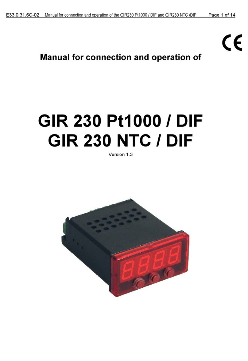
GREISINGER GIR 230 Pt1000 / DIF Instruction manual

GREISINGER
GREISINGER gir 2000Pt Instruction manual

GREISINGER
GREISINGER GIR 300 User manual

GREISINGER
GREISINGER GEWAS 191 User manual

GREISINGER
GREISINGER GIR 230 Pt User manual

GREISINGER
GREISINGER GRA 0420 VO User manual