Grifco LG Drive GGS1000 User manual

Model GGS1000
Chamberlain Australia Pty Ltd
Unit 1, 75 Epping Rd North Ryde NSW 2113
Ph: 1800 GRIFCO
www.grifco.com.au
Ref: 114A5582B
• THIS OPERATOR IS TO BE INSTALLED AND SERVICED BY A TRAINED TECHNICIAN ONLY
• Compatible with Security+ 2.0®accessories
• Compatible with Grifco Battery Backup and myQ Internet Gateway
Slide Gate Opener
(GLD-GO & GLD-GO-LV)
Installation and Operating Instructions
INSTRUCTION MANUAL
Compatible
Reflective
Safety Beam
Compatible
Capable
Visit the LG-Drive landing pages for:
• Product features
• Purchase compatible accessories
• Handy tips & how-to videos
• Digital copy of this manual
• Register your warranty

2
SAFETY INSTRUCTIONS
WARNING!
START BY READING THESE IMPORTANT SAFETY INSTRUCTIONS
ST
About this Manual
These instructions are the original operating instructions according to the AS/NZS 60335.1 in conjunction with AS/NZS 60335.2.103.
The instruction manual must be read carefully to understand important product information. Pay attention to the safety and warning
notices.
Keep the instructions in a safe place and make sure that they can be viewed by the user at all times. Keep the manual for future
reference and to make it available to all persons for inspection, service, maintenance and repair. After installation pass the complete
documentation to the owner.
After installation and programming, all users must be instructed in the function and operation of the gate opener for correct and safe
operation.
Before first use and based on the standard requirements the installer must inspect gates regarding their safe condition.
Before you begin the installation:
This product must be installed by a professional installer.
The installer must understand the following:
• The operation of the drive and potential hazards
• The operation of the manual emergency release mechanism
• The regular maintenance, inspection and care according to the Standards
• The installer must instruct other uses on the safe operation of the gate opener
Please read the operating instructions and especially the precautions. The following symbols are placed in front of instructions to avoid
personal injury or damage to property. Read these instructions carefully.
Warning Symbols
The general warning symbol indicates a danger that can lead to injuries or death. In the text section, the general warning symbols are
used as described below.
DANGER Symbol WARNING Symbol CAUTION Symbol ATTENTION Symbol
Indicates an imminent
hazardous situation which, if not
avoided, will result in death or
serious injury.
Indicates a potentially hazardous
situation which, if not avoided,
could result in death or serious
injury.
Indicates a potentially hazardous
situation which, if not avoided,
could result in minor or
moderate injury.
Indicates practices not
related to personal injury.
Intended Use
The gate opener is exclusively designed and tested for the operation of smooth-running residential gates.
The maximum permissible gate size and the maximum weight must not be exceeded. The gate must open and close smoothly by
hand. Use the opener on gates which comply with the applicable standards and guidelines. Regional conditions of wind loads must
be taken into account when using door or gate panels. Observe the manufacturer’s specifications regarding the combination of gate
and opener. Possible hazards within the meaning of AS/NZS 60335.1 in conjunction with AS/NZS 60335.2.103 are to be avoided
by designing and installing the gate according to the relevant instructions. This gate mechanism must be installed and operated in
accordance with the appropriate safety rules.
Improper Use
The construction of the gate opener is not designed for the operation of heavy-duty gates. It is not permitted on gates that travel with
incline/decline.
Any improper use of the gate opener could increase the risk of accidents. The manufacturer assumes no liability for such usage. With
this gate opener, automated gates must comply with the current, valid local standards, guidelines and regulations, AS/NZS 60335.1 in
conjunction with AS/NZS 60335.2.103.
Only Grifco genuine and approved accessories may be connected to the gate opener. Incorrect installation and/or failure to comply
with the following instructions may result in serious personal injury or damage to property.
DANGER WARNING CAUTION ATTENTION
• Failure to comply with the following instructions may result in serious personal injury or property damage.
• Read and follow all instructions carefully.
• The gate opener is designed and tested to offer safe service, provided it is installed and operated in strict accordance with the
instructions in this manual.

3
SAFETY INSTRUCTIONS
During operation, the gate should not under any circumstances obstruct public path ways and roads (public area). When using tools
and small parts to install or carry out repair work on a gate, exercise caution and do not wear rings, watches or loose clothing.
To avoid serious personal injury due to entrapments, remove any locking device fitted to the gate in order to prevent damage to the
gate.
Installation and wiring must be in compliance with your local building and electrical installation regulations. Power cables must only be
connected to a properly earthed supply.
Disconnect electric power to the system before installation, maintenance, repairs or removing covers. A dual pole isolating switch
must be provided to the mains power supply (permanently-wired installation) to guarantee all-pole disconnection (isolating switch or by
a separate fuse). The repairs and electrical installations may be performed only by an authorized electrician. Emergency Stop Button
must be installed for emergency case based on the risk assessment.
Any possible entrapment caused by the moving gate leaf(s) between gate & walls must be eliminated by respecting the given safety
distances in accordance with the AS/NZS 60335.1 in conjunction with AS/NZS 60335.2.103 and/or with safety devices (e.g. safe
edge).
Testing of the safety function of the drive system is recommended to be carried out at least once a month. Refer also to
manufacturers instruction of the gate system components.
After the installation a final test of the full function of the system and the safety devices must be made.
After installation and commissioning, all users must be instructed in the function and operation of the slide gate opener.
It is important to make sure that the gate always runs smoothly. Gates which stick or jam must be repaired immediately. Employ a
qualified technician to repair the gate, never attempt to repair it yourself. This device is not intended for use by persons (including
children) with restricted physical, sensory or mental abilities or lack of experience or knowledge, unless they are supervised by a
person responsible for their safety or have received instruction in how to use the device. If necessary, control equipment MUST be
mounted within sight of the gate and out of reach of children. Children should be supervised to ensure that they do not play with the
device. Do not allow children to operate push button(s) or remote(s). Misuse of the gate opener system can result in serious injury.

4
CONTENTS
SAFETY INSTRUCTIONS ........................................................................................................................................... 2-3
INTRODUCTION ......................................................................................................................................................... 5-7
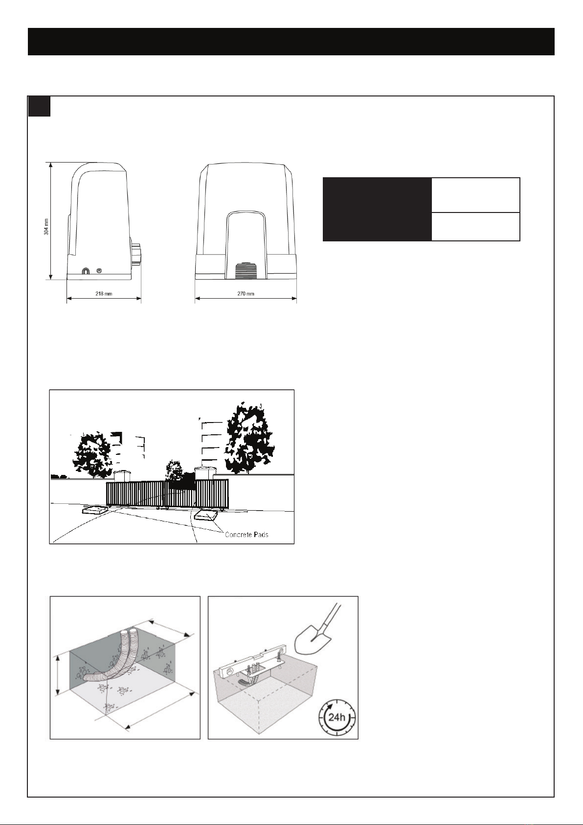
Specifications .........................................................................................................................................................................................5
Sales Kit Inventory..................................................................................................................................................................................5
Tools Needed.........................................................................................................................................................................................6
Overview of Gate Operator.....................................................................................................................................................................6
Planning ........................................................................................................................................................................................... 7-10
INSTALLATION ....................................................................................................................................................... 11-13
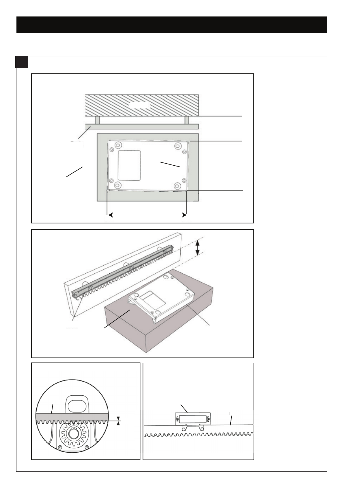
Installing the Base Mounting Plate........................................................................................................................................................11
Disengagement of the Manual Release.................................................................................................................................................11
Installing the Opener on the Base Mounting Plate ................................................................................................................................12
Gate Rack Mounting ............................................................................................................................................................................12
Installing the Limit Switch Brackets ......................................................................................................................................................13
WIRING .................................................................................................................................................................... 14-17
Electrical Safety....................................................................................................................................................................................14
Commissionaing the Gate Opener........................................................................................................................................................14
Access to the Control Board and Motor Connection............................................................................................................................15
Wiring Diagram.....................................................................................................................................................................................16
Install Entrapment Protection Devices ..................................................................................................................................................17
Connect a Battery Backup to the Control Box (Optional)......................................................................................................................17
PROGRAMMING ..................................................................................................................................................... 18-20
LCD Screen Menu................................................................................................................................................................................18
Programming Overview .................................................................................................................................................................. 18-19
Initial Setup...........................................................................................................................................................................................20
BASIC SETTINGS.................................................................................................................................................... 21-26
Limit and Force Learning......................................................................................................................................................................21
Remote Control Behaviour ...................................................................................................................................................................21
IR Behaviour.........................................................................................................................................................................................21
Input Command ...................................................................................................................................................................................22
Pedestrian Command...........................................................................................................................................................................22
Delay Motor 2 in Open and Close Direction.................................................................................................................................... 22-23
Timer To Close (TTC)............................................................................................................................................................................23
Reversal Time.......................................................................................................................................................................................24
E-Lock & Ram Blow Motor 1 for E-Lock ........................................................................................................................................ 24-25
Flashing Light - Pre-Flashing ................................................................................................................................................................25
Special Contact....................................................................................................................................................................................26
Soft & Hard Stop in Open and Close Direction.....................................................................................................................................26
Maintenance Counter ...........................................................................................................................................................................26
ADVANCED SETTINGS .......................................................................................................................................... 27-30
Password .............................................................................................................................................................................................27
Force Motors 1 & 2 Open and Close (Password Protected) .................................................................................................................28
Speed Motors 1 & 2 in Open and Close Direction (Password Protected) .............................................................................................29
Soft-Stop Speed in Open and Close Direction (Password Protected)...................................................................................................29
FACTORY RESET .........................................................................................................................................................30
WIRELESS PROGRAMMING ................................................................................................................................. 31-33
Remote Control Programming..............................................................................................................................................................31
MyQ Set-up.................................................................................................................................................................................... 32-34
OPERATION AND MAINTENANCE ....................................................................................................................... 35-37
Error Codes.................................................................................................................................................................................... 35-36
Accessories and Gate Hardware ..........................................................................................................................................................37
PROGRAMMING FLOW CHART............................................................................................................................ 38-42
CHAMBERLAIN LIMITED WARRANTY ................................................................................................................. 43-44

5
INTRODUCTION
SALES KIT INVENTORY - LG-DRIVE GLD-GO MAINS VOLTAGE 240V OR GLD-GO-LV LOW
VOLTAGE 24V
2
(1) Opener (GLD-GO)
(2) 4 x Slide Gate Rack 1m (MGS-RACK)
(3) Instruction Manual
(4) 2 x Release Keys
(5) 4 x M8x80 Masonry Anchors
(6) 4 x M8x40 Bolts with nuts & washers
(7) Base Mounting Plate
(8) 2 x Premium+ Transmitters (E960G)
(9) 2 x Limit Switch Brackets
(11) Quick Reference Guide
(12) Gate Transformer 240-24V 120VA (MGTR3-120VA)
NOTE: Only for low voltage LG-Drive GLD-GO-LV sales kit.
Your gate opener is packed in separate cartons. The LG-DRIVE GLD-GO or GLD-GO-LV opener sales kit contains the opener, its
hardware, accessories, four metres of rack and a transformer MGTR3-120VA (only for the GLD-GO-LV sales kit).
Main AC Supply:…….…………………...........……….……………..220-240Vac; 50/60Hz
Motor Voltage: …………..…………………..........………………….24 Vdc
Input Power: …………..…………………..........…………………....150 W
Ambient Temperature Range: …………..…………………...........-20 ~ +55˚C
Maximum Weight for single Gate Leaf:…………..……………… 1000 Kg
Maximum Width for single Gate Leaf:…………..………………...12 m
Maximum Pull Force:…………………………….............………….22.5 Nm
Running Time: ................…………..…………………..........………5 minutes
Protection Level: …………..…………………..........……………….IP 44 Suitable for outdoor installation
Maximum Travel Speed .....…………..…………………..........…...31 cm/s
Transmitter Frequency: …………..…………………..........……….433.30 MHz/ 433.92 MHz/ 434.54 MHz
Memory registers:….....................................………………………64 handset codes (max. 4 keypad
devices - 1 code each.)
Dimensions
Gate Opener Height:…………………………….............………….304 mm
Gate Opener Width:………..…………………….............………….270 mm
Gate Opener Depth:…………………………….............…………...218 mm
Gate Opener Weight:…………………………….............………….9 kg
SPECIFICATIONS – LG-DRIVE
1
123
4
5
68
79
Manual
11
10
Quick
Reference
guide

6
INTRODUCTION
OVERVIEW OF THE GATE OPENER
4
Gate
Opener
Limit Switch
Brackets
Limit Switch
Brackets
Gate
Remote
Control
Transformer Box
mounted near
240V power supply
(MGTR3-120VA)
NOTE: Only required
for GLD-GO-LV
l
ow voltage 24V
sales kit
GLD-GO – MAINS VOLTAGE 240V SLIDE GATE OPENER INSTALL OR
GLD-GO-LV – LOW VOLTAGE 24V SLIDE GATE OPENER INSTALL
Gate
Opener
Limit Switch
Brackets
Limit Switch
Brackets
Gate
Remote
Control
Personsare to keep clear! The gate is able to
bemoved without prior warning.
Donot let children operate the gate or play in
thegate area.
Moving Gate Can Cause
Serious Injury Or Death
132A3224-01
WARNING
Warning Label
placed within
the inside of
the post
Transformer Box
mounted near
240V power supply
(MGTR3-120VA)
NOTE: Only required
for GLD-GO-LV
l
ow voltage 24V
sales kit
GLD-GO – MAINS VOLTAGE 240V SLIDE GATE OPENER INSTALL OR
GLD-GO-LV – LOW VOLTAGE 24V SLIDE GATE OPENER INSTALL
Warning Label is provided with each sales kit (GLD-GO & GLD-GO-LV). The warning label must
be placed on the inside of the post.
INSTALLING THE WARNING LABELS
5
Persons are to keep clear! The gate is able to
be moved without prior warning.
Do not let children operate the gate or play in
the gate area.
Moving Gate Can Cause
Serious Injury Or Death
WARNING
132A3224-01
TOOLS NEEDED
3

7
PLANNING
PLANNING
6
Wind Load Rating for Slide Gate Operators
We do not have wind load ratings on our gate openers, as Chamberlain is not responsible for how gate installers design their gates.
Recommendations
• Do not use a solid leaf/panel gate in windy areas.
• Use a light weight picketed slide or swing gate to minimize the wind force.
• Try using a maglock or e-lock to keep the gate securely shut.
• It may be needed to hold the gate(s) open or close, in windy applications.
• When selecting an opener, be sure to select the correct opener for the size of gate.
• You may need to adjust the gate force margins in high wind applications.
Power Wiring
1. The 240V AC opener is supplied with a mains power plug pre-assembled ready for installation. This may require mains power
supply to be provided close to the opener by a licensed electrician.
2. The 24V AC opener will require a low-voltage power supply from the transformer box (MGTR3-120VA to the gate opener.
3. The recommended cable sizes for the connection between the transformer box and the Low Voltage (LV) openers:
• Flexible 3 core cable:
• Less than 20m, minimum 1.5mm²
• 20m to 50m, minimum 2.5mm²
• 50m to 100m, minimum 4mm²
4. It is recommended that the Low Voltage (LV) power cable is run inside conduit to the opener as per local installation requirements.
Suitable cable glands must be used that provide sufficient cable restraint against a minimum of 30 N pull force.
Earthing Recommendations
Proper earthing of the operator is recommended to improve the radio range of transmitters and wireless accessories.
• The 240V AC unit is earthed using the standard AC power plug provided
• For the Low Voltage unit earthing can be achieved by running an earth wire back to the transformer box
• Alternatively connect the earth wire supplied with the LV unit to a suitable earth point on the operator base plate
• The use of an extension antenna kit SWG-ANT-EV may also be used to improve the radio range.
Additional Accessories
The vehicle loops allow the gate to stay open when vehicles are obstructing the gate path. Suggested for vehicles 4.2m or longer.
Vehicle loops are not required but are recommended. Before installing any accessories be sure to complete a site check to determine
the best device(s) the site needs.
Before installing the gate opener, ensure that the gate is opening smoothly. Ensure that all the required cables
(power cable, accessory cables etc) are prepared and laid correctly.
NOTE: All crushing points must be secured by an entrapment protection according to AS/NZS 60335.1 in conjunction with
AS/NZS 60335.2.103.

8
PLANNING
PLANNING CONTINUED
6
GATE OPENER
Maximum Gate Weight 1000kg
Maximum Gate Width 12m
Conduit and Concrete Pad
Trench and install conduit. Before trenching, contact underground utility authorities. Conduit must be approved for low and mains
voltage. Consider the opener placement BEFORE installing the pad or post.

9
INTRODUCTION
PLANNING CONTINUED
6
Safety Catch Rollers
Install catch rollers with safety covers on the side of a post or wall with a minimal distance of approximately 1.2cm between
the rollers and gate.
Safety
Safety entrapment protection devices are recommended to protect against any entrapment or safety conditions encountered in your
gate application. Install the two warning signs provided on the inside and outside of the property, where easily visible.

10
INTRODUCTION
Underneath the
mounting plate
is the concrete
slab
Mounting
plate
Rack
270 mm
170 mm 60 mm
Underneath the
mounting plate
is the concrete
slab
one of the two
limit switch brackets
Mounting
plate
Rack
Rack
90 - 100mm
R
ack
Rac
k
Gate
Rack
2-3mm
PLANNING CONTINUED
6
Base Mounting Plate Position
Base Mounting Plate
Rack Limit Switch Brackets

11
INSTALLATION
DISENGAGEMENT OF THE MANUAL RELEASE
8
1. Remove the small front plastic cover from the operator.
2. Put the key into keyhole and turn right.
3. Pull the lever down.
NOTE: To re-engage the opener follow the procedure in reverse.
INSTALLING THE BASE MOUNTING PLATE
7
Underneath the
mounting plate
is the concrete
slab
Mounting
plate
90 - 100mm
Rack
1. Position the base mounting plate as required, referring to the planning section (figure 1).
2. Mark and drill the four masonry anchor holes (figure 2).
NOTE: Position the power cord through the base mounting plate before mounting the base plate.
3. Mount the base mounting plate to the ground or concrete pad using the four masonry anchors provided.
NOTE: Ensure the base mounting plate is orientated in the correct way. The arrow on the base mounting plate needs to be set
towards the gate.
figure 1 figure 2

12
INSTALLATION
1. Remove the screws from the side of the housing (figure 1) and remove the cover.
2. Once the base mounting plate is fixed, position the gate opener onto the base mounting plate ensuring that it is correctly to the
gate and the rack. See planning section for more details.
3. Using the fasteners provided, secure the gate opener to the base mounting plate.
NOTE: If the rack is already fixed to gate, it may be required to adjust the height of the gate opener to ensure correct
engagement of the drive gear with the gate rack.
figure 1 figure 2
1. Manually move the gate into OPEN position.
2. The nylon rack can be attached with screws. Put the first rack segment at the end of the gate so that it rests on the opener drive
sprocket (figure 1) and attach the rack to the gate (figure 2).
3. Move the gate and attach the next rack segment near to the previous segment. Proceed this way until you will reach complete
CLOSED position.
NOTE: If the rack is already fixed to gate, it may be required to adjust the height of the gate opener to ensure correct
engagement of the drive gear with the gate rack.
figure 1 figure 2
GATE RACK MOUNTING
10
INSTALLING THE OPENER ON THE BASE MOUNTING PLATE
9

13
INSTALLATION
1. Position the limit switch brackets in the approximate open and close positions on the rack. Loosely attach the brackets to the rack.
The magnets are marked "L" and "R". L positioned on the left of the rack, while R is positioned on the right of the rack when
looking from inside the property. When attaching the brackets, ensure that the magnets are 12mm to 20mm from the limit switch
sensor on the opener.
2. Place the housing cover over the opener and move the gate manually to the open and close positions to ensure that the limit
switch brackets do not come into contact with the gate structures or the gate opener. Position the magnets so that they will align
with the sensor mounted on the opener when the gate is approximately 10mm from the OPEN or CLOSED position. This will allow
for the Basic Setup to be completed without the gate hitting the stops too hard.
NOTE: After Basic Setup, fine tuning of the Limit Switch Mounting Brackets to allow the gate to open and close fully.
INSTALLING THE LIMIT SWITCH BRACKETS
11
figure 2
figure 1 figure 3
figure 4

14
WIRING
For 240V AC opener, plug the opener into mains power. Alternatively if the gate is to be hard-wired into 240V power, this must be
completed by a licensed electrician. Now go to programming section.
For 24V (Low Voltage) opener, connect the low-voltage power cord from the opener to the low-voltage power supply from the
transformer box MGTR3-120VA. Proceed to programming section.
COMMISSIONING THE GATE OPENER
13
ELECTRICAL SAFETY
12
To reduce the risk of SEVERE INJURY or DEATH:
• BEFORE installing the power wiring or control stations be sure to follow all specifications and warnings. Failure to do so
may result in SEVERE INJURY to persons and/or damage to the opener.
• ALL electrical connections MUST be made by a licensed electrician.
• DO NOT install any wiring or attempt to run the opener without consulting the wiring diagram.
• ALL power wiring should be on a dedicated circuit and well protected.
• ALL power and control wiring MUST be run in separate conduit.
• Disconnect power at the fuse box BEFORE proceeding.
• ANY maintenance to the opener or in the area near the opener MUST NOT be performed until disconnecting the electrical
power (AC and battery). Upon completion of maintenance the area MUST be cleared and secured, at that time the
unit may be returned to service.

15
WIRING
The control board Is already pre-installed and pre-wired to the motor terminal. No extra action Is required. To gain access to the control
board remove the opener cover. The terminals for wiring accessories are directly accessible. To get access to the programming
buttons remove the transparent plastic cover and place it back once programming is finalised.
ACCESS TO THE CONTROL BOARD AND MOTOR CONNECTION
14
figure 2
figure 1
figure 3

16
WIRING
WIRING DIAGRAM
15
12
10
13
55
5
5
9
10
12
10
0
0
0
0
4321
1
2
3
3 12
1
2
12
13
14
4
11
10
9
8
7
6
5
1
3
2
34 2 1
3
2
1
2 13
2 13
2
1
2
1
1
2
1
22
1
2
11
2
1
2
5
432
1
678910
2
1
11
1
2
11
1
1
Dual driver primary secondary SYNC
IN1
IN1
IN2
IN2
IN3
IN3

17
WIRING
24 V BAT
POW
24 V
POWER BOARD
THE PROTECTOR SYSTEM™ (IR BEAMS) (OPTIONAL)
NOTE: Grifco strongly recommends that The Protector System™ (IR Beams) be installed on all gate openers.
Compatible Protector System™ (IR Beams) are 772ANZ and GPS15 Monitored Safety Beams.
The Protector System™ (IR Beams) can be configured to function differently when connected to IR1, IR2 or IR3 inputs.
1. Connect the Protector System™ (IR Beams) to IR1/GND or IR2/GND and or IR3/GND.
2. The IR Beams can be configured to monitor in the open or close direction or both (see section 23 IR Behaviour).
3. The IR Beams will automatically learn to the opener after they have been connected and are default to monitor the close direction.
4. If you need to remove the IRs, you will need to unlearn them from the opener. This is done by switching off the mains power off and
on again twice.
INSTALL ENTRAPMENT PROTECTION DEVICES
16
EDGE SENSOR
The Edge sensor can only be connected to the Edge inputs.
1. Remove the 8.2k resistor from the Edge inputs.
2. Connect the 8.2k compatible edge sensor to the Edge inputs.
EDGE
SE SE
IR SENSOR
GND IR3 IR2 IR1
COMMAND
GND IN3 IN2 IN1
FLA E-LK SPEC
EDGE
SE SE
IR SENSOR
GND IR3 IR2 IR1
COMMAND
GND IN3 IN2 IN1
FLA E-LK SPEC
BATTERY BACKUP (OPTIONAL)
17
The batteries are charged in the circuit by the integrated transformer. Recommended items for a battery backup application (separate
accessory purchase) 2 x 12V 2.2Ah SLA batteries (model MGBBU).
1. Disconnect AC power to the opener.
2. Insert the battery power wires through the same hole as the AC power wires.
3. Connect the battery cable to the BATTERY terminals on the power board.
4. Place the batteries inside the opener.
5. Connect a jumper with an in-line fuse (10A) between the positive (+) terminal on one battery and the negative (-) terminal on the
other battery.
6. Connect the positive battery cable wire to the positive (+) terminal on the PCB.
7. Connect the negative battery cable wires to the negative (-) terminal on the other PCB.
8. Reconnect AC power to the opener.
9. Place cover on the opener.

18
PROGRAMMING
Programming buttons function (4 buttons):
LCD SCREEN MENU
18
Button Function
SProgram / delete remote controls and
specific functions
P
Enter programming mode, select
function and save.
NOTE long press of P button will save
the setting and exit out to the menu
screen.
+/- Navigate through the menu and change
the value on display
The programming of the boards is divided in two steps:
1. Basic - including Initial Setup
2. Advanced - Password Protected Settings
Initial Set-up includes:
• Selection of motor type
• Motor direction
• Limits
• Forces.
After the Initial Set-up is complete, the opener will work as per default Basic Settings.
Initial Set-up is mandatory, if they are not completed, the opener will not work.
Initial Set-up is required before any further changes to Basic or Advanced settings can be made
OVERVIEW
19

19
PROGRAMMING
OVERVIEW
19
Legend Function Section
Application Opener Motor Type 20
Direction Motor 1 Direction Motor 1 20
Direction Motor 2 Direction Motor 2 20
Limit & Force Learn Learning 21
Remote Control Behaviour Adjust the behaviour of remote controls 22
IR1-Behaviour Adjust the behaviour of Protector System Safety IR Beams in input IR 1 23
IR2-Behaviour Adjust the behaviour of Protector System Safety IR Beams in input IR 2 23
IR3-Behaviour Adjust the behaviour of Protector System Safety IR Beams in input IR 3 23
Input 1 Adjust the behaviour of Input 1 command 24
Input 2 Adjust the behaviour of Input 2 command 24
Input 3 Adjust the behaviour of Input 3 command 24
Pedestrian Setup pedestrian opening mode 25
Delay Motor 2-Open Adjust timing delay of motor 2 in open direction 26
Delay Motor 1-Close Adjust timing delay of motor 1 in close direction 27
Timer-To-Close Setup timer-to-close feature 28
Reversal Time Reversal time after obstruction has been detected 29
E-Lock E-Lock 30
Ram-Blow Setup additional electronic lock (E-Lock) or Mag-Lock options 31
Flashing Light Setup flashing light accessory 32
Pre Flashing Adjust pre flashing of flashing light accessory 33
Special Contact Relay Adjust how the special contact input will behave 34
Soft & Hard Start Setting Disable or enable the soft & hard starts 35
Maintenance Counter Setup maintenance counter for service alerts 36
The above completes the Basic Setting requirements
Password Setup, enter and change password in order to enter into the Advance settings 37
Force Motor 1-Open (PW) Adjust the forces of motor 1 in open direction 38
Force Motor 1-Close (PW) Adjust the forces of motor 1 in close direction 38
Force Motor 2-Open (PW) Adjust the forces of motor 1 in open direction 38
Force Motor 2-Close (PW) Adjust the forces of motor 2 in close direction 38
Speed-Motor 1 & 2 Open (PW) Adjust the speed of motor 1 and 2 in open direction 39
Speed-Motor 1 & 2 Close (PW) Adjust the speed of motor 1 and 2 in close direction 40
Soft Stop Speed (PW) Adjust the soft speed, which is the remaining speed towards the end of the travel 41
Factory Reset Reset opener 42
Finish and Exit Complete and exit screen N/A

20
PROGRAMMING
INITIAL SETUP
20
Energise the opener. Release the opener manual release
with the key, and move the gate(s) to a mid open position.
Re-engage the manual release.
The LCD screen will display the Cycle count.
1. Press and hold the “P” button for approximately 5
seconds to enter into the Main Menu. MAIN MENU
SELECT APPLICATION will be displayed on the LCD.
2. Press the “P” button once to enter this Menu option.
3. Use the “+” or “-” to scroll though the motor
application options. When “SLIDER GGS1000” is
shown, press the “P” button to select. The screen will
change to show MAIN MENU SELECT APPLICATION.
4. Press the “+” button once to scroll to the next menu
option. “MAIN MENU DIRECTION MOTOR1” will be
displayed on the LCD.
5. Press the “P” button to select. The screen will change
to show PRESS & HOLD “+” GATE OPENING? YES
“P”, NO “S”.
6. Press and hold “+”. The gate will start to move.
a) If it moves in the OPEN direction, press “P” to
confirm”. The screen will change to show MAIN
MENU DIRECTION MOTOR!
b) If the gate moves in the CLOSE direction, press
“S” to confirm. The screen will change to
EXECUTE MOTOR DIRECTION CHANGE.
Press “P” to confirm.
Once the direction has been confirmed, the
screen will change to MAIN MENU DIRECTION
MOTOR. If there is a second slide gate opener to
be setup, press the ”+” button to scroll to the
next menu option “MAIN MENU DIRECTION
MOTOR2 and follow the steps 5 and 6.
7. Press the “+” button once to scroll to the next menu
option. “MAIN MENU LIMIT&FORCE LEARN” will be
displayed on the LCD.
8. Press the “P” button to select.
The gate will start to
move.
The screen will change and LIMIT&FORCE
LEARN will flash on the screen.
9. Once complete, the gate will stop moving and the
screen will change to CYCLES: 000,000 STANDBY
GATE CLOSED.
Initial setup is now complete. The opener will now operate
using default Basic Settings.
NOTE: If the LIMIT&FORCE LEARN setup needs to be
stopped, press the “S” button. The Screen will
display LIMIT&FORCE LEARN INTERRUPTED. After 5
seconds, the screen will display LIMIT&FORCE
LEARN. Repeat step 8 to complete basic setup.
-
SP
+-
SLIDER
GGS1000
SP
+-
SP
+-
MAIN MENU
DIRECTION MOTOR1
PRESS & HOLD “+”
GATE OPENING?
YES “P”, NO “S”
SP
+-
MAIN MENU
DIRECTION MOTOR1
SP
+-
MAIN MENU
SELECT
APPLCATION
SP
+-
CYCLES: 000, 000
BEGIN SETUP
SP
+-
MAIN MENU
SELECT
APPLCATION
SP
+-
MAIN MENU
SELECT
APPLCATION
SP
+-
MAIN MENU
LIMITED & FORCE
LEARN
SP
+-
MAIN MENU
SELECT
APPLCATION
SP
+-
MAIN MENU
LIMITED & FORCE
LEARN
SP
+-
CYCLES 000,000
STANDBY
GATE CLOSED
figure 1
figure 2
figure 3
This manual suits for next models
2
Table of contents
Other Grifco Gate Opener manuals