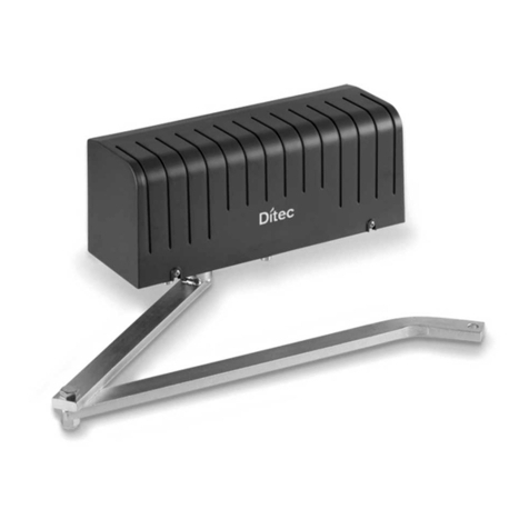
DITEC DAB305 Manual

Swing Door Operator
Ditec DAB305
Installation and Service Manual
Original instructions
1020527-DIen-3.0 –Issue 2021-06-07

© All rights in and to this material are the sole property of ASSA ABLOY Entrance Systems AB. Copying, scanning, alterations or
modifications are expressly forbidden without the prior written consent of ASSA ABLOY Entrance Systems AB. Rights reserved for
changes without prior notice.
Backtrack information: folder:Workspace Main, version:a667, Date:2021-06-07 time:05:33:25, state: Frozen

CONTENTS - Original instructions
71 Revision .....................................................................................................................................................................................
82 Instructions for safe operation ...........................................................................................................................................
93 Important information .........................................................................................................................................................
93.1 Intended use ....................................................................................................................................................................................
93.2 Safety precautions .........................................................................................................................................................................
93.3 Electronic equipment reception interference .....................................................................................................................
103.4 Environmental requirements .....................................................................................................................................................
114 Technical specifications ........................................................................................................................................................
124.1 Permitted door weight and door width for Ditec DAB305 ..............................................................................................
135 How the Ditec DAB305 works ............................................................................................................................................
145.1 Opening ............................................................................................................................................................................................
145.2 Closing ...............................................................................................................................................................................................
145.3 Control switch .................................................................................................................................................................................
145.3.1 OFF/AUTO/OPEN switch ..............................................................................................................................................
145.4 Functions on the basic control unit CUS7 (DAB305CU) ...................................................................................................
145.4.1 Power failure ..................................................................................................................................................................
145.4.2 Closing torque ...............................................................................................................................................................
155.4.3 Extended closing torque (CLTQ) .............................................................................................................................
155.4.4 Power assist (POAS) .....................................................................................................................................................
155.4.5 Push and go (PAG) ........................................................................................................................................................
155.4.6 Inverse (INV) ..................................................................................................................................................................
155.4.7 Activation delay (AD) ..................................................................................................................................................
155.4.8 Overhead presence detector (OPD), frame mounted .....................................................................................
155.4.9 Mat ....................................................................................................................................................................................
165.4.10 Double acting ................................................................................................................................................................
165.5 Functions on the extension unit DAB905ESE .......................................................................................................................
165.5.1 KILL or FIRE function ....................................................................................................................................................
165.5.2 Function of locks ...........................................................................................................................................................
165.5.3 Program selector (wall mounted) ..........................................................................................................................
165.5.4 Impulses ..........................................................................................................................................................................
175.5.5 OPEN/CLOSE impulse ..................................................................................................................................................
175.5.6 Power failure mode (backup batteries are installed) –optional ..................................................................
185.5.7 Nurse and bed functionality .....................................................................................................................................
185.6 Functions on the extension unit DAB905ESA .......................................................................................................................
185.6.1 Presence impulse approach, door mounted .......................................................................................................
195.6.2 Presence detection swingpath, door mounted ..................................................................................................
195.6.3 Monitored safety sensors ...........................................................................................................................................
195.6.4 FIRE input ........................................................................................................................................................................
195.6.5 Relay output ...................................................................................................................................................................
206 Models ........................................................................................................................................................................................
206.1 Single operator, surface mounted ............................................................................................................................................
216.2 Double operator, surface mounted .........................................................................................................................................
227 Part identification ...................................................................................................................................................................
248 Arm systems .............................................................................................................................................................................
248.1 Pushing installation with PUSH-arm .......................................................................................................................................
258.2 Pulling installation with PULL-arm ...........................................................................................................................................
258.3 20 mm extension ...........................................................................................................................................................................
268.4 Pushing installation with PULL-arm ........................................................................................................................................
278.5 Drive shaft extension kits ............................................................................................................................................................
289 Options ......................................................................................................................................................................................
289.1 Control switches ............................................................................................................................................................................
289.1.1 4-position switch COM400MHB/MKB (operates the electric lock) .............................................................
289.2 Sync cable for double doors (synchronizing of 2 operators) ..........................................................................................
289.3 Coordination unit .........................................................................................................................................................................
299.4 LED Cable ..........................................................................................................................................................................................
3Issue 2021-06-071020527-DIen-3.0

299.5 Battery backup unit .......................................................................................................................................................................
299.6 Cover piece kit ................................................................................................................................................................................
299.7 Closing time board kit .................................................................................................................................................................
309.8 Fire kit ...............................................................................................................................................................................................
309.9 Labels .................................................................................................................................................................................................
3110 Pre-installation ........................................................................................................................................................................
3110.1 General tips/Safety concerns .....................................................................................................................................................
3110.2 Operator/Door handing ...............................................................................................................................................................
3210.3 Installation examples ....................................................................................................................................................................
3210.4 Fastening requirements (but not included) .........................................................................................................................
3310.5 Tools required .................................................................................................................................................................................
3411 Mechanical installation ........................................................................................................................................................
3711.1 PUSH arm system ...........................................................................................................................................................................
4311.2 PULL arm system ............................................................................................................................................................................
4911.3 Operator with sliding PUSH arm system ................................................................................................................................
5011.4 Inverse installation with PUSH arm system ..........................................................................................................................
5111.5 Inverse installation with PULL arm system ...........................................................................................................................
5211.6 Installation of coordination unit on Fire Door installations ............................................................................................
5812 Electrical connection .............................................................................................................................................................
5912.1 Control units ....................................................................................................................................................................................
5912.1.1 CUS7 (DAB305CU) .......................................................................................................................................................
5912.1.2 Arm system selection ..................................................................................................................................................
6012.1.3 Extension units DAB905ESE / DAB905ESA ............................................................................................................
6112.1.4 Extension unit DAB905ESE ........................................................................................................................................
6212.1.5 Extension unit DAB905ESA ........................................................................................................................................
6312.1.6 Installation on double doors ....................................................................................................................................
6312.2 How to cut the jumper on the sync cable for double doors ...........................................................................................
6412.3 Double door installations ...........................................................................................................................................................
6412.4 Settings for double doors ............................................................................................................................................................
6512.5 Sensor cable inlet ...........................................................................................................................................................................
6612.6 Reset and indication device for Fire Doors ............................................................................................................................
6813 Start-up ......................................................................................................................................................................................
6813.1 Spring pre-tension .........................................................................................................................................................................
6913.2 Micro switch ...................................................................................................................................................................................
6913.3 Adjusting the door stop ...............................................................................................................................................................
7113.4 Auto-learn-automatically sets back and latch check (recommended) .......................................................................
7213.4.1 Push the LEARN BUTTON (LRN) ...............................................................................................................................
7213.4.2 Double doors .................................................................................................................................................................
7213.5 General adjustment ......................................................................................................................................................................
7313.6 Connection of activation units and accessories ..................................................................................................................
7414 Cover ..........................................................................................................................................................................................
7414.1 Fitting and removing the cover .................................................................................................................................................
7414.2 Cover piece kit ................................................................................................................................................................................
7515 Signage .......................................................................................................................................................................................
7616 Advanced settings ..................................................................................................................................................................
7616.1 Learn with advanced setting of “back- and latch-check”..................................................................................................
7616.2 Revert to default values for “back- and latch-check" (Level 1) .......................................................................................
7716.3 Changing group of parameters (Level 2) ...............................................................................................................................
8016.4 Classification (Level 3) .................................................................................................................................................................
8116.5 Overhead Presence Detection and Interlock (Level 4) .....................................................................................................
8216.6 Enhanced Lock Kick, Fire Input and Extended Arm Selection (Level 5) .......................................................................
8317 Guide for installation and adjustments ..........................................................................................................................
8317.1 Complementary Safety Devices Swing Doors ......................................................................................................................
8317.2 Swing Doors Opening and Closing Time ................................................................................................................................
8317.2.1 How to find the correct opening and closing time ...........................................................................................
8417.3 Diagrams for Door weight ..........................................................................................................................................................
8417.3.1 Aluminium frame with glass .....................................................................................................................................
1020527-DIen-3.0Issue 2021-06-074
8518 Troubleshooting .....................................................................................................................................................................
8618.1 Error indication ...............................................................................................................................................................................
8719 Service/Maintenance .............................................................................................................................................................
5Issue 2021-06-071020527-DIen-3.0

1020527-DIen-3.0Issue 2021-06-076

2 Instructions for safe operation
•Failure to observe the information in this manual may result in
personal injury or damage to equipment.
•To reduce the risk of injury to persons - use this operator with single
or double pedestrian swinging or folding doors only.
•Do not use the equipment if repair or adjustment is necessary.
•Disconnect supply when cleaning or other maintenance is to be
carried out.
•The operator can be used by children over 8 years of age if they have
been instructed by a person in charge of their safety.
•The operator can be used by children 8 years of age or younger if
they are supervised by a person responsible for their safety.
•The operator can be used by persons with impaired physical, sensory
or mental capacity if they have been instructed by a person in charge
of their safety.
•Cleaning and user maintenance shall not be made by children.
•Do not let anyone climb on or play with the door or the fixed/remote
controls.
•Risk of battery explosion if wrong type of battery is used.
•The door has no safety during auto-learn cycle. Remain clear of
swing path of door, as door may close rapidly.
•In all instances, where work is being done, the area is to be secured
from pedestrian traffic, and the power removed to prevent injury.
•In the event that the KILL circuit is activated, all Safety Functions of
the door will be overridden causing the door to close even though
an object or person may be in the door's path of travel, and therefore
may be subject to injury. This mode of operation is most generally
used to isolate an area in the event of a fire.
•The doorset can be operated automatically by sensors or manually
by activators. It can also be used manually as a door closer.
1020527-DIen-3.0Issue 2021-06-078
2 Instructions for safe operation

3 Important information
3.1 Intended use
The Ditec DAB305 is an automatic swing door operator developed to facilitate entrances to
buildings and within buildings through swing doors. The Ditec DAB305 is an electromechanical
operator approved for fire door applications. It is to be installed indoors where it is suitable for al-
most all types of external and internal swing doors. This widely-used operator can be found in ap-
plications ranging from handicapped-access in private homes to high-traffic retail operations.
Door operator used in escape routes shall be installed so that the door opens in the escape direction
unless the system allows break-out in this direction.
The motor and gear box are combined into a compact unit mounted alongside the control unit
within the cover. The operator is connected to the door leaf with a range of different arm systems.
The door is designed to offer continuous use, a high degree of safety and maximum lifetime. The
system is self-adjusting to the effects caused by normal variations in the weather conditions and
to minor friction changes caused by e.g. dust and dirt.
For escape in emergency situations the doorset is opened manually.
This manual contains the necessary details and instructions for the installation, maintenance and
service of the Swing Door Operator Ditec DAB305.
For use see User manual 1020517.
Save these instructions for future reference.
3.2 Safety precautions
Be sure to complete a risk assessment and site acceptance test before taking the door into operation.
To avoid bodily injury, material damage and malfunction of the product, the instructions contained
in this manual must be strictly observed during installation, adjustment, repairs and service etc.
Training is needed to carry out these tasks safely. Only Ditec-trained technicians should be allowed
to carry out these operations.
3.3 Electronic equipment reception interference
The equipment may generate and use radio frequency energy and if not installed and used properly,
it may cause interference to radio, television reception or other radio frequency type systems.
If other equipment does not fully comply with immunity requirements, interference may occur.
There is no guarantee that interference will not occur in a particular installation. If this equipment
does cause interference to radio or television reception, which can be determined by turning the
equipment off and on, the user is encouraged to try to correct the interference by one or more of
the following measures:
•Re-orient the receiving antenna.
•Relocate the receiver with respect to the equipment.
•Move the receiver away from the equipment.
•Plug the receiver into a different outlet so that equipment and receiver are on different branch
circuits.
•Check that protective earth (PE) is connected.
If necessary, the user should consult the dealer or an experienced electronics technician for addi-
tional suggestions.
9Issue 2021-06-071020527-DIen-3.0
3 Important information

3.4 Environmental requirements
Ditec products are equipped with electronics and may also be equipped with batteries containing
materials which are hazardous to the environment. Disconnect power before removing electronics
and battery and make sure it is disposed of properly according to local regulations (how and where)
as was done with the packaging material.
1020527-DIen-3.0Issue 2021-06-0710
3 Important information

4 Technical specifications
Ensure that the door operator with technical specification below is suitable for the installation.
ASSA ABLOY Entrance Systems ABManufacturer:
Lodjursgatan 10, SE-261 44 Landskrona, SwedenAddress:
Ditec DAB305Type:
100-240 V AC +10/-15%, 50/60 Hz, mains fuse max 10A (building
installation)
Mains supply:
Note! The mains supply shall be installed with protection and an
all-pole mains switch with isolating capability of Category III, at least
3 mm between contacts, shall be installed according to local regu-
lations. These articles are not provided with the door.
Max. 300 WPower consumption:
24 V DC, max. 700 mA (max. 1000 mA including lock)Auxiliary voltage:
2 x T 6,3 AH/250 VMains fuse F1, F2:
PUSH arm system; size 4 - 7Door size:
PULL arm system; size 4 - 6
For PUSH = 140 kgm2
For PULL = 80 kgm2
Inertia = Door weight x (Door width)2/ 3
Selectable: 12 V DC, max. 1200 mA or 24 V DC, max. 600 mAElectro-mechanical locking
device:
PUSH arm: 80° - 110, with reveal 0 - 367 mmDoor opening angle:
PULL arm and Sliding PUSH arm: 80° - 110, with reveal -20 - 130 mm
Variable between 2.5 - 12 sOpening time (0° - 80°):
Variable between 4 - 12 sClosing time (90° - 10°):
1.5 - 30 sHOLD open time:
-20 °C to +45 °CAmbient temperature:
Max. 95%Relative humidity:
7.6 kgDrive unit weight:
IP20Class of protection:
IP54Degree of protection, con-
trol actuators:
Third party approvals from established certification organizations
valid for safety in use, see Declaration of Incorporation.
Approvals:
Complies with: EN 16005, EN 60335-2-103, EN 1634-1
11Issue 2021-06-071020527-DIen-3.0
4 Technical specifications

This product is to be installed internally.
3716.5
175
70
70
16.5
4.1 Permitted door weight and door width for Ditec DAB305
PUSH arm
PULL arm
0
50
100
150
200
250
300
350
400
450
0.8 0.9 1 1.1 1.2 1.3 1.4
PUSH arm
PULL arm
J=140 kgm²
J=80 kgm²
PUSH arm
PULL arm
Door weight (kg)
Door width (m)
1020527-DIen-3.0Issue 2021-06-0712
4 Technical specifications

5 How the Ditec DAB305 works
The swing door operator Ditec DAB305 uses a DC motor which is connected to the output shaft
by a combination of a worm gear and spur gears. The push- or pull arm system that is connected
to the output shaft opens the door in a surface mounted application.
There is an adjustable spring mechanism, consisting of a helical compression spring combined
with a linkage system including a pressure roller that acts on a cam curve that is attached to the
output shaft. During opening of the door, the compression spring is tensioned by the rotation of
the output shaft. During the closing cycle, the accumulated spring force is transferred to the output
shaft by means of the cam curve and the pressure roller. The transferred spring force is acting in
the closing direction.
The spring force can be adjusted so that there is appropriate force to close the door when it is
manually operated or if there is a power failure.
It is possible to increase the closing force by using the motor in combination with the spring and
thereby increase the door closing force (powered close).
The mechanism consist of:
1
6
4
2
3
5
7
8
9
10
11
Motor1
Worm gear2
Two spur gears3
Output shaft4
Helical compression spring5
Spring mechanism that transfer the spring force to the output shaft6
Cam to optimise the torque on the output shaft7
Mechanical door stop on the output shaft (adjustable)8
Shaft for a mechanical coordinator9
Encoder10
Micro switch11
13Issue 2021-06-071020527-DIen-3.0
5 How the Ditec DAB305 works

5.1 Opening
When an activation signal is received by the control unit, the door is opened at the installer-adjusted
opening speed. Before the door is fully open at back check, it slows automatically to low speed.
The motor stops when the selected door opening angle has been reached. The open position is
held by the motor.
If the door is obstructed while opening, it will either stall or stop which can be selected with a DIP-
switch (SOS). Stop on stall is always active in program selector Mode Off.
•Continue on stall - the door will continue to try to open during the hold open time.
•Stop on stall - the door will, even if hold open time has not expired, close after 2 seconds.
5.2 Closing
When the hold open time has elapsed, the operator will close the door automatically, using spring
force and motor. The door will slow to low speed at latch check before it reaches the fully closed
position. The door is kept closed by spring power or combined with extended closing torque by
the motor.
5.3 Control switch
5.3.1 OFF/AUTO/OPEN switch
FUNCTION
OFF
AUTO OPEN
White Brown
Green
ProgramFunction
Key is the only valid impulse.OFF
Every impulses are valid.AUTO
The door is held permanently open.OPEN
5.4 Functions on the basic control unit CUS7 (DAB305CU)
See page 59 for more information.
5.4.1 Power failure
During power failure the operator acts as a door closer with controlled closing speed and a micro
switch will make a lock kick to secure latching (only fire rated version and no Inverse installation).
5.4.2 Closing torque
To comply with authority requirements or to overcome over/under pressure the closing torque
can be adjusted according to EN1154.
1020527-DIen-3.0Issue 2021-06-0714
5 How the Ditec DAB305 works

5.4.3 Extended closing torque (CLTQ)
If the potentiometer CLTQ is set to 0°, the door will close with normal spring power. If the poten-
tiometer is turned clockwise, the motor will increase the closing torque. Extended closing torque
will be reduced to zero:
•If the door mounted sensor is activated in closed position or during closing (even if manually
opened). Applies not to program select OFF.
Also, Extended closing torque will be canceled after the first closing by KILL, in all program se-
lections (except secondary door with older firmware).
5.4.4 Power assist (POAS)
If the potentiometer POAS is set to 0°, the door gives no power assist. If the potentiometer is turned
clockwise, the motor will give/increase power assist when the door is opened manually. The range
of the POAS is depending on the spring pre-tension.
5.4.5 Push and go (PAG)
DIP-switch to select Push and Go, ON or OFF. Push and Go is available from any door position. Push
and Go is not active in programme selector setting OFF.
5.4.6 Inverse (INV)
DIP-switch to select when inverse installation.
To be used for doors in emergency escape routs where the door has to open in case of fire alarm
(smoke evacuation). The door is opened by spring force and closed by motor operation. If lock is
used, the lock must fulfill the ELtVTR-standard.
5.4.7 Activation delay (AD)
This function requires a constant inner impulse for the specified time before the door will open.
Fixed 2 sec.
During closing the door will reopen immediately if impulsed.
5.4.8 Overhead presence detector (OPD), frame mounted
When an OPD sensor is mounted on the frame or operator cover just above the swing side of the
door, it will–when activated–either keep the door open or closed. The sensor input is not sensative
during opening and closing. Lock-out signal is available as it is required by some OPD sensors for
proper function.
•a closed door will not open, if the OPD detects activity in the field
•an open door will not close, if the OPD detects activity in the field
•during opening, the door will continue to open, even if the OPD detects activity in the field
•during closing, the door will continue to close, even if the OPD detects activity in the field
•the OPD is not active in program mode OFF, manually opened door or during battery operation
(Power Save Mode).
5.4.9 Mat
Mat safety means that:
•a closed door will not open, if someone steps on the mat
•an open door will not close, if someone steps on the mat
•during opening, the door will continue to open, even if someone steps on the mat
•during closing, the door will continue to close, even if someone steps on the mat
•opening impulses are prevented during closing, if someone steps on the mat
•the mat is not active in program mode OFF, manually opened door or during battery operation
(Power Save Mode).
15Issue 2021-06-071020527-DIen-3.0
5 How the Ditec DAB305 works

5.4.10 Double acting
Opening inwards and with panic break out outwards
5.5 Functions on the extension unit DAB905ESE
Also see page 61 for more information.
5.5.1 KILL or FIRE function
In the event that the KILL or FIRE circuit is activated, all Safety Functions of the
door will be overridden causing the door to close even though an object or
person may be in the door's path of travel, and therefore may be subject to injury.
This mode of operation is most generally used to isolate an area in the event
of a fire. In double doors, coordinator shall be used to ensure correct closing.
•During KILL the control will ignore all signals and close door(s) at normal speed or 5 seconds
(see page 72).
•If impulse controlled KILL or FIRE: The operator will resume normal operation after a KILL RESET.
When manual RESET, jumper must be removed and reset button connected to terminal No. 8
and Ground.
•Or if state controlled KILL When KILL signal is no longer active, operator will resume normal
operation.
•The behavior of the lock during KILL depends on the group of parameters. See page 77.
•Green LED indicates trouble-free operation of the operator. No triggering of the connected
devices (smoke detector or manual release button).
•Red LED indicates the release of one or more triggering devices (smoke detector or manual re-
lease button). This display is rated as kill or fire mode.
5.5.2 Function of locks
•The lock output is short circuit proof and can source a lock with 24 V DC, max. 600 mA. Lock
function is active in programme selection EXIT and OFF
•The control has an available output of DC for external locks
•DIP-switches to select 12 or 24 V DC, locked with or without power
•DIP-switch for lock release and potentiometer for opening delay
•DIP-switch for lock kick to overcome binding in the locking device during closing (inactivated
for Inverse door)
•Input to unlock signal from lock. Potentiometer for opening delay is to be set to max. As soon
as unlock signal is received the door will start to open. The lock output signal shall be active
low.
•If the door cannot fully close, the operator will perform a lock retry (once if manually, twice if
automatically open).
5.5.3 Program selector (wall mounted)
•Input for OPEN, EXIT and OFF (if no program selector, AUTO is default).
Note! In OFF-position the operator will comply with the Low Energy Regulation and the door
mounted sensors will be disregarded.
5.5.4 Impulses
•Input for OUTER impulse, KEY impulse and OPEN/CLOSE impulse.
1020527-DIen-3.0Issue 2021-06-0716
5 How the Ditec DAB305 works

5.5.5 OPEN/CLOSE impulse
The impulse will open the door and the door will stay open until a new impulse is given. If no impulse
is given the door will close after 15 minutes. This can be made infinite by changing group of para-
meters, see page 77.
OPEN/CLOSE impulse works only in program selection AUTO. Can be programmed for OFF and EXIT
as well.
5.5.6 Power failure mode (backup batteries are installed) –optional
•In case of power failure, normal operation can be carried out with impulses from the KEY SWITCH.
•Two contacts are available for connection of 2 x 12 V batteries (NiMH).
•DIP-switch for monitoring of batteries is also available. Faulty battery will be indicated by the
LED on the DAB305CU. If selected the relay on DAB905ESA can give a contact information. The
Battery Monitoring always has to be reset, when the batteries have been replaced. It is done by
pressing the Learn button, while battery mode is active (mains disconnected).
Note! If battery mode is POWER SAVE, the reset has to be made during the door is opened by
Key impulse.
•During POWER FAILURE the operator will finish the actual operating cycle and then switch of
the battery supply. The battery powered operator can be reactivated to achieve a new operating
cycle by an impulse on the KEY input.
•The operating mode during battery power can be changed from POWER SAVE to CONVENIENCE,
see page 77. During CONVENIENCE MODE the operator will work as normal until the batteries
are discharged. The batteries are rechargeable and will be charged by the control unit in the
operator. New, fully charged batteries can typically open and close a door max. 300 times in
convenience mode. In power save mode the operator can stand-by in up to 1 week, waiting for
KEY impulse.
The following sensors are not active during battery operation POWER SAVE mode.
- Mat
- Overhead presence detector (OPD/OPS), frame mounted
- Presence impulse approach, door mounted
- Presence detection swingpath, door mounted
Note! All sensors works normally in CONVENIENCE MODE.
17Issue 2021-06-071020527-DIen-3.0
5 How the Ditec DAB305 works

5.5.7 Nurse and bed functionality
Solution 1
Connect a bridge between 3 and 7 on the secondary DAB905ESE.
Use any impulse on primary to open primary door.
Use Open/Close impulse on secondary to open both doors.
Solution 2
Connect a bridge between 3 and 7 on the secondary DAB905ESE.
Set dip switch PAG on primary board to ON.
Use any impulse on primary to open primary door.
Push secondary door manually and it will open up automatically and stay open until primary door
is closing.
Active in Program Selection OFF, EXIT, AUTO and OPEN.
Solution 3
Connect a 1/0 switch between 3 and 7 on the secondary DAB905ESE.
Switch in pos. 1, impulses on primary will open only primary door.
Switch in pos. 0, impulses on primary will open both doors.
Solution 4
Connect a bridge between 3 and 7 on secondary DAB905ESE.
Set dip switch PAG on secondary board to On.
Any impulse on the primary control unit:
- Shorter than 2s opens only primary door.
- Longer than 2s opens both doors.
Note! How to connect KILL input is determined by chosen parameter group at the secondary, be
sure that chosen group has KILL-impulse configuration Normally Open. If KILL has to be Normally
Closed, terminal 3 and 7 should be disconnected instead of connected.
5.6 Functions on the extension unit DAB905ESA
Also see page 62 for more information.
5.6.1 Presence impulse approach, door mounted
The presence impulse is active during fully open and closing. The sensor is mounted to the approach
side of the door. Once the door is closed, the sensor is ignored and will not be active until the next
impulse is received.
Note! When installed as a pair of doors, the presence impulse signal will re-open both doors. The
sensor is not active in program mode OFF, manually opened door or during battery operation
(Power Failure Mode).
1020527-DIen-3.0Issue 2021-06-0718
5 How the Ditec DAB305 works

5.6.2 Presence detection swingpath, door mounted
When a sensor that is mounted on the swing side of a door detects an object, it will send a command
to the control unit to stall the door. If the control unit has received a short signal from the sensor
and there is still hold open time left on the control unit, the door will continue on its way open if
the object has cleared.
The inhibit/blanking potentiometer can be adjusted so that the sensor will avoid detecting a wall
or object near the full open position. Presence detection has a higher priority than presence impulse.
Note! When installed as a pair of doors the presence detection signal will stop both doors, except
for double egress doors. The behavior for double egress doors can be changed (see page 77). The
sensor is not active in program mode OFF or manually opened door. In this OFF-mode the operator
fulfills the Low Energy Standards.
5.6.3 Monitored safety sensors
Both presence impulse and presence detection can be monitored. If a sensor becomes defective,
the operator will not accept any impulses if the presence detection sensor is defective. The door
remain in closed position and can be used as a manual door.
If the presence impulse sensor is defective, the door will remain in open position. Switching the
program selector to OFF will set the door control to low energy mode. Key impulse can be used as
impulse.
5.6.4 FIRE input
Ground and 24 VDC are used for supply of smoke detectors, see page 67.
Connection of fire alarm 12, 24 or 48 VDC is possible to connect to the FIRE input, see page 73 and
82.
5.6.5 Relay output
A potential free contact COM/NO/NC used in the below four different way, where the first three
are chosen by Parameter group (see ‘Relay’in table at page 77). When indicating Error or KILL, the
error relay is resting (connection COM-NC), and when indicating Door open or closed it is activated
(connection COM-NO).
•Error indication
For external error indication, see page 86.
•KILL output
Used for distribute KILL-signal to other door sets.
•Lock output
Used for control locks with other voltage than 12/24 VDC.
•Door indication (HW-wired with jumper)
Used for indicate an open or closed position of the door. The indication position is set by adjust-
ing the inhibit/blanking potentiometer. For indication of closed door, adjust the Blanking po-
tentiometer to minimum. For indication of open door, open the door by program select OPEN
or any open-impulse, and adjust the Blanking potentiometer so that the Blanking LED is lit only
in open position (or above desired position, just like blanking).
19Issue 2021-06-071020527-DIen-3.0
5 How the Ditec DAB305 works

6 Models
The Ditec DAB305 is available as single doors model:
The operator is non-handed and not dependent on the hinges. The operator suits both pushing
and pulling arm systems.
6.1 Single operator, surface mounted
The product is delivered complete with back plate, control unit, end plates and cover. Total cover
length CL includes end plates.
Pushing arm system shown.
CL
Standard cover.
CL = 840
1020527-DIen-3.0Issue 2021-06-0720
6 Models
Other manuals for DAB305
2
Table of contents
Other DITEC Gate Opener manuals
Popular Gate Opener manuals by other brands

AGA
AGA GATEMASTER 900 HD installation manual

Nice
Nice Neo Installation and use instructions and warnings

Centurion
Centurion R3 Quick setup manual

Comunello Automation
Comunello Automation MAST SLIM GMASTS05N0G00A user manual

Chamberlain
Chamberlain Elite SL3000 installation manual

CAME
CAME BX708ALS installation manual

Erreka
Erreka Dolfin Quick installation and programming guide

Proteco
Proteco Advantage Installation and user manual

SEA
SEA TORG Fitting and Connection Instructions

DoorHan
DoorHan Sectional-500 Installation and operating manual

CARDIN ELETTRONIC
CARDIN ELETTRONIC BL Series manual

RIB
RIB SUPER 8000 Simplified instructions