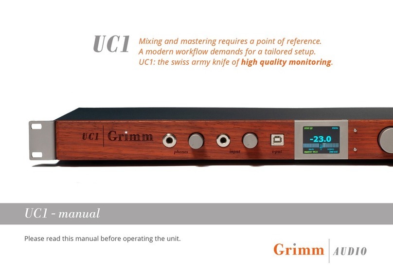
Grimm Audio UC1 User manual

Please read this manual before operating the
unit.
The Grimm Audio UC1 is a high quality Mastering and
Mixing Universal Converter oering very broad digital
application functionality. This ‘quick guide’ covers the
specic functionality for use in an Audiophile System.
Please read this manual before operating the unit.
HiFi DAC quick start guide

Quick Start Guide UC1-HiFi © Grimm Audio
2
Table of Contents
1. Introduction 3
2. Signal Connections 6
3. Operation 8
4. Menus 10
5. Source Routing & Settings Examples 17
Table of Contents

3
1. Introduction
The Grimm Audio UC1 is a high quality Mastering and
Mixing Universal Converter oering very broad digital
application functionality. This manual, however, covers
the specic functionality for use in an Audiophile
System.
Please read this manual before using the UC1 to
understand its operation and make optimal use of its
versatility as a high audiophile quality DAC / HPA / PRE.
Applications Overview
Let’s have a look at how to use the various inputs and
outputs in this context.
DAC - The Primary Function
USB Connection :
The “rear” USB input [ Input 6 ] as well as the “front” USB
input, aka the “i-put” are connected to your digital source,
be this a Server, a Streamer or a Computer.
AES3 S/PDIF Connection :
Two rear AES3 inputs can be connected to a digital source
that has AES output, be this a Server or a Streamer.
The AES3 input can also connect a CD Transport via an
AES > Coax adapter cable. Note that some high end CD
Transports oer Master/Slave clock connection, such as
the C.E.C. TL2N. The UC1’s superior clock output can in
this case can act as the Master when connected to the
clock input of the Transport. The UC1’s clock quality
equals that of Grimm Audio’s CC1 and CC2 master clocks.
When the UC1 is used as a standalone audiophile DAC
and / or a monitor controller, the clock settings need to
selected accordingly in the UC1’s “F2” function menu.
PRE - Monitor Function
XLR Analog Loudspeaker Connection :
The UC1 oers 3 analog XLR outputs. One of these output
pairs, preferably “Ana Out 3|4”, can connect directly to a
pair of active loudspeakers via their respective XLR inputs.
(Continued)
1. Introduction
Quick Start Guide UC1-HiFi © Grimm Audio

Quick Start Guide UC1-HiFi © Grimm Audio
4
A secondary loudspeaker system can connected to a
dedicated XLR output pair [ “2nd Out” ] that runs in parallel
to the Headphone output situated on the front panel.
Digital RJ45 Loudspeaker Connection :
This dedicated connection connects directly to a pair of
Grimm LS1 or PMC loudspeakers via their respective
inputs.
In the menu you select to which Output the Loudspeaker
system is connected. Although not typical in the Hi
Universe, please note that the UC1 oers several
interesting Pro Audio monitor settings such as “Mono”,
“Side”, and “Stereo Swap”.
PRE - Gain & Control Functions
Gain / Volume / Mute / Polarity & Settings :
As the UC1 is a Pro Audio component, Gain - which can be
increased or decreased via the volume dial knob - is
expressed in positive or negative “dB deviation” from a
reference loudness level nominally called “0dB”. This level
is by convention expressed in “db SPL”. This level
corresponds to an SPL of 79db in a small recording room.
To adjust the UC1 to the HiFi usage convention, reset the
default -8dB setting under the P2 function to -18db which
eectively equals an output level of 0VU. The DAC’s output
clips at +18db (5Vpp), so the gain would cover a range of
-18dB > +18dB.
Please note that the Volume and Mute functions are
available for all input / output signal paths, but in the
absence of a basic remote, these need to be adjusted
manually. News : A remote control 3.5 mm socket on the
back panel is for future use and is not yet enabled.
This is not really an issue as in almost all cases the UC1 as
a standalone DAC will be connected to modern HiFi
ampliers with “remote”. “Mute” is selected in “F1”.
The signal’s Polarity can be inverted in “P2”, but note that
this function is only available for Headphone Out signals
traversing the “Foldback Route”, which, if used, needs to
be activated in “F1”.
Furthermore, the ‘Foldback’ function is limited to two
output paths, notably to Headphone and 2nd Out .
(Continued)
1. Introduction

Quick Start Guide UC1-HiFi © Grimm Audio
5
PRE - Headphone Function
6.35mm / 1/4” Jack Connection :
The UC1 oers a 6.3mm headphone output with gain
control. The acoustic sensitivity of headphones on the
market varies by as much as 30 dB. Consumer ear buds
are more or less standardized on a sensitivity of
approximately -14 dBu (~0.15V) for 100 dBA. Some
professional 600 Ohm headphones however may need as
much as 15 dBu (~4.4V) to reach 100 dBA. This example is
of an HP with a sensitivity of 85dB/mw. The UC1 is
targeted at the professional audio market and therefore
oers enough gain to drive these types of demanding
headphones. The majority of HiFi audio headphones are
far less demanding and, as such, the UC1 will
drive these with ease.
The Headphone output circuit runs through the Foldback
route of UC1. As such, the Mute and Polarity Inversion
functions are available. HP output volume can be
controlled via the dial knob directly next to the output
jack. Switching between HP and Loudspeaker monitoring
can be done by briey depressing the main dial at the far
right of the front panel.
PRE - Analog In
XLR Connection :
This input was intended for recording analog signals for
mixing / mastering purposes. It does not serve as a typical
analog input to which rst gain is applied before
being“passed-through” to the UC1’s analog outputs.
In eect, any Analog signal input would be converted by
the A/D chip circuit to digital … and then reconverted back
to analog by the D/A chip circuit.
This may be useful only if the UC1 is connected to a pair of
active loudspeakers, and where it is not connected to a
Preamplier > Amplier > Loudspeaker system chain.
In extremis, It would be imaginable that if one wanted to
connect a Turntable with a dedicated Line stage with
integrated Phono to this analog input via RCA > XLR cable
adapters, one could in fact do so. The SQ output post A/
D/A conversion would be “acceptable”. This would also
apply to the connection of a Reel-to-Reel tape machine.
1. Introduction

6
2 A. Signal Connections - Front Panel
2. Signal Connections
Display
Head-Fi
Headphone
Controls
VOL / MUTE
POLARITY
Analog In
eg. MP3 Player
Controls
VOL / MUTE
Note : Z=1Mohm
USB In #2
Server/Laptop
Controls
VOL / MUTE
POLARITY
Main Controls
Settings
F = Functions
P = Preferences
Main Controls
Settings
Source
Volume
Quick Start Guide UC1-HiFi © Grimm Audio

7
2 B. Signal Connections - Back Panel
2. Signal Connections
USB In #1
Server/Laptop
Controls
VOL / MUTE
From
Grimm MU1
AES>AES Cable
CD Transport
AES>RCA Cable
To
Amplier 3
XLR Cable
Output CTL
VOL / MUTE
POLARITY
To
Amplier 2
or Active Speaker
XLR Cable
Output CTL
VOL / MUTE
To
Amplier 1
XLR Cable
Output CTL
VOL / MUTE
Clock Out
CD Transport
Example
CEC TL2N
Quick Start Guide UC1-HiFi © Grimm Audio

Quick Start Guide UC1-HiFi © Grimm Audio
Buttons and display
Most functions of the UC1 are adjusted via the main dial
and the two control buttons on its left side. Additionally
there are knobs for the phones output gain and the jack
input gain.
The main dial can be turned and pushed. In normal
operation, turning changes the gain of all monitor paths
(main, 2nd and phones) and pushing mutes the
speakers while engaging the headphones output on the
front. When press-holding the main dial, the current
monitor source (indicated top left of the display) starts
Main screen, USB 1/2 selected
3. Operation
blinking. Keep pressing the main dial while turning it to
change the monitor source. All inputs and outputs can
be selected. Their name is shown in the display and
their channels are highlighted in the meter. When
releasing the dial the indicated source stays selected.
Alternatively, release the dial when the blinking starts.
Then turn to select a source and press to conrm.
The large number in the display indicates the current
monitor gain level in dB’s. The monitor outputs oer 8
dB of clean gain above ‘0’ on the display. In other words:
a full scale signal will only reach full scale on a monitor
output if the monitor gain is set to +8 dB. This may
seem odd, but the idea is that the ‘0’ indication of the
display is your reference playback level to which you
always return after a louder of softer playback. This is
common practice in mastering. The ‘0’ level is usually
aligned with an SPL of 79dBC when playing a SMPTE
reference noise signal on a single channel. The Grimm
LS1 is factory aligned to that, you may adjust the gain of
your 3rd party amplier to achieve the same result - or
to select another acoustic SPL that suits you as
reference playback level. In case you feel the need to
(Continued)

9
3. Operation
adjust the ‘0’ level of the UC1, you can change it in menu
P2 (see chapter 6. Menus).
Note that the monitor gain can be set to display values
up to +18, which means that there is 10 dB of positive
gain available in the UC1 to audition very soft noises.
Note that any signal above -10 dBFS will in that case clip
– please use this extra gain with caution!
The volume control is in 0.5 dB steps above -17 dB and
1 dB below it. If you have a Grimm Audio LS1 or PMC
digitally controlled loudspeaker connected to the
proprietary cat 5 output on the back, the volume control
Main screen, Digital 1/2 selected, in phones mode
takes place in the DSP of the loudspeaker. In all other
cases the volume control is in the DSP of the UC1. At
volume setting ‘+8’ the data to the digital output and build-
in DACs is put through transparently. At other levels the
digital gain control is properly dithered at 24 bits.
Optionally, volume control of the main out can be disabled
in the menu. In that case the indicated monitor gain only
applies to the 2nd out and phones.
The knob to the right of the phones jack can be used to
align the headphones’ acoustic level with that of your main
monitor system. The idea is to switch between speakers
and phones (removing your headphones when listening to
the speakers) and adjust this control until speakers and
phones sound equally loud to you. From then on just use
the main dial for changing your monitor gain and leave the
phones control at its calibrated level.
In the bottom left corner of the display the clock status of
the UC1 is indicated. The clock source can be set manually.
Please refer to the menu chapter for instructions.
Quick Start Guide UC1-HiFi © Grimm Audio

Quick Start Guide UC1-HiFi © Grimm Audio
10
4. Menus
The UC1 has many functions, preferences and system
setup items that can be controlled from the menu. To
enter the menu, press the top button with ‘menu’ next
to it on the display. You will see a screen with 6 tabs,
labeled F1 and F2 for Functions, P1, P2 and P3 for
Preferences and S1 for System info. We walk you
through all these settings in the pages below. To move
to the next tab, press the top button ‘next tab’. To exit
the menu, press the bottom button ‘exit’. Note that the
exit button is disabled when an option is selected and
its arrow is blinking. Turn the main dial to select a
function, press to change it, then turn to browse the
options and press again to conrm your choice.
F1 menu
Whenever you enter the menu, the F1 page will be
available rst. This page gives access to monitor
functions that are often used.
• Monitor source. You can select all inputs and outputs
here by pressing the main dial briey (the arrow starts
blinking) and then turning the dial. When you reach the
last source, the order wraps and the rst source
appears again. To conrm a choice, press the dial again
(the arrow stops blinking). This item does the same as
press-hold the main button and then turn. The result is
immediately visible in the left top corner of the display,
and the selected source becomes audible.
Grimm LS1 customers, please note that the UC1 cannot
select the analog and digital inputs of the LS1 as a
source. In case you need to access these, please use the
(Continued)
F1 menu.
4. Menus

11
LS1 PC Remote software with the UC1. It is not possible
to combine the UC1 with the LS1r hardware controller
and LS1i USB interface. The UC1 replaces these.
• Special. After a press of the dial the choices are stereo
/ mono / side / swap. Note that mono = L+R and side =
L-R (they are also known as ‘M’ and ’S’). “Swap” ips the
left and right channels . At the end of the dial the order
wraps back to stereo again. This makes it possible to AB
Compare stereo & mono, mono & side and swap & stereo.
If you conrm a choice by pressing the dial once more, the
arrow stops blinking. If you then exit to the main screen
the function is shown in the screen (except for ‘stereo’,
which is the normal state).
• Foldback. When in the main screen - as a quick access
feature - a single press of the bottom button turns o and
on foldback (in case a foldback source was selected in the
menu).
• Mute. To mute the loudspeakers from the main screen
you just press the main dial. This turns o the selected
speakers and turns on the phones at the same time: it
toggles between speakers and phones.
4. Menus
Quick Start Guide UC1-HiFi © Grimm Audio

Quick Start Guide UC1-HiFi © Grimm Audio
12
F2 menu
• Clock. This setting is only available when the back USB
is not connected to a computer (normally the USB host
controls the UC1 clock). It allows you to choose all
sample rates from 44.1 to 192 kHz in master mode, or
to slave to word clock, digital in 1 or digital in 2.
• Autoswitch clock. This setting inuences the UC1
behavior when in slave mode. When ‘yes’ the UC1 clock
rate will follow any change of the selected clock source.
When ‘no’, the UC1 will maintain the clock rate that it
found when rst slaving to the selected clock source. If
the source then switches sample rate, the clock
indication on the display will turn red and start ashing
to indicate it lost lock. The ‘no’ mode is helpful when you
are running a project with a specied sample rate and it
should keep running at that rate, even when by accident
the source that you sync to changes sample rate.
• 2nd out. This ips the monitor path to the 2nd speaker
output XLR’s on the back (main and phones are muted).
• Compare mode. This mode is used when comparing
two sources at equal loudness, for instance when
evaluating the impact of a compressor/limiter in the
analog loop. Usually the external processor will have
changed the signal’s loudness and when ipping
between the two sources, this loudness jump hampers
a proper quality judgement. In compare mode the
volume setting is memorized for every source
(Continued)
F2 menu.
4. Menus

13
individually instead of global. So if you listen to the rst
source, adjust the volume to taste, then switch to the
second source and adjust that volume to a similar level,
ipping between the two sources can be done at equal
loudness. To indicate that compare mode is engaged,
the volume number turns green.
P1 menu
The P1 menu is the rst of three Preference menus.
These are settings that are usually only changed to tailor
the UC1 to your system setup.
P1 menu.
4. Menus
• Main out. Here you select your main monitor output.
There are three options: LS1 / PMC on cat5, Dig out 1|2
and Ana out 1|2. The selected output will receive volume
control and monitors the audio from the monitored
sources. Their playback will be interrupted when another
monitor source is chosen.
• Max in Analog 1|2. This preference let’s you choose
between 18 dBu or 24 dBu as maximum modulation (0
dBFS) input voltage. The default is 18 dBu (all UC1 outputs
have a maximum modulation at 18 dBu).
In case a vintage device is used into your analog input, and
that you like to drive to maximum swing, you can change
this setting to 24 dBu.
• Main out volume. By default it is turned on. Some people
prefer to use an external analog volume control in stead
of the internal digital one. They can disable the main out
volume control here. Volume control of 2nd out and
headphones will still work.
• PC control (midi/volume). Not Applicable to this
application.
Quick Start Guide UC1-HiFi © Grimm Audio

Quick Start Guide UC1-HiFi © Grimm Audio
14
P2 menu
• Monitor mode. In ‘normal’ mode the three monitor
outputs (main, 2nd speaker and phones) alternate. Only
one is active at a time. In ‘split’ mode the 2nd speaker
and phones paths are decoupled from the monitor
system and become an independent path for USB 9&10,
without any digital volume control. The 2nd out and
phones channels carry the same signal and are always
on. The rightmost channels in the meter display now
show the USB 9&10 levels in stead of the monitor
output levels.
• Soft key. Here the function of the bottom button in the
main screen can be selected. You can choose between:
2nd out (switch to 2nd speaker output); special (enable
the selected ‘special’ function from menu F1, like mono
or side); dim 20 dB (attenuate the output by 20 dB);
compare mode (enable the compare mode of menu F2);
fast 0 dB (set the volume level to the current reference
level).
• Phones phase. This ips the polarity of the
headphones output. Since there is no ocial standard
for the relationship between the electrical signal polarity
and the acoustical pressure polarity of headphones, a
positive going electric pulse can result in a pressure
increase on some brands’ headphones and a pressure
decrease on others. The UC1 polarity switch can be
used to achieve a positive polarity with your
microphone / headphones combination so that an
increase in pressure in front of your microphone will
result in an increase in pressure inside your
headphones.
(Continued)
P2 menu.
4. Menus

15
Since headphones always show some leakage from
environmental sounds, selecting the right polarity will
improve the coherence of the leaked acoustic sound.
• Ref level. When this line is selected, a press on the
main dial stores the current volume level as the ‘0 dB’
reference playback level. The default setting is -8 dB,
which means that the UC1 monitor output has 8 dB of
gain available above the reference setting. If you need
more or less ‘excess gain’, you may change it here.
4. Menus
Quick Start Guide UC1-HiFi © Grimm Audio

Quick Start Guide UC1-HiFi © Grimm Audio
16
P3 menu
• Display brightness. This function controls the
brightness of the display from 1 to 10.
• Display auto dim. If auto dim is turned on the display
will turn o a few seconds after a control is used.
• Main screen meters. This enables or disables the
presence of a simple 3-stage meter on the main screen.
S1 menu
This menu shows the hardware and rmware versions
of your UC1. It also shows if the UC1 is booted in LS1
mode or PMC mode.
4. Menus
P3 menu. S1 menu.

A. Routing USB1 |Server/Streamer - Rear Panel
Figure 2a on page 18 shows the routing diagram of the
UC1 for the USB1 input connection on the rear panel.
The selected output shown is Ana 3|4 which bypasses
all functions and controls. To allow all functions and
controls, select output Ana 1|2 (aka Main) or “2nd Out”.
B. Routing USB I-put |Server/Streamer - Front Panel
Figure 2b on page 19 shows the routing diagram of the
UC1 for the USB “I-put” connection on the front panel.
The selected output shown is “2nd Out”, and all controls
and functions are enabled. If “Phones” and “polarity” are
not desired, select output Ana 1|2.
C. Routing Grimm MU1 Server/Streamer
Figure 2c on page 20 shows the routing diagram of the
UC1 for the Grimm MU1 connected to AES3 Dig 1/2.
The selected output shown is “2nd Out”, and all controls
and functions are enabled. If “Phones” and “polarity” are
not desired, select output Ana 1|2.
D. Routing CD Transport
Figure 2d on page 21 shows the routing diagram of the
UC1 for a CD Transport connected to AES3 Dig 2/2,
The selected output shown is “2nd Out”, and all controls
and functions are enabled. If “Phones” and “polarity” are
not desired, select output Ana 1|2.
5. Source outing Examples
Suggested Routing & Settings - Source Specic
This section covers suggested routing and settings for 4 Digital Source options - 3 server / streamers, and a CD Transport.
A brief description of each is shown below, and is illustrated by a diagram on pages 18-21.
Quick Start Guide UC1-HiFi © Grimm Audio
17
5. Source Routing Examples

A. outing USB 1 | Back
USB 1 -12.0 next tab
USB 1 | F1 settings
F1 F2 P1 P2 P3 S1
> monitor source : USB 1
special : stereo |mono
foldback : on | o
mute : on|o
master 44.1 exit
USB 1 -12.0 next tab
USB 1 | F2 settings
F1 F2 P1 P2 P3 S1
clock master 44.1
autoswitch clock : yes |no
2nd out : on |o
compare mode : on |o
master 44.1 exit
USB 1 -12.0 next tab
USB 1 | P1 settings
F1 F2 P1 P2 P3 S1
> main out : Ana Out 3|4 2nd Out 1|2
max In Analog 1|2 : 18 dBu
main out volume : on | o
compare mode : on|o
master 44.1 exit
USB 1 -12.0 next tab
USB 1 | P2 settings
F1 F2 P1 P2 P3 S1
> monitor mode : normal
softkey : 2nd Out
phones phase : normal |inverted
ref level : 0dB |- 12.0dB
master 44.1 exit
1
Figure 2a UC1- HiFi internal routing.
Out LS 1/2, Ana
1/2, Dig 1/2
(when not Main)
Routing
Stereo / mono
Mix
Volume, mute
and polarity
SB (back) In
Special (mono/
side/swap)
Volume and mute
Phones & 2nd out
Main out
Foldback
SB 1-8
Monitor
SB 7/8
Out Ana 3/4
2 channels
2 channels
2 channels
5. Source Routing Examples
Settings
1. Using the main VOL / Source Dial, select
the USB1 input under F1.
2. Via the two setting buttons, scroll
through and select the F1, F2, functions
and the P1 and P2 Preferences as shown.
3. The P2 “reference level” can preferably
be between -8 and -18 … e.g. -12
4. The Clock master setting for this source’s
playback will automatically set itself to
the source clock when ”autoswitch clock”
under F2 is set to “yes”.
Quick Start Guide UC1-HiFi © Grimm Audio

Routing
Stereo / mono
Mix
Volume, mute
and polarity
Special (mono/
side/swap)
Volume and mute
Phones & 2nd out
Main out
[ Analog Out 1&2 ]
Foldback
Monitor
2 channels
SB (back) Out
DAC #2
B. outing USB 2 | i-put
i-put USB -12.0 next tab
i-put USB F1 settings
F1 F2 P1 P2 P3 S1
> monitor source : i-put USB
special : stereo |mono
foldback : on|o
mute : on|o
master 44.1 exit
i-put USB -12.0 next tab
i-put USB | F2 settings
F1 F2 P1 P2 P3 S1
clock master 44.1
autoswitch clock : yes |no
2nd out : on |o
compare mode : on |o
master 44.1 exit
i-put USB -12.0 next tab
i-put USB | P1 settings
F1 F2 P1 P2 P3 S1
> main out : Ana Out 1|2 2nd Out 1|2
max In Analog 1|2 : 18 dBu
main out volume : on|o
compare mode : on|o
master 44.1 exit
i-put USB -12.0 next tab
i-put USB | P2 settings
F1 F2 P1 P2 P3 S1
> monitor mode : normal
softkey : 2nd Out
phones phase : normal |inverted
ref level : 0dB |- 12.0dB
master 44.1 exit
Input - AES3 #2
CD Transport
Input - SB 2
i-put Hi-Z ¼” - Front (2)
Analog XLR - Rear (2)
C1 Pro application Only
- Rear (2)AES3 #1
AES3 #2 - Rear (2)
19
Figure 2b UC1- HiFi internal routing.
2nd SB - Front (2)
5. Source Routing Examples
Settings
1. Using the main VOL / Source Dial, select
the “I-Put USB” input under F1.
2. Via the two setting buttons, scroll
through and select the F1, F2, functions
and the P1 and P2 Preferences as shown.
3. The P2 “reference level” can preferably
be between -8 and -18 … e.g. -12
4. The Clock master setting for this source’s
playback will automatically set itself to
the source clock when ”autoswitch clock”
under F2 is set to “yes”.
Quick Start Guide UC1-HiFi © Grimm Audio

Routing
Stereo / mono
Mix
Volume, mute
and polarity
Special (mono/
side/swap)
Volume and mute
Phones & 2nd out
Main out
[ Analog Out 1&2 ]
Foldback
Monitor
2 channels
SB (back) Out
DAC #2
Input - AES3 #1
GRIMM MU1
C. outing MU1
Dig In 1|2 -12.0 next tab
Dig In 1|2 | F1 settings
F1 F2 P1 P2 P3 S1
> monitor source : Dig In 1|2
special : stereo |mono
foldback : on|o
mute : on|o
master 44.1 exit
Dig In 1|2 -12.0 next tab
Dig In 1|2 | F2 settings
F1 F2 P1 P2 P3 S1
clock master 44.1
autoswitch clock : yes |no
2nd out : on |o
compare mode : on |o
master 44.1 exit
Dig In 1|2 -12.0 next tab
Dig In 1|2 | P1 settings
F1 F2 P1 P2 P3 S1
> main out : Ana Out 1|2 2nd Out 1|2
max In Analog 1|2 : 18 dBu
main out volume : on|o
compare mode : on|o
master 44.1 exit
Dig In 1|2 -12.0 next tab
Dig In 1|2 | P2 settings
F1 F2 P1 P2 P3 S1
> monitor mode : normal
softkey : 2nd Out
phones phase : normal |inverted
ref level : 0dB |- 12.0dB
master 44.1 exit
2nd SB - Front (2)
Hi-Z ¼” - Front (2)
AES3 #2 - Rear (2)
Analog XLR - Rear (2)
C1 Pro application Only
- Rear (2)AES3 #1
20
Figure 2c UC1- HiFi internal routing.
Settings
1. Using the main VOL / Source Dial, select
the Dig 1|2 input under F1.
2. Via the two setting buttons, scroll
through and select the F1, F2, functions
and the P1 and P2 Preferences as shown.
3. The P2 “reference level” can preferably
be between -8 and -18 … e.g. -12
4. The Clock master setting for this source’s
playback will automatically set itself to
the source clock when ”autoswitch clock”
under F2 is set to “yes”.
5. Source Routing Examples
Quick Start Guide UC1-HiFi © Grimm Audio
Other manuals for UC1
1
Table of contents
Other Grimm Audio Media Converter manuals