Kramer Electronics Ltd.
6
Composite Video - use the composite video cable provided to connect from the composite video output
on the back of the Scan Converter (the BNC connector marked CV) to the composite video input of your
target video equipment.
S-Video - use the S-Video cable provided to connect from the S-Video output on the back of the Scan
Converter to the S-Video input of your target video equipment. S-Video provides improved performance
over Composite Video.
RGB with Composite Sync - Use a 4xBNC to 4xBNC cable to link from the Red, Green, Blue, and
HS/CS outputs to the video display. The Scan Converter defaults to outputting negative-going CS
(Composite Sync) on the HS/CS connector, but if you encounter problems then it is likely that this has
been changed - see 'Advanced Features' later in this manual. Please note that this output’s horizontal
scan rate is 15.75KHz and is not intended for connection to a computer monitor.
RGB with H&V Sync - Use a 5xBNC to 5xBNC cable to link from the Red, Green, Blue, HS/CS and
VS outputs to the video display. Since the Scan Converter defaults to outputting CS (Composite Sync)
on the HS/CS and VS connectors, so you must see 'Advanced Features' later in this manual in order to
change this to the required separate H&V Syncs. It is recommended that another output be used, until
operation of the unit is understood.
YUV Component (Y,R-Y,B-Y)- Use a 3xBNC to 3xBNC cable to link from the Y, R-Y and B-Y
outputs to the video display. If the Scan Converter is set to output RGB mode (this is the default) it will
be necessary to switch to YUV. See the section on switching between RGB and YUV modes in the
Advanced Features section of this manual. It is recommended that another output be used, until
operation of the unit is understood, because in the YUV Mode, no other video output signals are present.
5.4 Optional Connection of an External Reference Signal (N/A on VP-704SC)
The VP-705SC and VP-706SC have the ability to synchronize their video output with a master Reference
Signal, in the form of a Composite Video or Blackburst source. This is done by connecting the Reference
Signal to the BNC connector marked 'GL IN'. A loop-through output is available at the 'GL OUT' BNC
connector for connection to other devices. Note - If no loop-through is required, you must connect the supplied
75 Ohm BNC termination plug to the 'GL OUT' connector instead; otherwise, the unit may not be able to
maintain a lock on the Reference Signal.
Synchronization is not automatic; you need to enable it within the unit. You should also ensure that the
Composite Video or Blackburst signal used is of the right standard (PAL or NTSC), and that it is a clean, stable,
standard signal. Video signals from consumer VCRs and some non-standard equipment may not be suitable.
5.5 Connecting the Serial Cable
The Scan Converter can be controlled from a computer, and used as a remote Microsoft® serial mouse emulator
by connecting its RS-232 port to a computer's RS-232 port. See the section on 'RS-232 Computer Control' later
in this manual on how to use this control feature (RS-232 Control is the default, and merely requires connecting
a suitable RS-232 cable).
5.6 Connecting the AC Power
The Scan Converter requires an AC input power source of 100-240VAC@50-60Hz. With the Power On/Off
switch on the rear of the Scan Converter in the Off position, plug the AC Cable supplied into the AC Receptacle
on the back of the unit and plug the AC Cable into the power outlet.
5.7 Turning the Scan Converter On
Make sure that all cables are connected and that all other equipment is turned on - your computer monitor
should be functioning normally. The Scan Converter’s AC Power Switch on the rear panel should be switched
on. When using a multi-purpose TV-Monitor, be sure and select the correct line input (AUX or AV). The video
monitor should now be displaying the same picture as is on the computer monitor.
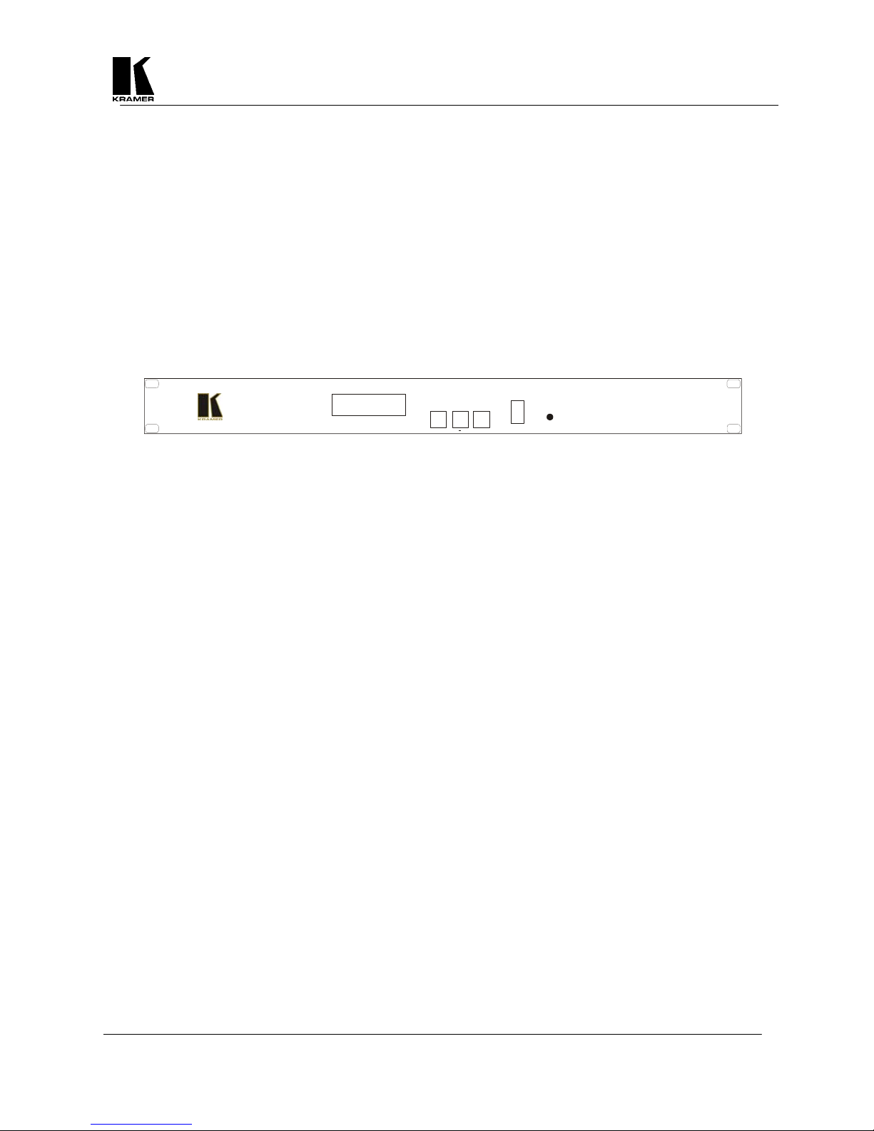
When the Scan Converter is switched on, the green LED indicator on the front panel will illuminate. If there is a
picture on the video monitor, but it is the wrong shape, position or color it may be necessary to alter some of the
status settings before a good picture is displayed. For example, it may be necessary to switch to PAL or NTSC
settings. Further details on selecting the correct settings for your displays follow in the Advanced Features
section. If there is no picture on the video monitor, then go to the Troubleshooting section.