manuals.online logo
Brands
  1. Home
  2. •
  3. Brands
  4. •
  5. Lumel
  6. •
  7. Media Converter
  8. •
  9. Lumel PD8 User manual

Lumel PD8 User manual


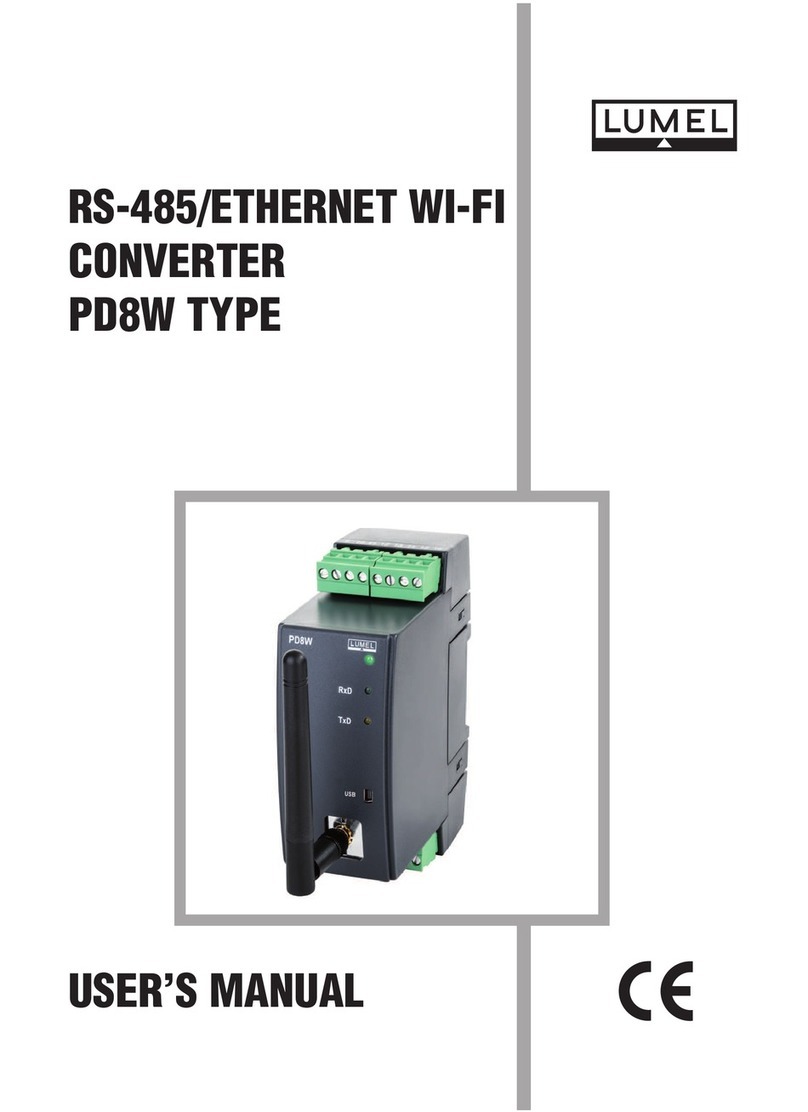
USERS MANUAL
RS-485/ETHERNET
CONVERTER
PD8 TYPE
!
CONTENTS
1. APPLICATION .............................................................................................. 5
2. PD8 CONVERTER SET ...............................................................................5
3. INSTALLATION AND BASIC SAFETY REQUIREMENTS........................... 8
3.1. Converter installation ........................................................................... 10
3.2. PD8 electrical connections ................................................................... 10
3.3. Connection way with devices ............................................................... 12
3.4. Requirements or lead-out connections ................................................ 13
3.5. Transmission parameters o the serial inter ace ................................... 14
3.6. Con iguration o PD8 network settings ................................................. 14
3.6.1. Installation o the « PD8Con ig.exe » so tware .......................... 15
3.6.2. Description o the con iguration so tware ................................... 15
3.7. Capabilities to con igure PD8 ............................................................... 17
3.7.1. Installation o the PD8 con iguration applet service
component on a PC computer ................................................... 18
3.7.2. Notes concernig the con iguration applet
in the users browser ................................................................. 18
3.7.3. Change o authorisation data ..................................................... 19
4. OPERATION MODE WITH REALPORT SERVICE ..................................... 8
4.1. In ormation about RealPort service controller iles ............................... 13
4.2. Example o controller installation in Windows XP ................................ 13
4.3. Con iguration o RealPort controller in Windows XP ............................ 13
4.4. Example o LUMEL HEAT and LUMEL ENERGY con iguration
to co-operate with PD8 ........................................................................ 13
RS-485/ETHERNET CONVERTER
PD8 TYPE
USERS MANUAL
"
5. SERIAL BRIDGE MODE WITH UDP PROTOCOL .................................... 25
5.1. Settlement o serial link transmission bu ering .................................... 13
5.2. Operation con iguration o the serviced client ...................................... 13
5.3. Setting o the serial transmission server .............................................. 13
5.4. Managing o the service server ............................................................ 13
6. TECHNICAL DATA ..................................................................................... 27
7. ORDERING CODES ................................................................................... 27
8. MAINTENANCE AND WARRANTY ........................................................... 28
#
1. APPLICATION
The PD8 converter allows to transmit data to the master devices through the
computer network o Ethernet type, to devices equipped with the RS-485 inter ace.
The converter is available in two versions concerning its operation manner: Real-
Port network service and serial bridge with UDP protocol.
In the version nr 1, the PC computer with the Ethernet network card is the connected
master device. In the version nr 2, the converter co-operates with the device with the
master unction and the RS-485 serial inter ace. The version nr 1 o the PD8 conver-
ter requires the installation o a programmed controller o the virtual serial port on the
PC computer with the Windows system.
This controller ensures to present-days master systems, e.g. LUMEL-HEAT and
LUMEL-ENERGY systems, the possibility to transmit data between devices with
RS-485 inter ace, through the Ethernet network, thanks the use o converters o
PD8 type (Fig. 1). The converter used in this manner enables to co-operate only with
one master computer in the giving moment.
In case o using PD8 or servicing MODBUS and LUMBUS industrial protocols - its
correct co-operation with master systems on a PC depends on their built-in
mechanisms to control break-time intervals between received transmission
characters. When using PD8 in the version nr 2, one can develop the RS-485 bus
with successive segments by means o additional PD8 converters and the local
Ethernet network.
The suitable con iguration, at least o one pair o converters, allows to obtain their
operation in the serial bridge mode (Fig. 3.). The con iguration o their operation
is also possible in the mode one-to-several ( in the shape o a set including
maximally 65 converters - Fig. 4.)
The version nr 2 operates in the local Ethernet network servicing the UDP
datagram protocol.
2. PD8 CONVERTER SET
The converter set is composed o :
- PD8 converter 1 pc
- PD8 users manual 1 pc
- warranty card 1 pc
- mini CD with so tware 1 pc
When unpacking the converter, please check the delivery completeness and
whether the type and version code on the data plate correspond to the order.
$
ETHERNET
Local
network
2,&
RG24
controller
N10
eter
N12
eter
ETHERNET
RS-485
Fig. 1. Exemplary application of the PD converter (version Nr1) in a local computer network.
PD21
on entrator
PC omputer
Distinct individual
address IP:
192.168.0.1
Permanent private
Address IP
192.168.0.145
%
ETHERNET INTERNET
ETHERNET
2,&
RS-485
RS-485
PD21
concentrator
N10
eter
N12
eter
Router Router
RG24
controller
Per anent public
IP Address:
pd8.lu el.co .pl
Fig. 2. Exemplary application of the PD converter (version nr 1) in an vide area computer network.
PC omputer
Distinct public
IP Address:
Station.lumel.com.pl
&
ETHERNET
2,&
RG24
controller
N12
eter
RS-485
Fig. 3. Exemplary application of the PD converter (version nr 2) in the serial bridge mode.
PC omputer
IP address:
10.10.0.1
IP address:
10.0.2.161
Local
network
RS-485
ETHERNET
2,&
IP address:
10.0.2.162
'
Fig. 4. Exemplary application of the PD converter (version nr 2) in the one-to-several mode.
RS-485
Supervising
device with
serial inter ace
Local
network
2,&
IP address:
10.0.2.160
2,&
IP address:
10.0.3.1
2,&
IP address:
10.0.2.65
Network
o devices
with serial
inter ace
RS-485
RS-485
Network
o devices
with serial
inter ace

3. INSTALLATION AND BASIC SAFETY REQUIREMENTS
Symbols located in this service manual mean:
WARNING!
Warning o potential, hazardous situations. Especially important. One
must acquaint with this be ore connecting the converter. The non-ob-
servance o notices marked by these symbols can occasion severe
injuries o the personnel and the damage o the instrument.
CAUTION!
Designates a general use ul note. I you observe it, handling o the
converter is made easier. One must take note o this, when the instru-
ment is working inconsistently to the expectations.
Possible onsequen es if disregarded !
In the security scope the converter meets the requirements o the EEC Low-Voltage
Directive (EN 61010 -1 issued by CENELEC).
Remarks on erning the operator safety:
1. General
lThe PD8 converter is destined to be mounted on a panel.
lNon-authorized removal o the required housing, inappropriate use, incorrect
installation or operation creates the risk o injury to personnel or damage to
equipment. For more detailed in ormation please study the Users Manual.
lAll operations concerning transport, installation, and commissioning as well
as maintenance must be carried out by quali ied, skilled personnel and
national regulations or the prevention o accidents must be observed.
lAccording to this basic sa ety in ormation, quali ied, skilled personnel are
persons who are amiliar with the installation, assembly, commissioning, and
operation o the product and who have quali ications necessary or their
occupation.
2. Transport, storage
lPlease observe the notes on transport, storage and appropriate handling.
lObserve the climatic conditions given in Technical Data.
3. Installation
lThe meter must be installed according to the regulation and instructions
given in this Users Manual.
lEnsure proper handling and avoid mechanical stress.
!
?

lDo not bend any components and do not change any insulation distances.
lDo not touch any electronic components and contacts.
lInstruments may contain electrostatically sensitive components, which can
easily be damaged by inappropriate handling.
lDo not damage or destroy any electrical components since this might
endanger your health!
4. Electrical connection
lBe ore switching the instrument on, one must check the correctness o
connection to the network.
lIn case o the protection terminal connection with a separate lead one must
remember to connect it be ore the connection o the instrument to the mains.
lWhen working on live instruments, the applicable national regulations or the
prevention o accidents must be observed.
lThe electrical installation must be carried out according to the appropriate
regulations (cable cross-sections, uses, PE connection). Additional
in ormation can be obtained rom the users guide.
lThe documentation contains in ormation about installation in compliance with
EMC (shielding, grounding, ilters and cables). These notes must be
observed or all CE-marked products.
lThe manu acturer o the measuring system or installed devices is responsible
or the compliance with the required limit values demanded by the EMC
legislation.
5. Operation
lMeasuring systems including PD8 converters, must be equipped with
protection devices according to the corresponding standard and regulations
or prevention o accidents.
lA ter the converter has been disconnected rom the supply voltage, live
components and power connections must not be touched immediately
because capacitors can be charged.
lThe housing must be closed during operation.
6. Maintenance and servicing
lPlease observe the manu acturers documentation.
lRead all product-speci ic sa ety and application notes in this Users Manual.
lBe ore taking the converter housing out, one must turn the supply o .
lThe removal o the converter housing during the guarantee contract period
may cause its cancellation.

3.1 Converter installation
The PD8 converter is oreseen to be installed on a 35 mm DIN rail in accordance
with the ig. 3.
Fig. 3. Overall and assembly dimensions
3.2. PD8 electrical connections
The supply and external signals must be connected acc. to ig. 4 and 5 and
tables 1 and 2, in which the assignment o particular PD8 converter lead-outs have
been described.
There are three diodes on the converter rontal plate:
lGreen - signalling the supply switching on
lRed (RxD) - signalling the data reception through RS-485
lYellow (TxD) - signalling the data broadcasting through RS-485
1
9
2
10
3
11
4
12
5
13
6
14
7
15
8
16
100 45
120
!
SUPPLY
RS-485
1
9
2
10
3
11
4
12
5
13
6
14
7
15
8
16
ETHERNET
Description of PD8 converter leads-out Table 1
Terminal Terminal des ription
6Mass of RS-485 interface with optoisolation
7Line A of RS-485 interface with optoisolation
8Line B of RS-485 interface with optoisolation
9, 10 Lines to supply the converter
In the RJ-45 socket o the Ethernet inter a-
ce 2 diodes are located:
lgreen (ACT) - signalling the network
activity o the device (transmission
or reception)
lorange (LNK) - signalling the active
network connection
Fig.4
External connections of
the PD converter
Fig. 5
Frontal view of the RJ-45
Ethernet interface socket
1
8
Description of RJ-45 socket si nals Table 2
No Signal Des ription
1 TX+ Transmission +
2 TX- Transmission -
3 RX+ Reception +
4 EPWR+ (no used)
5 EPWR+ (no used)
6 RX- Reception -
7 EPWR- (no used)
8 EPWR- (no used)
"
3.3 Connection way with devices
The ig. 6 presents the manner o PD8 converter connection with devices rom the
object side with RS-485 inter ace and the computer equipped with Ethernet inter a-
ce. From the RS-485 inter ace side, the converter can be directly connected to the
RS-485 bus.
For the Ethernet inter ace, the twist o STP type (screened) o category 5, should be
set with RJ-45 plugs and the wire colouring (in accordance with the table 3) in the
ollowing standard:
lEIA/TIA 568A or both plugs, in so-called direct connection o PD8 to the
network concentrator (hub), or network switch (switch).
lEIA/TIA 568A or the irst plug or EIA/TIA 568B or the second plug in so-called
connection with a cross-over transposition, applied among other things in the
direct PD8 connection to the computer.
Fig. 6 Example of PD converter direct connection with the PC computer
1
8
8
1
GND
A
B
Ethernet able with
ross-over transposition
RS-485 bus
PC omputer
with Ethernet
interfa e
!
#
!
1 TX+ White-green White-orange
2 TX- Green orange
3 RX+ White-orange White-green
4 EPWR+ Blue Blue
5 EPWR+ White-blue White-blue
6 RX- orange Green
7 EPWR- White-brown White-brown
8 EPWR- brown brown
Wire colourin in RJ-45 plu Table 3
Wire
No Signal Wire olour in a ordan e with standard
EIA/TIA 568A EIA/TIA 568B
NOTE:
Be ause of ele tromagneti interferen e, one must use s reened wires to on-
ne t RS-485 interfa e signals. The s reen must be onne ted to the
prote tive terminal in one point.
The supply must be onne ted with a two-wire able with an appropriate wire
diameter, ensuring its prote tion by means of a fusible ut-out.
The remove of the onverter housing during the guarantee period will ause
its invalidation.
3.4. Require ents for lead connections
Occurring in practice, di erent inter erence sources in luence the converter in a per-
manent or pulse way rom the supply network side because o other devices action.
The level o this inter erence should be reduced to a value smaller than the resistan-
ce threshold, irst o all, through the appropriate installation o the converter in the
object.
In order to obtain a full immunity of the onverter against ele tro-
magneti Interferen e in an environment with unknown interferen-
e level, it is re ommended to observe following prin iples:
lThere should be a switch or a circuit breaker in the building installation. This
element should be situated near the device, easy accessible or the operator.
It should be marked as the instrument switching the device o .
lDo not supply the converter rom the network near devices generating high
pulsing inter erence.
!
$
lApply network ilters or groups o modules servicing the same object.
lApply the general principle that the wires (group o wires) leading di erent
signals should be led in the possible arthest distance between them (not less
than 50 cm) and the crossing o such group o wires should be made at right
angle.
lTaking into consideration electromagnetic inter erence, one must use shielded
wires to connect RS-485 inter ace signals. The shield must be connected to
the protective terminal in a single point. The supply must be connected by
two-wire cable with a suitable cross-section ensuring its protection by means
o a cut-out.
3.5. Trans ission para eters of the serial interface
The PD8 converter co-operates rom the RS-485 side with industrial devices at ol-
lowing baud rates: 300, 600, 1200, 2400, 4800, 9600, 19200, 38400, 56000 bit/s.
Maximal serial baud rates depend on the length o transmission lines and are pre-
sented on the table 4.
At a length over 800 m. One must apply a terminator ( a 120 Ohm resistance) which
connects terminals A and B o the PD8 converter.
Dependence of maximal baud rate from the line len th Table 4
With a terminator or baud
rate > 9600 bit/s
Length of the
transmission line Maximal baud rate Notes
200 m
800 m
1200 m
56000 bit/s
38400 bit/s
9600 bit/s
Without a terminator
With a terminator
3.6. Configuration of PD8 network settings
Similarly to other network devices, the PD8 converter requires at its irst start a
suitable con iguration o settings or needs o the IP network protocol.
These settings include: IP address o the PD8 converter, subnet mask, address o the
de ault gateway. These data must be obtained rom the administrator o the computer
network, to which the PD8 converter is connected. In case o the converter connection
to the local computer network, in which the DHCP service is accessible, the PD8
%
converter will be con igured automatically owing to it.
To obtain in ormation about the IP address assigned to the converter, one must start
the PD8Con .exe on the PC computer connected to the same computer network
as the PD8.
3.6.1. Installation of the PD8Config.exe software
The installation consists on the copying o the PD8Con .exe so tware ile rom the
mini CD into the computer catalog indicated by the user. The so tware can be also
directly activated rom the mini CD diskette.
3.6.2. Description of the configuration software
The PD8Con ig.exe so tware added to the set serves to con igure network settings
o the PD8 converter.
The so tware a ter starting, searches the local computer network and creates the list
o accessible converters o PD8 series.
The list is displayed in the ield  List o Converters ( ig. 7)
The current IP address o the only one converter in the hereby example is visible in
the IP Address ield. I one can see, that the converter has an unsuitable IP ad-
dress o 0.0.0.0. type, that means, that in the given computer network, the DHCP
service does not occur. In such a case, one must con igure manually the PD8 co-
nverter with the unsuitable address, in the ollowing way:
Fig. 7 List of accessible PD converters
&
Fig. Configuration of exemplary PD network parameters
lA ter marking the given converter, click the Con igure IP settings key,
lIn the revealed Set up the IP address window, one must ul il the ields with
data obtained rom the network manager ( ig. 8). Leave empty, the ield with
the password.
lA ter pushing the Apply key in, one must wait some time till the Operation
carried out success ully message appears. A ter con irming the message,
one must click rom the main window the Re resh list command. A ter a while,
the list o accessible converters will be actualised and appears in accordance
with the ig.9.
The Reboot converter command is use ul a ter the succeeding manual network
con iguration, carried out by remote control through the computer network. Then,
new network settings in PD8 are activated only a ter the reboot start o the converter.
'
The unconditional restart o PD8 can be also per ormed by pressing the accessible
push-button through the hole in the converter housing, a ter removing the lower
terminal 5-8 o the RS-485 terminal.
Fig. 9 Correctly configured PD converter
Using the PD8Con ig.exe so tware, one can easily display the Web page served
by the indexed PD8. For this purpose, a ter the converter indication rom the list, one
must click the open Web Inter ace push-button, what occasions the start o the
de ault internet browser being in the standard accessory o any contemporary users
computer.
The PD8 onverter Web page ontains the appli ation whi h
requires the presen e of an appropriate servi e software in the
omputer. Information on erning the installation of this servi e
are in luded in the se tion 3.7.5 of this users manual.
3.7. Capabilities to configure PD8
The PD8 converter with actory settings is protected by the users name and its
password against non-authorised changes in the network con iguration and com-
mands to restart the converter again. The de ault user is root, which has the dbps
password.
?

These data can be modi ied thanks to the con iguring applet on the Web page o the
given PD8 which is called by the user by means o the internet browser installed on
its PC computer.
3.7.1. Installation of the PD8 configuration applet ser ice
component in PC
The embedded applet (application o the Java language) in the users computer.
This service is being accessible a ter installing the Java JRE service package in the
windows system. The package adds the starting plug (plug-in) to the internet brow-
ser by means o which, the user opens the Web page with the applet. The PD8
converter applet requires the JRE package in 1.4.0 versions or higher. For this re-
ason, be ore the irst opening o the PD8 page in the users browser, one must start
the installator o JRE package which exists in the Java JRE catalogue on the PD8
CD disk.
To install the applet service package into the users PC, one must carry out ollowing
operations:
1. Start the ile with extension o the (.exe in the Java JRE catalogue
o the CD disk.
2. Select the I accept the terms in the license agreement in the shown
installator window and click Next.
3. Select the typical option and click Next.
4. (Optional Installator step). Mark accessible browsers in the computer
and click Next.
5. A ter inishing the installation, click  inish in the installator window.
6. Call the PD8 Web page in the browser in order to check the JRE
installation correctness.
7. Press the always push-button in the new window with the Warning -
security title, the appearance o which means the query about acceptation
o the digital signature o the being started applet by the user.
8. Close the browser.
3.7.2. Remarks about the configuration applet in the users
browser
A ter writing the PD8 converter Web address in the browser address bar, the users
con iguration applet appears in a separate window ( ig. 10).
The le t side o the application window includes the menu o accessible commands.
The right window panel shows data associated with the command passed by the

Other Lumel Media Converter manuals

Lumel PD10 User manual

Lumel

Lumel PD10 User manual

Lumel PD10 User manual

Lumel

Lumel PD10 User manual

Lumel PD9 User manual

Lumel

Lumel PD9 User manual

Lumel PD9W User manual

Lumel

Lumel PD9W User manual

Lumel PD8W User manual

Lumel

Lumel PD8W User manual

Lumel PD12 User manual

Lumel

Lumel PD12 User manual

Lumel PD9 User manual

Lumel

Lumel PD9 User manual

Lumel S4AO User manual

Lumel

Lumel S4AO User manual

Lumel PD9 User manual

Lumel

Lumel PD9 User manual

Lumel PD51 User manual

Lumel

Lumel PD51 User manual

Popular Media Converter manuals by other brands

Altera EP53A8LQI user guide

Altera

Altera EP53A8LQI user guide

Speaka Professional 1230712 operating instructions

Speaka Professional

Speaka Professional 1230712 operating instructions

Transition Networks FD-CD-01 user guide

Transition Networks

Transition Networks FD-CD-01 user guide

Axis P7216 user manual

Axis

Axis P7216 user manual

Allen-Bradley 842E-SIP*BA installation instructions

Allen-Bradley

Allen-Bradley 842E-SIP*BA installation instructions

Nexans XPLORER Series instructions

Nexans

Nexans XPLORER Series instructions

NewTek NC1S-HDMI-3G user manual

NewTek

NewTek NC1S-HDMI-3G user manual

Vacon CX manual

Vacon

Vacon CX manual

YOKOGAWA PH450G user manual

YOKOGAWA

YOKOGAWA PH450G user manual

JRC NJU26209 manual

JRC

JRC NJU26209 manual

Korenix JetCon 2301 V2 Series Quick installation guide

Korenix

Korenix JetCon 2301 V2 Series Quick installation guide

GSS PHDQ 1000 ASI DF Assembly instructions

GSS

GSS PHDQ 1000 ASI DF Assembly instructions

Sylvania SKCR2810BT user manual

Sylvania

Sylvania SKCR2810BT user manual

CEL-MAR ADA-4010A user manual

CEL-MAR

CEL-MAR ADA-4010A user manual

GoMax Electronics CV-35AK user manual

GoMax Electronics

GoMax Electronics CV-35AK user manual

ADF Web HD67B78-A1 user manual

ADF Web

ADF Web HD67B78-A1 user manual

Moxa Technologies NPort DE-311 Hardware installation guide

Moxa Technologies

Moxa Technologies NPort DE-311 Hardware installation guide

Advantech DVP-7020 user manual

Advantech

Advantech DVP-7020 user manual

manuals.online logo
manuals.online logoBrands
  • About & Mission
  • Contact us
  • Privacy Policy
  • Terms and Conditions

Copyright 2025 Manuals.Online. All Rights Reserved.