manuals.online logo
Brands
  1. Home
  2. •
  3. Brands
  4. •
  5. Grohe
  6. •
  7. Plumbing Product
  8. •
  9. Grohe Chiara Series User manual

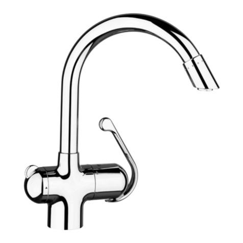
Grohe Chiara Series User manual

....18
....12
.....7
D.....1
NL
PL
GB
S
UAE
F
DK
GR
E
N
CZ
I
FIN
H
.....2
.....3
.....4
.....5
.....6
.....8
......9
....10
....11
....13
....14
....15
P....16
....17
TR
RUS
SK
SLO
....19
....20
....22
....21
HR
BG
EST
LV
....23
....24
....25
LT
33 201
97.793.231ÄM 90 775/09.03
33 001 33 003
Linie EuroplusChiara
......9
......6
.....4
D.....1
NL
PL
GB
S
UAE
F
DK
GR
E
N
CZ
I
FIN
H
.....1
.....2
.....2
.....3
.....3
.....4
......5
......5
......6
......7
......7
......8
P......8
......9
TR
RUS
SK
SLO
....10
....20
....22
....21
HR
BG
EST
LV
....23
....24
....25
LT
I
Please pass these instructions on to the end user of the fitting.
S.v.p remettre cette instruction à l'utilisateur de la robinetterie!
Bitte diese Anleitung an den Benutzer der Armatur weitergeben!
33 001 33 003
33 201
II
33 201
33 001
33 003
1
D
Anwendungsbereich
Betrieb ist möglich mit: Druckspeichern, thermisch und hydraulisch
gesteuerten Durchlauferhitzern. Der Betrieb mit drucklosen
Speichern (offenen Warmwasserbereitern) ist nicht möglich!
Technische Daten
•Fließdruck: min. 0,5 bar - empfohlen 1 - 5 bar
•Betriebsdruck: max. 10 bar
•Prüfdruck 16 bar
Zur Einhaltung der Geräuschwerte nach DIN 4109 ist bei Ruhe-
drücken über 5 bar ein Druckminderer einzubauen.
Höhere Druckdifferenzen zwischen Kalt- und Warmwasseran-
schluß sind zu vermeiden!
•Durchfluß bei 3 bar Fließdruck
33 001 / 33 201 ca. 13,5 l/min
33 003 ca. 8,5 l/min
•Temperatur
Warmwassereingang: höchstens 80 °C
Zur Energieeinsparung empfohlen: 60 °C
Verbrühschutz möglich durch Einbau eines Temperatur-
begrenzers (siehe Ersatzteile Klappseite II, Best.-Nr.: 46 308).
Einbau und Anschluß, siehe Klappseite III, Abb. [1] und [2].
Rohrleitungen gemäß DIN 1988 durchspülen!
Zu Bild [2]:
•Feder (A) bei eingesteckter Handbrause von unten auf den
Brauseschlauch stecken.
•Brauseschlauch am mittleren Druckschlauch (B) verschrauben.
•Alle GROHE Einlochbatterien mit herausziehbaren Ausläufen
sind mit DIN-DVGW bauartgeprüften Rückflußverhinderern
ausgerüstet.
Ablaufgarnitur (28 910) einbauen, siehe Klappseite II.
Kelch abdichten!
Anschlüsse auf Dichtheit prüfen.
Funktion der Armatur prüfen, siehe Abb. [3].
Austausch der Kartusche
Kalt- und Warmwasserzufuhr absperren.
1. Abdeckkappe (C) abziehen, siehe Abb. [4].
2. Schraube (D) herausschrauben und Hebel (E) abziehen.
3. Kappe (G) abschrauben.
4. Schrauben (J) lösen und Kartusche (K) kpl. abnehmen
5. Kartusche (K) kpl. austauschen.
Montage in umgekehrter Reihenfolge.
Es ist darauf zu achten, daß die Dichtungen der Kartusche in die
Eindrehungen des Gehäuses eingreifen. Schrauben (J)
einschrauben und wechselweise gleichmäßig festziehen.
Reinigung des Mousseurs (13 929), siehe Klappseite II.
Mousseur abschrauben und reinigen.
Mengenbegrenzer
Diese Armatur ist mit einer Mengenbegrenzung ausgestattet. Damit
ist eine stufenlose, individuelle Durchflußmengenbegrenzung
möglich, siehe Abb. [5]. Werkseitig ist der größtmögliche Durchfluß
voreingestellt.
In Verbindung mit hydraulischen Durchlauferhitzern ist der
Einsatz der Durchflußmengenbegrenzung nicht zu empfehlen.
Ersatzteile, siehe Klappseite II ( * = Sonderzubehör).
Pflege
Die Hinweise zur Pflege dieser Armatur sind der beiliegenden
Pflegeanleitung zu entnehmen.
GB
Application
Can be used in conjunction with: Pressurised storage heaters,
thermally and hydraulically controlled instantaneous heaters.
Operation with low-pressure displacement water heaters is not
possible.
Specifications
•Flow pressure min. 0.5 bar - recommended 1 - 5 bar
•Operating pressure max. 10 bar
•Test pressure 16 bar
If static pressure is greater than 5 bar, fit pressure reducer.
Avoid major pressure differences between hot and cold water
supply.
•Flow rate at 3 bar flow pressure
33 001 / 33 201 approx. 13.5 l/min
33 003 approx. 8.5 l/min
•Temperature
Hot water inlet: (maximum) 80 °C
Recommended: (energy saving) 60 °C
Scalding protection possible by fitting a temperature limiter (see
replacement parts fold-out page II, ref. No. 46 308).
Installation and connection, see fold-out page III, Figs. [1] and [2]
Flush pipes thoroughly!
Explanation of Figure [2]:
•With handspray insert, fit spring (A) onto shower hose from
below.
•Screw spray hose to centre pressure hose (B)
•All GROHE single-hole mixers with pull-out spouts are equiped
with non-return valves.
Fit pop-up waste set (28 910), see fold-out page II.
Seal plug-hole rim.
Check connections for leakage.
Check fitting for correct operation, see Fig. [3].
Replacing the cartridge
Shut off hot and cold water supply.
1. Remove cover cap (C), see Fig. [4].
2. Remove screw (D) and pull off lever (E).
3. Remove cover cap (G).
4. Remove screws (J) and detach complete
cartridge (K).
5. Replace complete cartridge (K).
Assemble in reverse order.
Make sure that the cartridge seals engage in the grooves on the
housing. Fit screws (J) and tighten evenly and alternately.
Cleaning the aerator (13 929), see fold-out page II.
Unscrew and clean aerator.
Flow rate limiter
This mixer is fitted with a flow rate limiter, permitting an infinitely
individual variable reduction in the flow rate, see Fig. [5]. The
highest possible flow rate is set by the factory before despatch.
The use of flow rate limiters in combination with hydraulic
instantaneous water heaters is not recommended.
Replacement parts, see fold-out page II ( * = special accessories)
Care
For directions on the care of this fitting, please refer to the
accompanying Care Instructions.
2
F
Domaine d'application
Fonctionnement possible avec: accumulateurs sous pression,
chauffe-eau à commande thermique et hydraulique. Un
fonctionnement avec des accumulateurs basse pression (chauffe-
eau à écoulement libre) n'est pas possible.
Caractéristiques techniques
•Pression dynamique: mini.: 0,5 bar - recommandée: 1 à 5 bars
•Pression de service, maxi.: 10 bars
•Pression d'épreuve 16 bars
En cas de pressions statiques supérieures à 5 bars, il faut poser un
réducteur de pression.
De grandes différences de pression entre le branchement d'eau
froide et d'eau chaude sont à éviter.
•Débit à une pression dynamique de 3 bars
33 001 / 33 201 env. 13,5 l/min.
33 003 env. 8,5 l/min.
•Température
Admission d'eau chaude: maximum 80 °C
pour économiser l'énergie: recommandé 60 °C
Possibilité d'une protection anti-échaudage en installant un
limiteur de température (voir Pièces détachées, volet II,
réf. : 46 308)
Montage et raccordement, voir volet III. fig. [1] et [2].
Purger les canalisations!
Figure [2]:
•Placer le ressort (A) par le bas sur le flexible de douche, cette
dernière étant en place.
•Visser le flexible de douche au flexible de pression central (B).
•Tous les mitigeurs GROHE avec bec extractible sont équipés de
clapets anti-retour.
Montage et raccordement de la garniture de vidage (28 910),
voir volet II.
Etancher la bonde!
Vérifier l'étanchéité des raccordements!
Vérifier le fonctionnement de la robinetterie, voir volet III, fig. [3].
Remplacement de la cartouche
Fermer l'arrivée d'eau froide et d'eau chaude.
1. Retirer l'enjoliveur (C), voir fig. [4].
2. Desserrer la vis (D) et retirer le levier (E).
3. Dévisser le capuchon (G).
4. Desserrer les vis (J) et retirer la cartouche céramique
complète (K).
5. Remplacer la cartouche (K) complète.
Remontage de la cartouche dans le sens inverse des opérations.
Il faut veiller à ce que les joints de la cartouche céramique soient
engagés dans les logements situés sur le boîtier.
Visser les vis (J) et les serrer alternativement et uniformément.
Nettoyage du mousseur (13 929), voir volet II.
Dévisser le mousseur et le nettoyer.
Limiteur de débit
Cette robinetterie est équipée d'un limiteur de volume. Celui-ci per-
met une limitation individualisée, en continu, du débit, voir fig. [5].
Le débit maximal est pré-réglé en usine.
Son utilisation n'est pas recommandée avec des chauffe-eau
instantanés à commande hydraulique.
Pièces de rechange, voir volet II. ( * = accessoires spéciaux).
Entretien
Les indications relatives à l'entretien de cette robinetterie figurent
sur la notice présente dans l'emballage.
E
Campo de aplicación
Es posible el funcionamiento con acumuladores de presión y con
calentadores con control térmico e hidráulico. No instalar con
acumuladores sin presión (calentadores de agua sin presión).
Datos técnicos:
•Presión: mín. 0,5 bares - recomendada 1 - 5 bares
•Presión de utilización: máx. 10 bares
•Presión de verificación: 16 bares
Si la presión es superior a 5 bares, se recomienda instalar una
válvula reductora de presión en la tubería de alimentación.
Deberán evitarse las diferencias de presión importantes entre las
acometidas del agua fría y del agua caliente.
•Caudal para una presión de 3 bares
33 001 / 33 201 13,5 l/min. aprox.
33 003 8,5 l/min. aprox.
•Temperatura
de entrada del agua caliente: máx. 80 °C
recomendada para ahorrar energía: 60 °C
Es posible una protección contra escaldaduras instalando un
limitador de temperatura (véase repuestos, pág. desplegable II,
n° de ref. 46 308)
Instalación y conexión, véase la página desplegable III,
Figs. [1] y [2].
Purgar las tuberías!
Respecto a la figura [2]:
•Con la ducha manual enchufada, calar el muelle (A) desde abajo
sobre el tubo flixible de la ducha.
•Enroscar el tubo flexible de la ducha con el tubo flexible de
presión central (B).
•Todos los monomandos GROHE con caños extraíbles están
equipados con válvulas antirretorno.
Montar el equipo del vaciador (28 910), véase la página
desplegable II.
¡Estanqueizar el cuerpo!
Comprobar la estanqueidad de las conexiones.
Comprobar el funcionamiento del monomando, véase
la Fig. [3].
Cambio del cartucho
Cerrar las llaves de paso del agua fría y del agua caliente.
1. Quitar tirando la tapa (C); véase la Fig. [4].
2. Aflojar el tornillo (D) y quitar la palanca (E).
3. Desenroscar la carcasa (G).
4. Aflojar los tornillos (J) y quitar el cartucho (K) completo.
5. Cambiar el cartucho (K) completo.
El montaje se efectúa procediendo en orden inverso. Hay que
asegurarse de que las juntas del cartucho queden encajadas en los
alojamientos del cuerpo del monomando. Enroscar los tornillos (J)
y apretarlos alternativamente con uniformidad.
Limpieza del mousseur (13 929), véase la página desplegable II.
Desenroscar y limpiar el mousseur.
Limitador de caudal
Este monomando está equipado con una limitación de caudal.
Gracias a ello es posible una limitación individual, sin
escalonamientos del caudal, véase la Fig. [5]. El caudal sale de
fábrica preajustado al máximo posíble.
No es recomendable aplicar la limitación de caudal en
combinación con calentadores instantáneos con control
hidráulico.
Para repuestos, véase la pagina desplegable II
( * = accesorio especial).
Cuidados periódicos
Las instrucciones a seguir para dar los cuidados necesarios
periódicos a este grifo se encuentran en las instrucciones de
conservación que vienen adjuntas.
Other manuals for Chiara Series

1

This manual suits for next models

3

Other Grohe Plumbing Product manuals

Grohe Eurowing 19520 User manual

Grohe

Grohe Eurowing 19520 User manual

Grohe Tectron 38 394 User manual

Grohe

Grohe Tectron 38 394 User manual

Grohe Concetto User manual

Grohe

Grohe Concetto User manual

Grohe Seabury 20 122 User manual

Grohe

Grohe Seabury 20 122 User manual

Grohe SOMERSET 19 321 User manual

Grohe

Grohe SOMERSET 19 321 User manual

Grohe Ondus 36 070 User manual

Grohe

Grohe Ondus 36 070 User manual

Grohe 92646000 User manual

Grohe

Grohe 92646000 User manual

Grohe EUROCUBE 19 899 User manual

Grohe

Grohe EUROCUBE 19 899 User manual

Grohe 32 178 User manual

Grohe

Grohe 32 178 User manual

Grohe QUICKFIX User manual

Grohe

Grohe QUICKFIX User manual

Grohe 19 364 User manual

Grohe

Grohe 19 364 User manual

Grohe 27 069 User manual

Grohe

Grohe 27 069 User manual

Grohe Eurodisc 33 772 User manual

Grohe

Grohe Eurodisc 33 772 User manual

Grohe SENSIA IGS User manual

Grohe

Grohe SENSIA IGS User manual

Grohe Grohtherm 2000 New User manual

Grohe

Grohe Grohtherm 2000 New User manual

Grohe Atrio 32 227 User manual

Grohe

Grohe Atrio 32 227 User manual

Grohe 27 246 User manual

Grohe

Grohe 27 246 User manual

Grohe Essence E User manual

Grohe

Grohe Essence E User manual

Grohe Touch Cosmopolitan 23 214 User manual

Grohe

Grohe Touch Cosmopolitan 23 214 User manual

Grohe ESSENCE NEW 30 271 User manual

Grohe

Grohe ESSENCE NEW 30 271 User manual

Grohe Grohtherm 2000 Special User manual

Grohe

Grohe Grohtherm 2000 Special User manual

Grohe SIKOBGPRO215 User manual

Grohe

Grohe SIKOBGPRO215 User manual

Grohe 14019XX1 User manual

Grohe

Grohe 14019XX1 User manual

Grohe 35807801 User manual

Grohe

Grohe 35807801 User manual

Popular Plumbing Product manuals by other brands

Moen SANI-STREAM 8797 manual

Moen

Moen SANI-STREAM 8797 manual

Cistermiser Easyflush EVO 1.5 manual

Cistermiser

Cistermiser Easyflush EVO 1.5 manual

Kohler Triton Rite-Temp K-T6910-2A installation guide

Kohler

Kohler Triton Rite-Temp K-T6910-2A installation guide

BEMIS FNOTAB100 Installation instruction

BEMIS

BEMIS FNOTAB100 Installation instruction

Hans Grohe ShowerTablet Select 700 13184000 Instructions for use/assembly instructions

Hans Grohe

Hans Grohe ShowerTablet Select 700 13184000 Instructions for use/assembly instructions

Akw Stone Wash Basin Installation instructions manual

Akw

Akw Stone Wash Basin Installation instructions manual

Enlighten Sauna Rustic-4 user manual

Enlighten Sauna

Enlighten Sauna Rustic-4 user manual

Moen ShowHouse S244 Series quick start guide

Moen

Moen ShowHouse S244 Series quick start guide

Sanela SLWN 08 Mounting instructions

Sanela

Sanela SLWN 08 Mounting instructions

Franke 7612982239618 operating instructions

Franke

Franke 7612982239618 operating instructions

Heritage Bathrooms Granley Deco PGDW02 Fitting Instructions & Contents List

Heritage Bathrooms

Heritage Bathrooms Granley Deco PGDW02 Fitting Instructions & Contents List

Tres TOUCH-TRES 1.61.445 instructions

Tres

Tres TOUCH-TRES 1.61.445 instructions

STIEBEL ELTRON WS-1 Operation and installation

STIEBEL ELTRON

STIEBEL ELTRON WS-1 Operation and installation

Miomare HG00383A manual

Miomare

Miomare HG00383A manual

BELLOSTA revivre 6521/CR1 quick start guide

BELLOSTA

BELLOSTA revivre 6521/CR1 quick start guide

American Standard Heritage Amarilis 7298.229 parts list

American Standard

American Standard Heritage Amarilis 7298.229 parts list

BorMann Elite BTW5024 quick start guide

BorMann

BorMann Elite BTW5024 quick start guide

Moen 1225 quick start guide

Moen

Moen 1225 quick start guide

manuals.online logo
manuals.online logoBrands
  • About & Mission
  • Contact us
  • Privacy Policy
  • Terms and Conditions

Copyright 2025 Manuals.Online. All Rights Reserved.