manuals.online logo
Brands
  1. Home
  2. •
  3. Brands
  4. •
  5. Grohe
  6. •
  7. Plumbing Product
  8. •
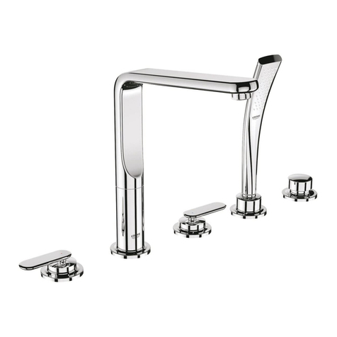
  9. Grohe Veris 19 343 User manual

Grohe Veris 19 343 User manual

English .....1
Français .....2
Español .....3
Design & Quality Engineering GROHE Germany
Veris
Veris
96.800.031/ÄM 214774/06.10
19 343
English .....1
Français .....1
Español .....2
I
19 343
*46 627
46 667
46 672
64 450
S.v.p remettre cette instruction à l'utilisateur de la robinetterie!
Entregue estas instrucciones al usario final de la grifería!
Please pass these instructions on to the end user of the fitting!
32 641
46 374
II
7
H
G
2,5mm
10mm
5
DEF
3
B
A
1
10mm
2
2,5mm
4
C1
C
6
G1
G
10mm
8
I
9
J
32mm
1
English
Français
Technical data
• Max. flow 8.3 L/min or 2.2 gpm/60 psi
Installation
Remove the fitting template, see fold-out page II, Fig. [1].
Flush piping system prior and after installation of faucet
thoroughly!
Flow rate limiter
This fitting is equipped with a flow rate limiter, permitting an
infinitely variable individual reduction in flow rate. The highest
possible flow rate is set at the factory before dispatch.
The use of flow rate limiters in combination with hydraulic
instantaneous heaters is not recommended.
For commissioning, see fold-out page II, Fig. [2].
Shut off hot and cold water supply.
I. Install escutcheon and lever, see Figs. [3], [4] and [5].
1.Attach cap (A) and (B), see Fig. [3].
2.Grease seal (C1) and push on escutcheon (C), see Fig. [4].
3.Attach lever (D) and fasten with set (E), see Fig. [5].
4.Attach cap (F).
If the escutcheon will not slide far enough onto the cap, you
must additionally install an extension (see replacement parts
fold-out page I, Prod. no.: 46 627 = 1").
II. Install spout, see Figs. [6] and [7].
1.Screw in 1/2" NPT-adaptor (G1), sold separately, to
concealed mixer housing, see Fig. [6].
2.Screw in connection nipple (G) using an 10mm allen
wrench.
3.Crosscut 1/2" NPT-adaptor in that way, that the installation
dimension is min 1 1/16"to max 1 1/8", see Fig. [7].
4.Tighten spout (H) from below using an 2,5mm allen wrench,
see Fig. [7].
Open hot and cold water supply and check connections
for leakage!
Check fitting for correct operation, see Fig. [8].
Maintenance
Inspect and clean all parts, replace as necessary and lubricate
with special grease.
Shut off hot and cold water supply.
I. Replacing the cartridge, see fold-out page II, Fig. [9].
Assemble in reverse order.
Observe the correct installation position!
When installing the cartridge, ensure that the seals are
correctly seated.
Install and tighten screw coupling (I).
II. Flow control (J),see fold-out page II, Fig. [9].
Assemble in reverse order.
Replacement parts,see fold-out page I (* = special
accessories).
Care
Instructions for care of this faucet will be found in the Limited
Warranty supplement.
Caractéristiques techniques
• Débit maxi. 8.3 l/min ou 2.2 g/min / 4.1 bar
Installation
Retirer le gabarit de montage, voir volet II, fig. [1].
Bien rincer les canalisations avant et après l’installation!
Limiteur de débit
Cette robinetterie est équipée d’un limiteur de débit. Celui-ci
permet une limitation individuelle et en continu du débit. Le
débit maximal est préréglé en usine.
L’utilisation du limiteur de débit est déconseillée avec des
chauffe-eau instantanés à commande hydraulique.
Pour l’activation voir volet II, fig. [2].
Couper l’alimentation en eau chaude et en eau froide.
I. Monter la rosace I et le levier, voir fig. [3], [4] et [5].
1.Insérer le capuchon (A) et (B), voir fig. [3].
2.Graisser le joint (C1) et insérer la rosace (C), voir fig. [4].
3.Emboîter le levier (D) et les fixer avec le kit (E), voir fig. [5].
4.Insérer le capuchon (F).
Si la rosace ne s’engage pas assez loin sur le capot, monter
une rallonge (voir Pièces de rechange, volet I,
réf. 46 627 = 25mm).
II. Montage du bec, voir fig. [6] et [7].
1.Visser le 1/2" NPT-adaptateur (G1), non fourni, au corps
encastré, voir fig. [6].
2.Visser la nipple de raccordement (G) à l'aide d'une clé
Allen de 10mm.
3.Couper à la bonne longueur la 1/2" NPT-adaptateur pour
obtenir une dimension de montage comprise entre 27mm
minimum et 29mm maximum, voir fig. [7].
4.Fixer le bec (H) par le bas à l’aide d’une clé Allen de 2,5mm,
voir fig. [7].
Ouvrir l’arrivée d’eau froide et d’eau chaude et vérifier
l’étanchéité des raccordements.
Vérifier le fonctionnement de la robinetterie, voir fig. [8].
Maintenance
Contrôler toutes les pièces, les nettoyer, les remplacer si
nécessaire et les graisser avec de la graisse spéciale pour
robinetterie.
Couper l’alimentation en eau chaude et en eau froide.
I. Remplacement de la cartouche, voir volet II, fig. [9].
Le montage s’effectue dans l’ordre inverse de la dépose.
Respecter la position de montage!
Contrôler le siège des joints lors du montage de la
cartouche.
Visser la bague filetée (I) et serrer jusqu’au blocage.
II. Mousseur (J), voir volet II, fig. [9].
Le montage s’effectue dans l’ordre inverse de la dépose.
Pièces de rechange, voir volet I (* = Accessoires spéciaux).
Entretien
Vous trouverez les instructions d'entretien de ce mitigeur dans
le supplément Garantie Limitée.
2
Español
Datos técnicos
• Caudal máx. 8.3 L/min o 2.2 gpm/60 psi
Instalación
Sacar el patrón de montaje, véase la página desplegable II,
fig. [1].
¡Purgar a fondo el sistema de tuberías antes y después
de la instalación!
Limitador de caudal
Esta grifería está equipada con un limitador de caudal. Gracias
a ello es posible una limitación individual del caudal sin
escalonamientos. El ajuste de fábrica corresponde al máximo
caudal posible.
Se recomienda no utilizar el limitador de caudal en
combinación con calentadores instantáneos con control
hidráulico.
Para la activación, véase la página desplegable II, fig. [2].
Cerrar las llaves de paso del agua fría y del agua caliente.
I. Montar el rosetón y la palanca, véanse las figuras [3], [4]
y[5].
1.Colocar la carcasa (A) y (B), véase la fig. [3].
2.Engrasar la junta (C1) y montar el rosetón (C), véase
la fig. [4].
3.Colocar la palanca (D) y fijar con el juego (E), véase la fig. [5].
4.Encajar la tapa (F).
Si al colocarlo el rosetón no deja sobresalir suficientemente la
carcasa habrá que montar además una prolongación (véase
piezas de recambio en la página desplegable I, núm. de
pedido: 46 627 = 1").
II. Montar el caño, véanse las figs. [6] y [7].
1.Enroscar el 1/2" NPT-adaptador (G1), no contenido en el
volumen suministro, a la cuerpo encontrable, véase
la fig. [6].
2.Enroscar el casquillo roscado de conexión (G) con una llave
Allen de 10mm.
3.Cortar a medida el 1/2" NPT-adaptador de modo que resulte
una cota de montaje de min. 1 1/16" hasta max. 1 1/8",
véase la fig. [7].
4.Fijar el caño (H) mediante una llave de macho hexagonal
de 2,5mm por la parte inferior, véase la fig. [7].
Abrir las llaves de paso del agua fría y del agua caliente
y comprobar la estanqueidad de las conexiones.
Comprobar el funcionamiento de la grifería, véase la fig. [8].
Mantenimiento
Verificar todas las piezas, limpiarlas, sustituirlas en caso de
necesidad y engrasarlas con grasa especial para griferías.
Cerrar las llaves de paso del agua fría y del agua caliente.
I. Sustituir el cartucho, véase la página desplegable II, fig. [9].
El montaje se efectúa en el orden inverso.
¡Atender a la posición de montaje!
Al montar el cartucho tener en cuenta el correcto asiento de
las juntas.
Enroscar la unión atornillada (I) y apretar firmemente.
II. Mousseur (J), véase la página desplegable II, fig. [9].
El montaje se efectúa en el orden inverso.
Piezas de recambio, véase la página desplegable I
(* = accesorios especiales).
Cuidados
En el suplemento Garantía Limitada encontrará las
instrucciones relativas al cuidado de esta batería.
Grohe Canada Inc.
1230 Lakeshore Road East
Mississauga, Ontario
Canada, L5E 1E9
Technical Services
Services Techniques
Phone/Tél: 905/271-2929
Fax/Télécopieur: 905/271-9494
Grohe America Inc.
241 Covington Drive
Bloomingdale, IL
60108
U.S.A.
Technical Services
Phone: 630/582-7711
Fax: 630/582-7722
www.grohe.com

Other Grohe Plumbing Product manuals

Grohe 27 864 User manual

Grohe

Grohe 27 864 User manual

Grohe Grohtherm Cube Quick start guide

Grohe

Grohe Grohtherm Cube Quick start guide

Grohe Sentosa 34 686 User manual

Grohe

Grohe Sentosa 34 686 User manual

Grohe Grohtherm F 35 035 User manual

Grohe

Grohe Grohtherm F 35 035 User manual

Grohe BAULOOP 20 225 User manual

Grohe

Grohe BAULOOP 20 225 User manual

Grohe Essence 33 532 User manual

Grohe

Grohe Essence 33 532 User manual

Grohe ESSENCE 20 297 User manual

Grohe

Grohe ESSENCE 20 297 User manual

Grohe Ondus User manual

Grohe

Grohe Ondus User manual

Grohe Blue 31 087 User manual

Grohe

Grohe Blue 31 087 User manual

Grohe F-digital User manual

Grohe

Grohe F-digital User manual

Grohe GROHTHERM XL 35 085 User manual

Grohe

Grohe GROHTHERM XL 35 085 User manual

Grohe Lineare 19 409 User manual

Grohe

Grohe Lineare 19 409 User manual

Grohe Precision Trend 34 227 User manual

Grohe

Grohe Precision Trend 34 227 User manual

Grohe EUROSTYLE 23 577 User manual

Grohe

Grohe EUROSTYLE 23 577 User manual

Grohe GROHTHERM F User manual

Grohe

Grohe GROHTHERM F User manual

Grohe Ondus User manual

Grohe

Grohe Ondus User manual

Grohe 26 075 User manual

Grohe

Grohe 26 075 User manual

Grohe Euroeco Cosmopolitan E 36 269 User manual

Grohe

Grohe Euroeco Cosmopolitan E 36 269 User manual

Grohe 34487000 User manual

Grohe

Grohe 34487000 User manual

Grohe MINTA TOUCH 30 218 User manual

Grohe

Grohe MINTA TOUCH 30 218 User manual

Grohe Bus Home Connected 31 545 User manual

Grohe

Grohe Bus Home Connected 31 545 User manual

Grohe Atrio 21 019 User manual

Grohe

Grohe Atrio 21 019 User manual

Grohe Tectron 37 321 User manual

Grohe

Grohe Tectron 37 321 User manual

Grohe Eurodisc Cosmopolitan 19 573 User manual

Grohe

Grohe Eurodisc Cosmopolitan 19 573 User manual

Popular Plumbing Product manuals by other brands

Hans Grohe Duo Plus 12020000 manual

Hans Grohe

Hans Grohe Duo Plus 12020000 manual

Durasage DIF-5000 User guide and instruction manual

Durasage

Durasage DIF-5000 User guide and instruction manual

JADO Borma 814 999 Series installation instructions

JADO

JADO Borma 814 999 Series installation instructions

Geberit Monolith Plus user manual

Geberit

Geberit Monolith Plus user manual

Crosswater UNION US-UN800 installation instructions

Crosswater

Crosswater UNION US-UN800 installation instructions

Jacuzzi Aura Uno instruction manual

Jacuzzi

Jacuzzi Aura Uno instruction manual

Project Source F4510018CP manual

Project Source

Project Source F4510018CP manual

Hans Grohe ShowerSelect S 15553 Series Instructions for use/assembly instructions

Hans Grohe

Hans Grohe ShowerSelect S 15553 Series Instructions for use/assembly instructions

Omnires Y1233GL Installation and Maintenance

Omnires

Omnires Y1233GL Installation and Maintenance

Hans Grohe Talis M52 220 2jet 73863 Series Instructions for use/assembly instructions

Hans Grohe

Hans Grohe Talis M52 220 2jet 73863 Series Instructions for use/assembly instructions

Toto TLE0150 Series instruction manual

Toto

Toto TLE0150 Series instruction manual

Chicago Faucets Plumbing Product installation instructions

Chicago Faucets

Chicago Faucets Plumbing Product installation instructions

Axor Uno2 38040XX1 Installation instructions / warranty

Axor

Axor Uno2 38040XX1 Installation instructions / warranty

Axor Starck 10010000 Instructions for use/assembly instructions

Axor

Axor Starck 10010000 Instructions for use/assembly instructions

Bristan Jute JU BF C Fitting Instructions & Contents List

Bristan

Bristan Jute JU BF C Fitting Instructions & Contents List

DURAVIT 033955 Series Template and mounting instructions

DURAVIT

DURAVIT 033955 Series Template and mounting instructions

Glacier bay 67257W-0001 Installation and care guide

Glacier bay

Glacier bay 67257W-0001 Installation and care guide

Moen FINA S3600 installation guide

Moen

Moen FINA S3600 installation guide

manuals.online logo
manuals.online logoBrands
  • About & Mission
  • Contact us
  • Privacy Policy
  • Terms and Conditions

Copyright 2025 Manuals.Online. All Rights Reserved.