Groth 8110 Owner's manual

INSTALLATION, OPERATION AND MAINTENANCE
GROTH MODEL 8110
10" & 12" BACK PRESSURE CHECK VALVE
IOM 8110L.0
Septe ber, 1999

1
GENERAL:
The Groth Model 8110 is a swing check
valve utilizing a single disk which allows
flow in one direction. In the event that
the downstream pressure is higher than
the inlet pressure, the higher ack
pressure will hold the disk in the closed
position. If u le tight shut-off is
required, an elastomer seat must e
specified.
INSTALLATION:
The Model 8110 must e installed
upright with its axis horizontal to achieve
the rated flow capacity with minimal
pressure drop. A tag on the valve ody
indicates flow direction and the upright
position. Proper orientation is also
important so the drain ports can e used
to remove condensation from the
housings.
Align and install adjacent piping so that
no undue stress is imposed on the valve
ody. Refer to ta les 1 & 2 for gasket
and olt torque recommendations.
Excessive olt torque may damage
aluminum flanges.
Table 1
Body Flange Gasket Di ensions
150#
ANSI
Flange
O.D. I.D. B.C. Hole Qty
10” RF 13.38” 10.80” --- --- ---
12” RF 16.12” 12.80” --- --- ---
10” FF 16.00” 10.00” 14.25” 1.00” 12
12” FF 19.00” 12.00” 17.00” 1.00” 12
* RF = Raised Face , FF = Flat Face
Table 2
Reco ended Mini u Torque Values
Size Qty
Holes
Bolt
(UNC)
Torque (lb-ft)
RF FF
10” 12 7/ 8” - 9 75 138
12” 12 7/ 8” - 9 93 179
*Note : Torque values are ased on gasket factors
m = 3.5, y = 4000 psi, operating pressure = 30 psi
Note: Flat face flanges require full
flange gaskets.
OPERATION:
The operation of the Model 8110 is fully
automatic. There are no adjustments
required.
MAINTENANCE:
The check valve does not require
routine lu rication. If servicing or
disassem ly is required, the valve must
e removed from the line. Num ers in[
] in this section refer to the item
identification in figure 1.
SAFETY WARNINGS
Properly block and vent the line before
removin the valve. Observe all plant
procedures and Material Safety Data Sheet
recommendations for the products in the
system when removin and disassemblin
the valve.
Support the valve vertically on a ench
with the flow direction upward. Remove
the studs and hex nuts [2 & 3] and lift
the downstream housing [1] from the
valve. Remove the gasket [7] and the
seat/disk su -assem ly.
Inspect the seat [6] and the disk [5].
Both seating surfaces must e clean
and flat. If it is necessary to lap the
seat, remove the olts [9], nuts [10] and
teflon washer [11] that attach the swing
assem ly. Clean the valve and replace
all worn or damaged components efore
reassem ly. Check the disk and link to
e sure they are free to swing and that
seating is uniform. Align seat ring with
locating pins in upstream housing.
Reassem le in the reverse order of
disassem ly.

2
Figure 1 – Assem ly Drawing
BILL OF MATERIALS
MATERIAL
ITEM # DESCRIPTION ALUMINUM CS SS
1 HOUSING ALUMINUM CS 316SS
2 STUD SS SS SS
3 HEX NUT SS SS SS
4 HEX PLUG 316SS 316SS 316SS
5 DISK ALUMINUM 316SS 316SS
6 SEAT PLATE 316SS 316SS 316SS
7 GASKET NON-ASBESTOS FIBER √
8 BRACKET, PIVOT ALUMINUM 316SS 316SS
9 HEX BOLT SS SS 316SS
10 HEX NUT SS SS 316SS
11 FLAT WASHER TEFLON √
12 LINK ALUMINUM 316SS 316SS
13 PIN, PIVOT SS SS 316SS
14 ARM, PIVOT ALUMINUM 316SS 316SS
3
Recommended replacement part. See
adjacent ta le for Groth part num er.
Please specify model num er, size, and
serial num er when ordering replacement
parts.
Item Size Replacement P/N
7 10" 80018100
7 12" 80018120
11 All 87422003
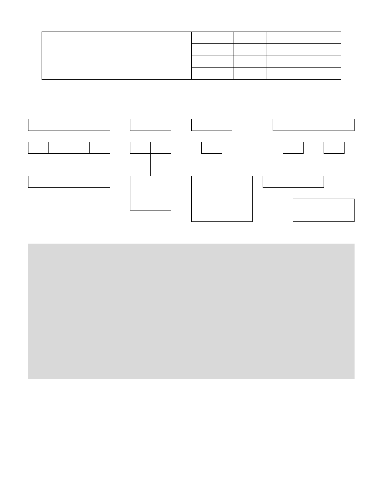
The nameplate on the Groth Model 8110 Swing Check Valve contains the model num er, serial
num er and flow capacity. The model num er contains additional information a out materials
of construction and options. The following chart will assist in relating the model num er to the
specifications of your check valve:
MODEL # SIZE MATERIAL OPTIONS
−
−−
− −
−−
− −
−−
−
8110 10"
OR
12"
1 = ALUMINUM
3 = CS
5 = 316SS
Z = SPECIAL
F=FLANGED
Z = SPECIAL
O = NO SPECIAL
Example: 8110-12-1-FO indicates a 12" Model 8110, aluminum ody, flanged with no special options.
PRODUCT LIMITED WARRANTY
A. Seller warrants that products which are manufactured y Seller,
are manufactured in accordance with pu lished specifications
and free from defects in material and/or workmanship for a
period of (12) twelve months. Seller, at its option, will repair or
replace any product returned intact to the factory, transportation
charges prepaid, which Seller, upon inspection shall determine to
e defective in material and/or workmanship. The foregoing
shall constitute the sole remedy for any reach of Seller's
warranty.
B. THERE ARE NO UNDERSTANDINGS, AGREEMENTS,
REPRESENTATIONS, OR WARRANTIES, EXPRESS OR
IMPLIED (INCLUDING MERCHANTABILITY OR FITNESS FOR
A PARTICULAR PURPOSE REGARDING PRODUCTS)
UNLESS SPECIFIED IN THE SALES CONTRACT. THIS
CONTRACT STATES THE ENTIRE OBLIGATION OF SELLER.
Seller makes no warranties, either express or implied, except as
provided herein, including without limitation thereof, warranties
as to marketa ility, merchanta ility, for a particular purpose or
use, or against infringement of any patent of products. In no
event shall Seller e lia le for any direct, incidental or
consequential damages of any nature, or losses or expenses
resulting from any defective new product or the use of any such
product, including any damages for loss of time, inconvenience,
or loss of use of any such product.
C. The original Manufacturer shall e solely responsi le for the
design, development, supply, production, and performance of its
products hereunder, and the protection of its trade name or
names, if any. It assumes no responsi ility, for product modified
or changed in any way y its agent or customer. Any such
modifications or changes to products sold y Seller hereunder
shall make the product limited warranty null and void.
D. The Manufacturer shall e under no o ligation to manufacture,
sell, or supply, or to continue to manufacture, sell or supply any
of the Products.
Other Groth Control Unit manuals


Popular Control Unit manuals by other brands

Festo
Festo Compact Performance CP-FB6-E Brief description

Elo TouchSystems
Elo TouchSystems DMS-SA19P-EXTME Quick installation guide

JS Automation
JS Automation MPC3034A user manual

JAUDT
JAUDT SW GII 6406 Series Translation of the original operating instructions

Spektrum
Spektrum Air Module System manual

BOC Edwards
BOC Edwards Q Series instruction manual

KHADAS
KHADAS BT Magic quick start

Etherma
Etherma eNEXHO-IL Assembly and operating instructions

PMFoundations
PMFoundations Attenuverter Assembly guide

GEA
GEA VARIVENT Operating instruction

Walther Systemtechnik
Walther Systemtechnik VMS-05 Assembly instructions

Altronix
Altronix LINQ8PD Installation and programming manual


