Grouser Products Ag Pro Plus User manual

Date 2-7-2017
PN: 63-19645-A
Ag Pro Plus/Ag Pro SS
Versatile 350-550 Wheeled
Undercarriage Installation Instructions
Purchase Date
Serial Number
Model Number
Tractor Model
Dealer
Serial No: 10204178-10204856

2
Description Page
To The Owner & Torque Specications 2
Safety Precautions & Unpacking Components 3
Undercarriage Installation Instructions 4-5
Maintenance & Assembling Lift Components 5
Undercarriage Assembly Diagram 6-7
Hose Routing 8
Tow Cable Components 9
Notes 10-11
Contact Us, Improvements, & Warranty 12
Contents
To The Owner
This manual contains information concerning the operation, adjustment, and maintenance of the Ag Pro Plus dozer
system. You have purchased dependable, long lasting equipment, but only by proper care and operation can you
expect to receive the performance and long service built into our products. Please have all operators read this manual
carefully and keep the manual available for ready reference. If you have any questions or concerns, contact Grouser
Products.
Torque Specications
All bolts should be tightened to the specications that are stated. If specications are not stated, follow torque charts
below.
Torque - Dry (ft–lbs)
SAE Grade 5 SAE Grade 8
Size UNC UNF UNC UNF
5/16 19 20 29 31
3/8 33 36 47 51
7/16 54 58 78 85
1/2 78 85 119 129
9/16 114 124 169 184
5/8 154 167 230 250
3/4 257 280 380 414
7/8 382 416 600 654
1 587 639 903 984
Torque - Dry (ft-lbs)
Size Grade 10.9
M18 x 2.00 236
M20 x 2.50 432
M22 x 2.50 394
M24 x 3.00 570

3
Safety Precautions
A careful operator is the best operator. Most accidents can be avoided by observing certain precautions. To help
prevent accidents, read and take the following precautions before operating this equipment. In addition to these
precautions, please follow all safety and operational instructions supply by your tractor manufacturer.
The Dozer:
1. The Ag Pro Plus Dozer should be operated only by those who are responsible and instructed to do so.
2. Read the owner’s manual carefully before using this equipment. Lack of operating knowledge can lead to
accidents.
3. Keep the dozer maintained and in good condition to ensure your safety.
4. Make sure the area around you is clear of people before moving any equipment.
5. Do not modify or permit anyone else to modify or alter the equipment and its components without rst consulting
Grouser Products.
Servicing the Dozer:
1. Read and follow all safety instructions provided by the tractor manufacturer.
2. Always use proper personal safety gear when performing maintenance on equipment.
3. Before servicing, relieve hydraulic pressure, stop engine and fully engage parking brake.
4. Escaping hydraulic uid under pressure can penetrate skin causing serious injury. If uid is injected into skin,
obtain medical attention immediately.
– DO NOT use your hand to check for leaks. Use a piece of cardboard or paper to search for leaks.
– Stop the engine and relieve trapped hydraulic pressure before connecting or disconnecting lines.
– Tighten all connections before starting the engine or pressurizing lines.
Storing the Dozer:
1. Thoroughly clean the dozer before storage. Use paint where necessary to prevent rust.
2. Check for worn or damaged parts. Install new parts as required.
3. Lubricate all pins and joints.
Unpacking Components
Unstrap and remove any components that are attached for shipping. If any components are missing, call Grouser.

4
Note: Add shims between the undercarriage and
the tractor frame to reduce any gap if necessary.
Use shims until there is a gap of 1/16” or less on
the front. See attached diagram for the proper
location and orientation of each shim. Don’t put all
the shims on one side of the undercarriage.
Caution:
• Always use caution when working around any
equipment.
• Always wear safety glasses.
• Follow tractor manufacturer’s safety guidelines
when installing this product.
• Use paint where necessary to prevent rust.
• Do not modify or permit anyone else to modify
or alter the equipment and its components
without rst consulting Grouser Products.
Note:
• When installing hardware, only nger tighten
until all hardware is in place.
• A full diagram of the assembly with the full list
of parts is on pages 6-7.
• Tractor frame not shown in some diagrams for
clarity.
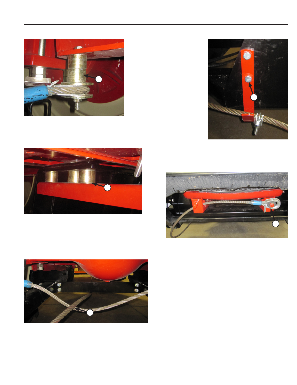
• Unstrap and remove any components that are
attached for shipping.
• Read all instructions prior to performing
installation.
Undercarriage Installation
1. Remove existing toolboxes, front weights, and tow
cable holder if equipped. Tow cable holder can be
reinstalled later with the undercarriage.
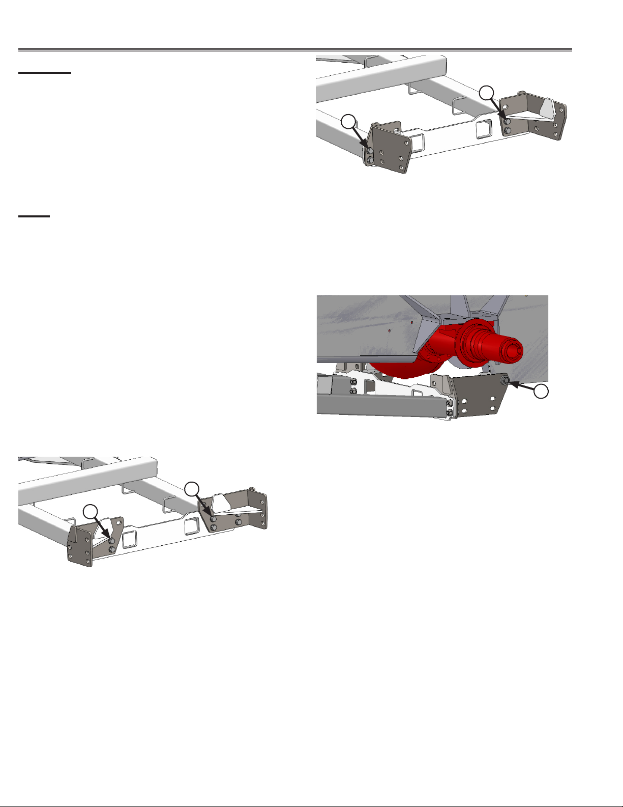
1
5. Attach the rear brackets to the rear of the
undercarriage with 8 - 3/4” x 2” bolts, 16 - 3/4” washers,
and 8 - 3/4” nuts (1).
2. Remove the front cover on the undercarriage if
necessary.
3. For tractor models 450-550, continue with Step #5.
7. Attach the rear brackets to the rear of the
undercarriage with 8 - 3/4” x 2” bolts, 16 - 3/4” washers,
and 8 - 3/4” nuts (2).
6. Continue with Step #8.
1
2
2
Note: The left bracket (long plate against
undercarriage) attaches on the left side of the
undercarriage and the right bracket on the right
side.
4. For tractor models 350-400, continue with Step #7.
Note: The right bracket (short plate against
undercarriage) attaches on the left side of the
undercarriage and the left bracket on the right side.
8. Position the undercarriage under the tractor and
center on the frame of the tractor.
9. Raise the rear of the undercarriage and attach the
rear brackets to the frame of the tractor behind the
front axle with 2 - 20mm x 70mm bolts, 4 - 3/4” ID thick
washers and 2 - 20mm nuts (3).
3
Note: The above photo shows the brackets
installed on a narrow frame but the installation is
the same for the wide frame.
10. Raise the front of the undercarriage until the holes
line up with the holes on the tractor.

5
4
11. Install 8 - 20mm x 70mm bolts, 8 - 3/4” ID thick
washers, 8 - 3/4” washers and 8 - 20mm nuts into the
side holes of the undercarriage, shims if necessary,
and the tractor frame (4).
12. At the front of the undercarriage, install
6 - 20mm x 70mm bolts, 12 - 3/4” washers and 6 - 20mm
nuts into the front vertical holes of the undercarriage
and the tractor frame (5). The bolt has to be inserted
from the bottom.
Note: If the tow cable bracket was equipped,
reinstall the bracket when installing the front 6
vertical bolts. See Page 9 for more hardware and
installation information.
13. Push the undercarriage back until the rear brackets
are pushing against the tractor frame.
14. Torque the rear 20mm bolts to 432 ft-lbs, the 3/4”
bolts to 257 ft-lbs, the front vertical 20mm bolts to 432
ft-lbs, and then the side 20mm bolts to 432 ft-lbs.
15. If the front cover was removed, reattach with the
original hardware.
1. After rst 8 hours of use, re-torque all bolts.
2. Check all fasteners regularly to ensure proper operation of equipment.
3. Inspect all equipment for existing or potential damages every 10 hours or less.
Maintenance
Assembling Lift Components
Refer to the Ag Pro Plus Owner’s Manual & Parts Book for instructions on how to assemble the lift components.
5
4. Make sure all non-rotating pins are secured properly.
5. Lubricate all joints with high quality grease.
Note: Installer is responsible to route hoses in a practical manner. The hoses need to be routed away from
sharp and moving objects and need to be secure. Install all hoses when assembling the lift system in the
Owner’s Manual and Parts Book. Refer to Page 8 for some hose routing pictures.

6
DWG. NO.: 19645-A
Bracket Orientation
Narrow Frame (Versatile 350-400)
6
5
9
8
Note: Narrow frame uses the left rear bracket on the right side of the undercarriage
and the right bracket on the left side of the undercarriage as shown in the diagram below.
4
15
1
15
18
6
5
17
14
12
2
14
1
15
17
19 15
10
14
16
11
1
3
14
Wide Frame (Versatile 450-550)
Bracket Orientation
16
13
7
ITEM NO. QTY. PART NO DESCRIPTION
1 16 16-1876 20mm x 2.5mm x 70mm Gr. 10.9 Hex Bolt
2 4 16-20124 1/2" x 1" Hex Bolt Gr.5 NC
3 4 16-20125 1/2" x 1-1/4" Hex Bolt Gr 5 NC
4 8 16-20218 3/4" X 2" Hex Bolt Gr.5 NC
5 1 18-15945-L Adapter Bracket
6 1 18-15945-R Adapter Bracket
7 2 27-18880 Ag Pro Plus Decal
8 1 27-18887 Grouser Name Plate Decal
9 1 27-9506 Serial Tag Decal
10 4 44-15966 Versatile T4 Shim Plate (.125")
11 8 44-15967 Versatile T4 Shim Plate (.06")
12 1 44-19646 Plate, Hose Cover
13 1 54-19645 Undercarriage Weld, Ag Pro Plus
14 15 57-20744 1/2" Flat Washer
15 36 57-20757 3/4" Flat Washer - 1-1/2" OD
16 12 57-3680 3/4" ID x 2.00 OD x .375" Heavy Washer CZ Plated
17 7 70-20604 1/2" Center Lock Hex Nut
18 8 70-20607 3/4" Center Lock Hex Nut NC
19 16 70-20872-10 20mm Hex Nut 2.5 Pitch Class 10 Zinc

7
DWG. NO.: 19645-A
Bracket Orientation
Narrow Frame (Versatile 350-400)
6
5
9
8
Note: Narrow frame uses the left rear bracket on the right side of the undercarriage
and the right bracket on the left side of the undercarriage as shown in the diagram below.
4
15
1
15
18
6
5
17
14
12
2
14
1
15
17
19 15
10
14
16
11
1
3
14
Wide Frame (Versatile 450-550)
Bracket Orientation
16
13
7
ITEM NO. QTY. PART NO DESCRIPTION
1 16 16-1876 20mm x 2.5mm x 70mm Gr. 10.9 Hex Bolt
2 4 16-20124 1/2" x 1" Hex Bolt Gr.5 NC
3 4 16-20125 1/2" x 1-1/4" Hex Bolt Gr 5 NC
4 8 16-20218 3/4" X 2" Hex Bolt Gr.5 NC
5 1 18-15945-L Adapter Bracket
6 1 18-15945-R Adapter Bracket
7 2 27-18880 Ag Pro Plus Decal
8 1 27-18887 Grouser Name Plate Decal
9 1 27-9506 Serial Tag Decal
10 4 44-15966 Versatile T4 Shim Plate (.125")
11 8 44-15967 Versatile T4 Shim Plate (.06")
12 1 44-19646 Plate, Hose Cover
13 1 54-19645 Undercarriage Weld, Ag Pro Plus
14 15 57-20744 1/2" Flat Washer
15 36 57-20757 3/4" Flat Washer - 1-1/2" OD
16 12 57-3680 3/4" ID x 2.00 OD x .375" Heavy Washer CZ Plated
17 7 70-20604 1/2" Center Lock Hex Nut
18 8 70-20607 3/4" Center Lock Hex Nut NC
19 16 70-20872-10 20mm Hex Nut 2.5 Pitch Class 10 Zinc

8
1. Route hoses through the hose loops on the
undercarriage.
4. Use zip ties to attach hoses, where necessary, to
avoid rubbing and pinch areas.
NOTE: The quantity of hoses may vary depending
on blade system.
NOTE: If blade system has Dual Remote
Hydraulic Angle, verify that the 35” hose is
used and installed correctly. Refer to hydraulic
schematic in the Owner’s Manual & Parts Book
if necessary.
Left Angle Retract
Lift - Orange
Angle - Yellow
Tilt Left
35" Hose
to Yellow at Rear of Tractor
Left Angle Extend
Lift - Orange
SCV Group C
Angle Cylinder Rod - Tee Fitting
Tilt Cylinder Rod
SCV Group A
Lift Cylinder Base
Angle - Red
Left Angle Cylinder Base
Lift Up
SCV Group B
Lift Cylinder Rod
Tilt - Green
Right Angle Retract
SCV Group D
Tilt Cylinder Base
Lift Down
Tilt - Green
Hoses Not Drawn To Scale
Tilt Right
Angle - Red at Top Arm - Change
Angle - Red
Right Angle Extend
Right Angle Cylinder Base
Hose Routing
2. After routing the hoses through the undercarriage,
route in the same location as the tractor’s hoses (1).
Replace zip ties if you run the hoses in the tractor’s
original hose cordura.
3. Exit the rear frame at the center of the frame as
shown in the picture (2).
5. After installing the male couplers, plug each set into
a set of rear SCV’s (3).
1
2
3

9
Tow Cable Installation
1. Add 2 spacers in between the cable holder and
the tractor frame by the front tires. Use a 5/8” x 6”
bolt (PN: 16-20200), 2 - 5/8” washers
(PN: 57-20746) and a 5/8” top lock nut
(PN: 70-20646) on each side (1).
2. Install the front cable support bracket at the front
of the undercarriage. Install with 3 spacers on each
side in between the undercarriage and the bracket.
Use 3 - 20mm x 120mm (PN: 16-2489) to install the
bracket and undercarriage. Use the same washers
and nuts that were used in the mounting instructions
on Page 5 (2).
3. Route the cable underneath the undercarriage, then
over the cable support and under the undercarriage on
the right side (3).
4. Install the original bracket to the side of
the undercarriage with 2 - 3/4” x 2” bolts
(PN: 16-20218) and 2 - 3/4” nuts
(PN: 70-20607). Cable clamp is installed in
Step #6.
5. Finish routing the cable under the lift frame and up
over the cable bracket. Attach to the bracket with the
original hardware (4).
6. Pull the cable so there is some slack at the front
under the lift frame as shown in the picture above. Then
put a cable clamp up by the side bracket as shown in
the picture from Step #4 to keep the cable in place.
Note: Your undercarriage may vary slightly from the one shown in the pictures below, but the same
installation procedure will be compatible.
1
2
3
4
4

10
Notes

11
Notes

12
Warranty
Contact Us
Improvements
Grouser Products Inc. is continually striving to improve its products. We reserve the right to change
prices, specication, or equipment at any time without notice. We also reserve the right to make
improvements or changes when it becomes practical and possible to do so without incurring any
obligation to make changes or additions to the equipment sold previously.
As always, if you have any questions about your Ag Pro Plus undercarriage or other products made
by Grouser, feel free to contact us.
Grouser Products
755 2nd Ave NW - West Fargo, ND 58078
Phone: 1-800-747-6182
Fax: 1-701-282-8131
E-mail: grouser@grouser.com
Website: www.grouser.com
Grouser Products warrants to the original purchaser of each item that the product be free from
defects in material and workmanship under normal use and service for a period of two years from
date of original retail delivery. If such equipment is found to be defective within two years, it is the
obligation of Grouser Products under this warranty to repair or replace (exclusive of the cost of labor
and transportation), any equipment or parts, in the judgment of Grouser Products to be defective in
material or workmanship.
All equipment or parts claimed to be defective in material or workmanship must be made available
for inspection at the place of business of a dealer authorized to handle the equipment covered by this
warranty, or, upon request by Grouser Products, shipped to the Grouser Products factory in West Fargo,
North Dakota. Grouser Products shall have no obligation to bear the cost of labor or transportation in
connection with replacement or repair of any such defective parts in the setup process.
This warranty covers only defects in material and workmanship. It does not cover depreciation
or damage caused by normal wear, accident, improper assembly, improper adjustments, improper
maintenance including lack of proper lubrication, or improper use. Therefore, Grouser Products liability
under this warranty shall not be effective or actionable unless the equipment is assembled, maintained
and operated in accordance with the operating instructions accompanying the equipment. Grouser
Products shall have no liability if the equipment has been altered or reworked without the written
authorization of Grouser Products.
Grouser Products’ parts, which are furnished under this warranty and properly installed, shall
be warranted to the same extent as the original parts under this warranty if, and only if, such parts are
found to be defective within the original warranty period covering the original equipment.
Other manuals for Ag Pro Plus
3
This manual suits for next models
1
Table of contents
Other Grouser Products Farm Equipment manuals

Grouser Products
Grouser Products Ag Pro 12-20 User manual

Grouser Products
Grouser Products Ag Pro Plus HD User manual

Grouser Products
Grouser Products Ag Pro 3-5 User manual

Grouser Products
Grouser Products Ag Pro Plus User manual

Grouser Products
Grouser Products FH-400 User manual

Grouser Products
Grouser Products 770HD Steiger T4B Wheeled User manual

Grouser Products
Grouser Products Ag Pro 660HD User manual