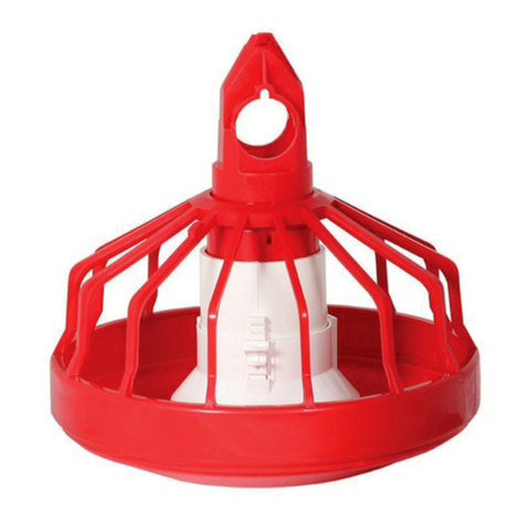
Cumberland Hi-Lo User manual

PNEG-250
Hi-Lo and PRO-1 Pan Feeders
(For parts, refer to PNEG-250-PM)
Installation and Operation Manual
PNEG-250
Version: 7.5
Date: 06-09-17

2PNEG-250 Hi-Lo and PRO-1 Pan Feeders
All information, illustrations, photos and specifications in this manual are based on the latest
information available at the time of publication. The right is reserved to make changes at any
time without notice.

Table of Contents
PNEG-250 Hi-Lo and PRO-1 Pan Feeders 3
Contents
Chapter 1 Introduction ..........................................................................................................................................4
Chapter 2 Safety .....................................................................................................................................................5
Safety Guidelines ...................................................................................................................................5
Cautionary Symbols Definitions .............................................................................................................6
Safety Cautions ......................................................................................................................................7
Safety Sign-Off Sheet ..........................................................................................................................10
Chapter 3 Decals ..................................................................................................................................................11
Safety Decals and Placement ..............................................................................................................11
Chapter 4 Calculating Weight .............................................................................................................................14
Calculating Weight of Feedline at Each Suspension Point ..................................................................14
Determine Weight of Entire System .....................................................................................................14
Chapter 5 Capacities and Specifications ...........................................................................................................15
Chapter 6 Planning the System ..........................................................................................................................17
House Layout .......................................................................................................................................17
Chapter 7 Installation ..........................................................................................................................................19
Installation Sequence ...........................................................................................................................19
Feeder Assembly .................................................................................................................................19
“E” Feeder Assembly Instructions ........................................................................................................29
Tubing Assembly ..................................................................................................................................34
Feeder Assembly Rooster Feeder .......................................................................................................38
Program Chart ......................................................................................................................................43
Drive Unit/Control Pan Assembly .........................................................................................................49
Control Pan Assembly ..........................................................................................................................52
Auger Installation .................................................................................................................................62
Hopper Assembly .................................................................................................................................66
650 Lbs. Hopper Scale .........................................................................................................................67
Anti-Roost Wire ....................................................................................................................................69
Hopper Level Control Switch ................................................................................................................71
Winching ..............................................................................................................................................72
Power Winch Instructions .....................................................................................................................79
Chapter 8 Troubleshooting .................................................................................................................................85
Chapter 9 Wiring Diagrams .................................................................................................................................87
Rooster/Power Winch Wiring Diagram .................................................................................................87
Microswitch End Control 220V, 1 Phase (7101483) ............................................................................88
Microswitch End Control 3 Phase (07101483-3) ..................................................................................89
Microswitch Center Control 220V, 1 Phase (7101540) ........................................................................90
Microswitch End and Center Control ....................................................................................................91
End Control Box, i-Plus3 (C2000535) ..................................................................................................92
Center Control Box, i-Plus3 (C2000563) ..............................................................................................93
End Control Box, i-Plus3 3 Phase (C2000590) ....................................................................................94
i-Plus3 End and Center Control ...........................................................................................................95
LED Light and i-Plus3 End Control ......................................................................................................96
Proximity Switch End Control 220V, 1 Phase (7100842) .....................................................................97
Proximity Switch Center Control 220V, 1 Phase (C2000528) ..............................................................98
Proximity End and Center Control ........................................................................................................99
Spinner End Control 110V, 1 Phase (7100614) .................................................................................100
Spinner End Control 220V, 1 Phase (7100211) .................................................................................101
Spinner Center Control 110V-220V, 1 Phase (C2000306) ................................................................102
Spinner Center Control 220V (7100407) ............................................................................................103
Spinner End and Center Control ........................................................................................................104
Chapter 10 Warranty ..........................................................................................................................................105

4PNEG-250 Hi-Lo and PRO-1 Pan Feeders
1. Introduction
Cumberland’s Hi-Lo Pan Feeder is a revolutionary two-stage feeder bringing together features and
advantages of other systems, and introducing original and effective solutions to some persistent problems
and concerns.
The Pan Feeder System is designed to convey granular or powdered poultry feed from external feed bins
into the poultry house. It utilizes a screw auger to supply feed to Pan Feeders. The auger and pans are
located in the building, and the birds feed directly from it.
Feed is delivered from the feed bin via a feed conveying system such as the Flex-Flo, which is designed
to run in conjunction with the Pan Feeder.
For clean out purposes, the Pan Feeder may be raised up to a high level using a winching system.
This allows clear access to the building.
The Hi-Lo Pan Feeder System is designed for simple installation, though it is recommended that a
specialist be consulted with for the electrical wiring installation.
Because the first 7-10 days of a broiler’s life arecritical, the Hi-Lo Pan Feeder rests on the house floor and
presents a lip height of 2.1" (5.334 cm) the average height of traditional “feeder lids”. Young chicks can
easily get in and out of the pan and are eating out of the pan from day one. And because the pan need
not be flooded, they get fresher feed. The Hi-Lo Pan Feeder provides an excellent start for young birds.
Asthe birds grow, andthefeed line is raised,theHi-LoPan Feeder expandsintothemore easily managed
3.5" (8.89 cm) deep pan.
For larger birds, the higher wall and feed saver lip (wider than the lip currently on the standard grilled
feeder) prevent waste from raking and eliminate bill-out. The additional height also compels the birds to
eat nearer the edge of the pan, assuring a more even “first in, first out” utilization of feed (which both saves
feed and maintains freshness).
Cumberland values customer feedback and suggestions to help determine what features and functions
most enhance the efficiency and profitability of operations. Many of Cumberland’s design and
manufacturing advantages, including the Hi-Lo Pan Feeder, have been direct responses to customer
comments and suggestions.
Please send any questions, suggestions or comments to Cumberland at the following address:
Contact:
Cumberland
1004 E. Illinois St.
Assumption, IL. 62510
Phone: 1-217-226-4421

PNEG-250 Hi-Lo and PRO-1 Pan Feeders 5
2. Safety
Safety Guidelines
Safety guidelines are general-to-specific safety rules that must be followed at all times. This manual is
written to help you understand safe operating procedures and problems that can be encountered by the
operator and other personnel when using this equipment. Save these safety guidelines for future
reference.
As owner or operator, you are responsible for understanding the requirements, hazards, and precautions
that exist and to inform others as required. Unqualified persons must stay out of the work area at all times.
Alterations must not be made to the equipment. Alterations can produce dangerous situations resulting in
SERIOUS INJURY or DEATH.
This equipment must be installed in accordance with the current installation codes and applicable
regulations,whichmustbe carefully followed inallcases. Authorities havingjurisdictionmust be consulted
before installations are made.
When necessary, you must consider the installation location relative to electrical, fuel and water utilities.
Personnel operating or working around equipment must read this manual. This manual must be delivered
with equipment to its owner. Failure to read this manual and its safety instructions is a misuse of the
equipment. ST-0001-3

2. Safety
6PNEG-250 Hi-Lo and PRO-1 Pan Feeders
Cautionary Symbols Definitions
Cautionary symbols appear in this manual and on product decals. The symbols alert the user of potential
safety hazards, prohibited activities and mandatory actions. To help you recognize this information, we
use the symbols that are defined below.
NOTICE
DANGER
WARNING
CAUTION
This symbol indicates an imminently hazardous situation
which, if not avoided, will result in serious injury or death.
This symbol indicates a potentially hazardous situation
which, if not avoided, can result in serious injury or death.
This symbol indicates a potentially hazardous situation which,
if not avoided, can result in minor or moderate injury.
This symbol is used to address practices not related to
personal injury.
This symbol indicates a general hazard.
This symbol indicates a prohibited activity.
This symbol indicates a mandatory action.
ST-0005-2

2. Safety
PNEG-250 Hi-Lo and PRO-1 Pan Feeders 7
Safety Cautions
Use Personal Protective Equipment
Eye
Protection
Hearing
Protection
Hand
Protection
Head
Protection
Respiratory
Protection Foot
Protection
Fall
Protection
• Use appropriate personal protective equipment:
• Wear clothing appropriate to the job.
• Remove all jewelry.
• Tie long hair up and back.
ST-0004-1
Follow Safety Instructions
• Carefully read all safety messages in this manual and
safety signs on your machine. Keep signs in good
condition. Replace missing or damaged safety signs. Be
sure new equipment components and repair parts include
the current safety signs. Replacement safety signs are
available from the manufacturer.
• Learn how to operate the machine and how to use controls
properly. Do not let anyone operate without instruction.
• If you do not understand any part of this manual or need
assistance, contact your dealer.
ST-0002-1
Maintain Equipment and Work Area
• Understand service procedures before doing work. Keep area
clean and dry.
• Never service equipment while it is operating. Keep hands, feet,
and clothing away from moving parts.
• Keep your equipment in proper working condition. Replace worn
or broken parts immediately.
ST-0003-1

2. Safety
8PNEG-250 Hi-Lo and PRO-1 Pan Feeders
Electrical Safety
An adequate and safe power supply to the Pan Feeder System unit is essential for safety. A competent
and qualified electrician must undertake all electrical wiring. All wiring is to be installed according to the
National Standards and Regulations relevant to your Country and Region.
A main isolator should be installed with the Pan Feeder System and is essential for safety. This should be
installed as indicated in the enclosed installation instructions and in accordance with the relevant codes
and directives.
Structural Safety
Raising and lowering the Pan Feeder System in a poultry house imposes additional load on the building.
It is essential that the building is able to bear this additional load. Consult a structural engineer to verify
the building’s load capacity. Likely/estimated weights of the Pan Feeding System are provided in the table
in the Installation Manual.
Correct Use of the Pan Feeder System
The Pan Feeder System isdesigned solely for the purpose of conveying granular or powdered agricultural
feed products for poultry feeding. Use of the system in any other way is a misuse of the system and may
endanger safety and health.
Only genuine Cumberland parts are to be used in installation and use of the Pan Feeder System. Use of
other non-genuine parts is a misuse of the system and may lead to dangerous situations imperilling the
safety and health of you and others.
This machine is not designed for use in atmospheres where there is a risk of explosion. Such environments
may include enclosed areas of high dusts concentrations, gas vapors and fumes. Use of the Pan Feeder
System in such an environment is prohibited. If in doubt, contact Cumberland or your dealer.
Safety Guards
The Pan Feeder System contains many moving and electrical parts, which will cause serious injury or
death if touched. Guards are placed on the machine for your protection. Operating the machine at any
time with guards removed or incorrectly fitted is a serious misuse of the machine and endangers safety.
Safety in Handling the Pan Feeding System
To prevent injury, use suitable hand protection when manually handling the components of this system.
Install and Operate Electrical Equipment Properly
• Electrical controls must be installed by a qualified electrician
and must meet the standards set by applicable local codes
(National Electrical Code for the US, Canadian Electric Code,
or EN60204 along with applicable European Directives for
Europe).
• Lock-out power source before making adjustments, cleaning,
or maintaining equipment.
• Make sure all equipment is properly grounded. ST-0027-4

2. Safety
PNEG-250 Hi-Lo and PRO-1 Pan Feeders 9
Dust
Under normal working conditions, the Pan Feeder System should create little orno dust hazard. However,
some feed materials may create dust when being moved. This dust may be harmful to your health if
inhaled. Seek advice from your feed supplier and use a suitable dust mask as needed.
Noise
Tests on this machine indicate noise levels at a position 1 meter from the drive unit, 1.6 meters above
the ground do not exceed 70 dBa, continuous ‘A’ weighted sound pressure or 63 Pa, instantaneous ‘C’
weighted sound pressure.
Use Caution in the Operation of this Equipment
The design and manufacture of the Pan Feeding System is directed toward operator safety. However,
the very nature of a Pan Feeding System requiring electrical power and possessing moving parts does
present a hazard to personnel which cannot be completely safeguarded against without interfering with
efficient operation and reasonable access to components.
Continued safe, dependable operation of automatic equipment depends, to a great degree, upon the
owner/operator. For a safe and dependable Pan Feeding System, follow the recommendations within this
manual and make it a practice to regularly inspect the operation of the unit for any developing problems
or unsafe conditions.
READ THESE INSTRUCTIONS BEFORE OPERATION AND SERVICE
SAVE FOR FUTURE REFERENCE
1. Read and understand the operating manual before trying to install or operate the Pan
Feeding System.
2. PowersupplyshouldbeOFFforserviceofelectricalcomponents.UseCAUTIONin checking voltage
or other procedures requiring power to be ON.
3. Never attempt to operate the Pan Feeding System by jumping or otherwise bypassing any safety
devices on the unit.
4. Keep the Pan Feeding System clean. Do not allow debris to collect around drive unit, control pan,
hoppers or boots.
5. Use CAUTION in working around the Pan Feeding System’s moving parts.
This product is intended for the use of feed handling only. Any other use is considered a misuse of
the product.
Some edges of the product’s components are sharp. Examine each product component to determine if
there are any safety considerations to be taken prior to use and/or installation. Any and all necessary
personal protective equipment should be worn at all times when handling, assembling, installing and
operation of the product and/or its components.
Throughout this manual, guards are removed for illustration purposes only. All guards must be in place
before and during operation.
For guidance or assistance on any issues relating to the safe use of Pan Feeder System,
Contact:
Cumberland
1004 E. Illinois St.
Assumption, IL. 62510
Phone: 1-217-226-4421

2. Safety
10 PNEG-250 Hi-Lo and PRO-1 Pan Feeders
Safety Sign-Off Sheet
Below is a sign-off sheet thatcan be used to verify that all personnel have read and understood the safety
instructions. This sign-off sheet is provided for your convenience and personal record keeping.
Date Employee Name Supervisor Name
ST-0007

PNEG-250 Hi-Lo and PRO-1 Pan Feeders 11
3. Decals
Safety Decals and Placement
DC-852: The decal shown is located on boxes
or enclosures containing electrical components.
It measures 2.25" wide x 2.15" tall. It alerts the
operator of potential injury or death from
electrical shock.
DC-889: The decal shown is located
on the lid of the Hi-Lo control pan.
It measures 2.8" wide x 1.4" tall. It
alerts the operator of injury or death
from electrical shock. It also instructs
the operator to lock out the power
before servicing.
DANGER
DANGER
HIGH VOLTAGE
Will cause injury
or death.
Lockout power
before servicing.
DC-889
GSI Group Inc. 217-226-4421

3. Decals
12 PNEG-250 Hi-Lo and PRO-1 Pan Feeders
DC-993: The decal shown is located on the hopper.
It measures 2.8" wide x 1.4" tall. It alerts the operator
of serious injury from coming into contact with a
moving auger. It also instructs the operator to
disconnect and lock out the power before servicing.
GSI Group, Inc. 217-226-4421
ROTATING AUGER
Keep clear of moving parts.
Will cause serious injury.
Disconnect and lockout
power before servicing.
DC-993
WARNING
DC-884: The decal shown is located on the lid of the grilled control pan. It measures 2.8" wide x 1.4" tall. It alerts the
operator of death or dismemberment from coming into contact with a moving auger. It also instructs the operator to
lock out the power before servicing.
WARNING

3. Decals
PNEG-250 Hi-Lo and PRO-1 Pan Feeders 13
DC-992: The decal shown is located under the lid, inside the drive
mount. It measures 2.8" wide x 1.4" tall. It alerts the operator to keep
clear of moving parts. It also instructs the operator to disconnect
and lock out the power before servicing.
** The above pictures show the drive mount with the lid off for illustration purposes only. Never operate the
system without the lid in place. Never remove the lid without disconnecting and locking out the power first.
DANGERDANGER
GSI Group 217-226-4421
ROTATING AUGER CAN
CRUSH AND CUT.
Keep clear of moving
parts. Disconnect and
lockout power before
servicing. DC-992

14 PNEG-250 Hi-Lo and PRO-1 Pan Feeders
4. Calculating Weight
The winching system used to raise and lower the feed system in the poultry house imposes additional load
onthe building. It isessential to confirmthatthe building is abletocarry this extraload.Consulta structural
engineer to check the building strength. Details of the likely weight of the feed system are given in the
calculations below. However, if there is any uncertainty, contact your dealer or Cumberland for assistance
with calculating the weight.
To calculate the weight of the pan feeding system, you must identify the weights of the following
components: A) hopper, boot and the feed they will hold, B) weight of tubing, pans, auger and the feed
they contain per section of tube and C) weight of control pan and drive unit.
A. From the Capacities and Specifications Section on Pages 15 and 16, find the weight of the hopper
(H) being used, the boot (BT) being used and the capacity (HP) of the hopper being used. Add the
weights of these three (3) components together: A = H+BT+HP.
B. Find the pan weight (PW) and the pan capacity weight (PC) using the Capacities and Specifications
Section on Pages 15and 16. Add these two (2) weights together and multiply by the number of pans
per tube section (NP) to get the total pan weight (TPW) per tube section. TPW = (PW+PC)(NP).
Next find the weight of the tubing (T) and auger (AG) being used from the Capacities and
Specifications Section on Pages 15 and 16. Note the tube length (TL). Feed weight (FW) in the tube
are: 10' of tubing will hold 3 lbs. of feed, 9' tubing holds 2.7 lbs. and 12' tube holds 3.6 lbs. Figure the
total weight per length of tube from the formula: B = T+(AG x TL)+FW+TPW.
C. Find the weight of the control pan (CPW) and drive unit (DU) being used from the Capacities and
Specifications Section on Pages 15 and 16. Add these two (2) weights together: C = CP+DU.
Calculating Weight of Feedline at Each Suspension Point
After determining A, B and C, determine the quantity of each component to be suspended by any
suspension point.
Determine Weight of Entire System
System weight (SW) is determined by adding the number of tubes in use (NT), number of drive units in
use (ND) and finding the total weight of A, B and C: SW = A+(B x NT)+(C x ND).
NOTE: Weight of feed calculated at 40 lbs. per cubic foot. If feed to be used is of different density, the
weight of the system must be adjusted appropriately.

PNEG-250 Hi-Lo and PRO-1 Pan Feeders 15
5. Capacities and Specifications
Figure 5A Drive Unit
Drive Units
Figure 5B
Pans
Hoppers
Phase HP Voltage Hz Gearbox RPM Weight
Single 1/3 or 1/2 110/220 50 or 60 Direct Drive 358 28.4 lbs. (12.9 kgs)
Three 1/3 or 1/2 190/380//208-230/460 50 or 60 Direct Drive 358 28.4 lbs. (12.9 kgs)
Model Diameter Weight
Hi-Lo 13" (330 mm) 1.6 lbs. (0.7 kgs)
PRO-1 13" (330 mm) 1.8 lbs. (0.8 kgs)
Capacity Height Top Opening Weight
120 lbs. (54 kgs) 21.7" (55 cm) 18" x 18" (45 cm x 45 cm) 22.0 lbs. (10.0 kgs)
200 lbs. (91 kgs) 32.5" (83 cm) 18" x 18" (45 cm x 45 cm) 31.0 lbs. (14.1 kgs)
300 lbs. (136 kgs) 32.5" (83 cm) 24" x 24" (61 cm x 61 cm) 41.9 lbs. (19.0 kgs)
400 lbs. (182 kgs) 42.5" (108 cm) 24" x 24" (61 cm x 61 cm) 58.3 lbs. (26.5 kgs)

5. Capacities and Specifications
16 PNEG-250 Hi-Lo and PRO-1 Pan Feeders
Control Pans
Tubing
Figure 5C
Auger
Pan Style Switch Style Weight
End Control
Hi-Lo Microswitch 8.8 lbs. (4.0 kgs)
Hi-Lo Spinner 8.8 lbs. (4.0 kgs)
Hi-Lo Proximity 8.8 lbs. (4.0 kgs)
Center House
Hi-Lo Microswitch 4.1 lbs. (1.8 kgs)
Hi-Lo Spinner 8.8 lbs. (4.0 kgs)
Hi-Lo Proximity 3.7 lbs. (1.6 kgs)
Length Weight Feed Hole Tubes Feed and Brood Hole Tubes
9 ft. (2.74 m) 7.5 lbs. (3.4 kgs) 0, 1, 2, 4 8 Centered, Staggared (4" or 6")
10 ft. (3.05 m) 8.3 lbs. (3.7 kgs) 0, 1, 3, 4, 5 6 Centered, Staggared, Skipped
9 Double Staggared
8 Centered, Staggared
12 Double Staggared
12 ft. (3.65 m) 9.74 lbs. (4.4 kgs) 0, 2, 3, 4, 5 8 Centered, Staggared
10 Centered, Staggared
12 Double Staggared
15 Double Staggared
O.D. Pitch Weight/Ft.
1.483" (36.5 mm) 2" (50.8 mm) 0.33 lb. (0.15 kgs)

PNEG-250 Hi-Lo and PRO-1 Pan Feeders 17
6. Planning the System
House Layout
One-half (1/2) horsepower drive units are recommended for houses over 500' (152.4 m) long. It is not
recommended that a drive unit ever be located more than 500' from the hopper/boot.
Figure 6A shows a single boot feed system with the feed tank at the end of the house.
Figure 6A Single Boot Feed System
Ref # Description
ADrive Unit/Control Pan
B Tubing
CHopper
D Feeder Pan
EFlex-Flo Fill System
F Bulk Feed Tank
GCurtain
H Curtain House Control Pan

6. Planning the System
18 PNEG-250 Hi-Lo and PRO-1 Pan Feeders
House Layout (Continued)
Figure 6B shows a double boot feed system with the feed tank in the middle of the house.
Figure 6B Double Boot Feed System
Ref # Description
ADrive Unit/Control Pan
BTubing
CHopper
D Feeder Pan
EFlex-Flo Fill System
F Bulk Feed Tank

PNEG-250 Hi-Lo and PRO-1 Pan Feeders 19
7. Installation
Installation Sequence
This manual outlines the recommended sequence for the installation of the Hi-Lo Pan Feeder System.
Observing this sequence provides the safest and easiest method of installation.
Feeder Assembly
Feeders with one-piece drop tubes must be assembled on the tubes before the tubes are assembled
together. Feeders with two-piece drop tubes may be assembled before or after the tubes are assembled.
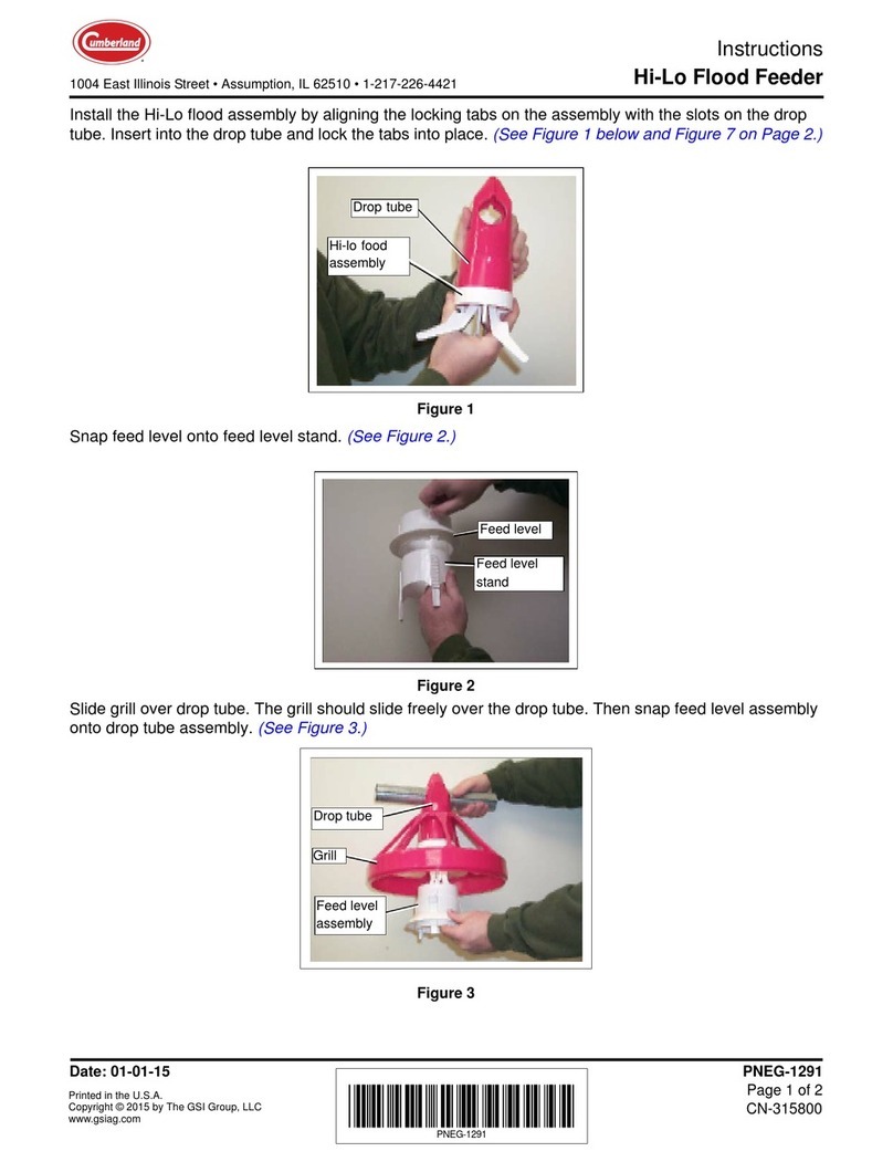
Hi-Lo Feeder Assembly
One-Piece Drop Tube
1. Place the grill on the drop tube (A) as shown in Figure 7A.
Figure 7A
2. Slide the proper number of feeder assemblies onto each auger tube. The tube rib (C) slides through
the slot (B) at the top of the drop tube. (See Figure 7B.)
Figure 7B
Do not connect the system to the electrical mains until the final stage of
installation. Failure to observe critical sequencing could prove fatal.
A
Ref # Description
ADrop Tube
B
C
Ref # Description
BSlot
C Rib

7. Installation
20 PNEG-250 Hi-Lo and PRO-1 Pan Feeders
Two-Piece Drop Tube
1. Place the top piece of the two-piece drop tube over the hole opening on the tube.
(See Figure 7C.)
Figure 7C
Figure 7D
2. Push the grill up on to the top piece of the two-piece drop tube. (See Figure 7D.)
3. Slide the bottom piece of the two-piece drop tube into the top piece, making certain the tabs (A) are
locked in place. (See Figure 7E.)
Figure 7E
Top
Bottom
A
Ref # Description
ATabs
Other manuals for Hi-Lo
2
This manual suits for next models
1
Table of contents
Other Cumberland Farm Equipment manuals

Cumberland
Cumberland 6500 Series Specification sheet

Cumberland
Cumberland FLX-5639 User manual

Cumberland
Cumberland Farm Hand Swine Finisher User manual

Cumberland
Cumberland Hi-Lo User manual

Cumberland
Cumberland PNEG-240 User manual

Cumberland
Cumberland Integra Feed-Link User manual

Cumberland
Cumberland Integra Feed-Link User manual

Cumberland
Cumberland U-Series User manual

Cumberland
Cumberland Hi-Lo Flood Feeder User manual