Grouser Products Ag Pro Plus HD User manual

Ag Pro Plus HD
Owner’s Manual & Parts Book
Date 3-25-2020
PN: 42414
Purchase Date
Serial Number
Model Number
Tractor Model
Dealer
Grouser Products
755 2nd Ave NW - West Fargo, ND 58078
Phone: 1-800-747-6182
Fax: 1-701-282-8131
E-mail: grouser@grouser.com
Website: www.grouser.com
Serial Number: 10206071-Current

2
Description Page
Welcome To The Owner & Torque Specications 2
Safety Precautions & Pre-Installation 3
Maintenance & Lubrication 3
Lift System 4-5
Tractor Side Hydraulics 5-7
Initial Startup 8
Hydraulic Angle System Operation & Relief Valve Adjustment 9
Connecting and Disconnecting 10
Skid Shoe Adjustment & Tilt Plate Adjustment 11
Ag Pro Plus HD Blade 12-13
Hydraulic Angle - Hydraulic Tilt System 14-15
Hydraulic Angle - Hydraulic Tilt Electric Hydraulics 16-17
Hydraulic Mulit-Coupler Maintenance 18-19
Notes 20
Hydraulic Schematics 21
Notes 22-23
Contact Us, Improvements, & Warranty 24
Thank you for your recent purchase of a Grouser Ag Pro Plus HD Dozer. Welcome to the family of satised Grouser blade owners.
Grouser Products is committed to offering quality products to help professionals in their daily jobs. We are also committed to
providing you the highest level of customer satisfaction possible. Again, thank you for your patronage. We look forward to serving
you.
This manual contains information concerning the operation, adjustment, safety and maintenance of the Ag Pro 660HD Dozer. You
have purchased a dependable, long lasting piece of equipment. You can expect to receive long lasting performance and long
service built into our products with proper care and operation. Please have all operators read and understand this manual carefully.
Keep the manual available for reference. If, for any reason, you have questions or comments, we would be happy to hear from you.
Call our toll-free number, 800-747-6182, or send us an e-mail at [email protected]. You can expect us to respond to your e-mail in
a timely manner.
Tighten all bolts to the values listed below unless otherwise noted. Refer to the parts lists for proper length and grade of the bolts.
Torque - Dry (ft–lbs)
SAE Grade 5 SAE Grade 8
Size UNC UNF UNC UNF
5/16 17 19 24 27
3/8 30 35 45 50
7/16 50 55 70 80
1/2 75 85 110 120
9/16 110 120 150 170
5/8 150 170 210 240
3/4 260 300 380 420
7/8 430 470 600 670
1 640 720 910 1020
Torque - Dry (ft-lbs)
Size Grade 10.9
M18 x 2.50 284
M20 x 2.50 401
M22 x 2.50 547
M24 x 3.00 694
ContentsWelcome to the OwnerTorque Specications

3
A careful operator is the best operator. Most accidents can be avoided by observing certain precautions. To help prevent
accidents, read and take the following precautions before operating this equipment. In addition, please follow all safety and
operational instructions of your tractor manufacturer.
The Ag Pro Plus HD Dozer:
1. The Ag Pro Plus HD Dozer should be operated only by those who are responsible and instructed to do so.
2. Read the owner’s manual carefully before using this equipment. Lack of operating knowledge can lead to accidents.
3. Keep the Ag Pro Plus HD Dozer maintained in reliable and satisfactory condition to ensure your safety.
4. Make sure the area is clear of people before moving any equipment.
5. Do not modify or permit anyone else to modify or alter the equipment and its components without rst consulting Grouser
Products.
6. Lower the blade to the ground when not in use.
Servicing the Ag Pro Plus HD Dozer:
1. Read and follow all safety instructions provided by the tractor manufacturer.
2. Always use proper personal safety gear when performing maintenance on equipment.
3. Before servicing, relieve hydraulic pressure, stop engine and fully engage parking brake.
4. Escaping hydraulic uid under pressure can penetrate skin causing serious injury. If uid is injected into skin, obtain medical
attention immediately.
– DO NOT use your hand to check for leaks. Use a piece of cardboard or paper to search for leaks.
– Stop the engine and relieve pressure before connecting or disconnecting lines.
– Tighten all connections before starting the engine or pressurizing lines.
Storing the Ag Pro Plus HD:
1. Thoroughly clean the Ag Pro Plus HD Dozer before storage. Use paint where necessary to prevent rust.
2. Check the Ag Pro Plus HD Dozer for worn or damaged parts. Install new parts as required.
3. Lubricate all pins and joints.
Safety Precautions Pre-Installation
Unstrap and remove the lift frame, hoses, top arms, and any boxes of hardware from the undercarriage. If any components are
missing, call Grouser.
Install undercarriage per the tractor specic mounting instructions.
Maintenance & Lubrication
Due to the harsh environment this equipment operates in, the following tasks should be performed
every 10 hours or less.
• Inspect all equipment before operation for existing or potential damage.
• Lubricate all joints with high quality grease. See below for grease locations.
• Inspect all bolts, and tighten any loose bolts to torque specications on page 2.
• Check replaceable cutting edge for wear ensuring there is enough material to prevent permanent damage to the Ag Pro 660HD
Dozer. For cutting edge information, see pages 13 .
• Check hydraulic cylinders and hoses for damage or leaks. For replacement parts, see hydraulic pages 4, 6-7 and 16-17.
• Make sure all non-rotating pins are secured properly.
• Inspect all decals and order replacement decals from your dealer if any are damaged or worn.
• For multi-coupler maintenance, see pages 18-19.
• Inspect all tilt-ways for wear. See page 11 for tilt plate adjustment.
• Replace parts with original parts only.

4
Lift System
42440
DWG. NO.:
22
26
14
13
1
3
17
is needed. The number is stamped on the base end of the cylinder
opposite of the hydraulic ports.
Note: When ordering a cylinder seal kits, the part number on the cylinder
28
8
5
29
16
6
27
27
28
11
12
2
10
19
21
7
20
9
28
15
9
27 18
31
4
28
24
30
25
23
ITEM
NO. QTY. PART NO. DESCRIPTION
1 1 11-40760-L Ag Pro Plus Manual Pitch Top Arm Assy
2 1 11-40760-R Ag Pro Plus Manual Pitch Top Arm Assy
3 2 16-20002 1/4" x 3/4 " Hex Bolt Gr 5 NC
4 2 16-20214 3/4" x 1" Hex Bolt Gr 5 NC
5 2 16-20216 3/4" x 1-1/2" Hex Bolt Gr 5 NC
6 4 16-20217 3/4" x 1-3/4" Hex Bolt Gr 5 NC
7 4 16-20220 3/4" x 2-1/2" Hex Bolt Gr 5 NC
8 10 16-20566 1" X 4" Hex Bolt Gr 8 NC
9 8 19-13515 Spacer, NR Pin
10 2 19-13525 2.75 x 2.50 x 4.75 Spring Bushing
11 8 19-16695 2.25 x 2.00 x 1.50 Spring Bushing
12 2 19-18089 2.75 x 2.50 x 3.75 Spring Bushing
13 2 26-34751 5 x 18 Hydraulic Cylinder
14 2 27-9503 Pinch Decal (Foot)
15 1 32-19120 HD Lift Frame
16 1 34-14961 Manual Canister Small
ITEM
NO. QTY. PART NO. DESCRIPTION
17 2 43-14725 Lift Frame / UC Pin
18 4 43-18120 Top Pin Weld
19 2 43-18127 Top Arm Pin Weld
20 2 43-18175 Lift Cyl Pin Weld
21 2 43-18635 Ag Pro Plus QA Pin
22 1 45-18110-L Male Quick Attach, Ag Pro S
23 1 45-18110-R Male Quick Attach, Ag Pro S
24 2 57-1530 3" OD X .75 ID X .25" HD Flat Washer
25 6 57-1811 2” Washer
26 2 57-20740 1/4" Flat Washer
27 10 57-20747 3/4" Flat Washer
28 12 58-9369 Straight 1/8" NPT Grease Zerk
29 10 70-20599 1" Hex Nut Gr 8 NC
30 2 70-20607 3/4" Center Lock Hex Nut Gr 2 NC
31 2 70-20610 1/4" Nyloc Hex Nut Gr 5 NC
No. On
Cylinder Part No. Description
26-34751 49-12275 Monarch Seal Kit 5" (658457) Nitrided Rod

5
Some assembly of Lift System components is necessary. Follow the steps listed below. See diagram below for the correct hardware
and orientation of parts.
1. Remove all pins and fasteners on each side of the undercarriage and set aside for later installation.
2. Position the lift frame between the two plates on both sides of the undercarriage and align to the bottom holes.
3. Insert pins and hardware to attach the lift frame, the base end of the lift cylinders, and the top arms to the undercarriage.
4. Insert pins and hardware to attach the male quick attaches to the lift frame, and to the top arms.
5. Torque all fasteners according to the specications on Page 2.
Lift System Tractor Side Hydraulics
Note: Refer to Pages 6-7 for the correct hose lengths and hose location.
Note: All connections are identied by spiral bands. 2 bands are from the base end of a cylinder and 1 band is from the
rod end of a cylinder. Orange = Lift, Green = Tilt, Red = Angle, and Yellow = Angle 2-Stick
1. Connect the lift hoses to the lift cylinders.
2. Verify that hoses are not twisted and protected from rubbing on any sharp edges. See Pages 6-7 for proper hose routing.
3. Attach the multi-coupler to the top arm mount and install the 45° ttings.
4. Identify each remaining hose at the front of the undercarriage by the colored bands on the end of the hose and connect the
hose to the corresponding 45° tting on the multi-coupler. Refer to Pages 6-7 for proper hose locations.
5. Hoses were plugged into the rear of the tractor during the undercarriage installation.
6. Continue on Page 8 for initial startup instructions.

6
Tractor Side Hydraulics
ITEM
NO. QTY. PART NO. DESCRIPTION
1 4 16-18957 5/16” x 3-1/4” Allen Head Screw
2 1 25-19861 Multi-Coupling Plate - 5 Port - Fixed
3 1 25-19863 Multi-Coupling Plate - 5 Port - Cap
4 5 25-19870 Multi-Coupling Plate - Male Coupler
5 2 25-3401 Pioneer Dust Cap Left Angle (Yellow)
6 8 25-34342 Tappet Quick Coupler Male - Poppet Style
7 2 25-3453 Pioneer Dust Cap Tilt (Green)
8 2 25-3455 Pioneer Dust Cap Angle (Red)
9 2 25-3457 Pioneer Dust Cap Lift (Orange)
10 5 25-40407 Multi-Coupling Plate - Snap Ring
11 2 31-11699-10-10 JIC Union
12 5 31-15199-8-8 JIC Union Elbow 90°
13 2 31-34032 Bulkhead Run Tee JIC
14 4 31-34042 Straight JIC x O-Ring
15A,B 6 31-34051 Straight Thread Elbow 90° JIC x O-Ring
15C 6 31-6802-08-10 Straight Thread Elbow 45° JIC x O-Ring
16A,B 2 31-34059 Straight Thread Elbow 90° JIC x O-Ring
16C 2 31-6802-12-10 Straight Thread Elbow 45° JIC x O-Ring
17 1 31-34090 Swivel Nut Run Tee JIC
18 1 31-34100 Swivel Nut Elbow 90° JIC
19 5 31-34150 Straight Thread Elbow 45° JIC x O-Ring
20 2 34-12932 Cylinder Saddle
21 2 34-12933 Hose Clamp (worm drive - 4.5)
22 9 34-18888-GR -12 Green - Spiral Band
*Parts Not Shown
Hoses Not Drawn to Scale
Item A for CNH, JD 9R, JD 9030
Item B for Versatile, Challenger MT900, and JD 9RX
Item C for Claas Xerion Tractor
Every hydraulic function from the front to the back of the system is
designated by a and a letter and can also be referenced on the Hydraulic
Schematics on Page 21.
Designated Hose
Locations
ITEM
NO. QTY. PART NO. DESCRIPTION
23 10 34-18888-RD -12 Red - Spiral Band
24 4 34-18888-YL -12 Yellow - Spiral Band
25 15 34-19494-OR -16 Orange - Spiral Band
26 1 35-12631-0350 35" x 1/2" -8JIC / -8JIC Abrasion Resistant Hose
27 3 35-12631-0780 78” x 1/2" -8JIC/-8JIC Abrasion Resistant Hose
28 2 35-12631-0810 81” x 1/2" -8JIC/-8JIC Abrasion Resistant Hose
29A,C 5 35-12631-2930 293" (24.42”) x 1/2" -8JIC/-8JIC Abrasion Resistant Hose
29B 5 35-12631-3200 320" (26.67”) x 1/2" -8JIC/-8JIC Abrasion Resistant Hose
30A,C 2 35-12637-2930 293" (24.42”) x 3/4" -12JIC/-12JIC Abrasion Resistant Hose
30B 2 35-12637-3200 320" (26.67”) x 3/4" -12JIC/-12JIC Abrasion Resistant Hose
31 1 35-12641-0515 51.5” x 5/8" -10JIC/-12JIC Abrasion Resistant Hose
32 1 35-12641-0535 53.5” x 5/8" -10JIC/-12JIC Abrasion Resistant Hose
33 1 35-12641-0665 66.5” x 5/8" -10JIC/-12JIC Abrasion Resistant Hose
34 1 35-12641-0670 67” x 5/8" -10JIC/-12JIC Abrasion Resistant Hose
35 2 35-18240 Lift Cylinder Steel Line
36 4 70-20611 5/16" Nyloc Hex Nut Gr. 5
37 2 70-20809 1-1/16" Hex Jam Nut
NOTE: All hoses are marked with colored spiral
bands and should be attached to designated
ports on the Multi-Coupler.
View of Left Side Hoses
1 Orange Spiral Band
From The Front
2 Orange Spiral Bands
Angle Hoses (Red Spiral Bands)
(Orange Spiral Bands)
Lift Base Hose (Orange Spiral Bands)
Lift Rod Hose Tilt Hoses (Green Spiral Bands)
T-Fitting on the Angle System.
Connected to Hose from the
C
DETAIL C
Angle Rod
Extend Right Angle on SCV
Retract Left Angle on SCV
Retract Right Angle on SCV
Angle Right Base A
Red Spiral Band (X2)
Extend Left Angle on SCV
Angle Left Base D
Yellow & Red Spiral Band
Yellow Spiral Band (X1)
B
35" Hose
27
28
Yellow Spiral Band (X1)
Right Angle Base A
Red Spiral Band (X2)
Green Spiral Band (X2)
F
Tilt Base
Green Spiral Band (X1)
E
Tilt Rod
Red Spiral Band (X1)
D
Left Angle Base
Angle Rod B
10
25 14
3320
31
34
12
7
8
24
1411
G
19
13
37
25
35 21
30 9
32
DETAIL A
See Detail B for correct
hose locations
33
23
D
A
F
E
H
G
H
G
H
22
25
23
DETAIL B
10
16
6
22
3
2
4
1
36
29
26
29
5
6
15
17
18
24
A
B
C
23
C

7
Tractor Side Hydraulics
ITEM
NO. QTY. PART NO. DESCRIPTION
1 4 16-18957 5/16” x 3-1/4” Allen Head Screw
2 1 25-19861 Multi-Coupling Plate - 5 Port - Fixed
3 1 25-19863 Multi-Coupling Plate - 5 Port - Cap
4 5 25-19870 Multi-Coupling Plate - Male Coupler
5 2 25-3401 Pioneer Dust Cap Left Angle (Yellow)
6 8 25-34342 Tappet Quick Coupler Male - Poppet Style
7 2 25-3453 Pioneer Dust Cap Tilt (Green)
8 2 25-3455 Pioneer Dust Cap Angle (Red)
9 2 25-3457 Pioneer Dust Cap Lift (Orange)
10 5 25-40407 Multi-Coupling Plate - Snap Ring
11 2 31-11699-10-10 JIC Union
12 5 31-15199-8-8 JIC Union Elbow 90°
13 2 31-34032 Bulkhead Run Tee JIC
14 4 31-34042 Straight JIC x O-Ring
15A,B 6 31-34051 Straight Thread Elbow 90° JIC x O-Ring
15C 6 31-6802-08-10 Straight Thread Elbow 45° JIC x O-Ring
16A,B 2 31-34059 Straight Thread Elbow 90° JIC x O-Ring
16C 2 31-6802-12-10 Straight Thread Elbow 45° JIC x O-Ring
17 1 31-34090 Swivel Nut Run Tee JIC
18 1 31-34100 Swivel Nut Elbow 90° JIC
19 5 31-34150 Straight Thread Elbow 45° JIC x O-Ring
20 2 34-12932 Cylinder Saddle
21 2 34-12933 Hose Clamp (worm drive - 4.5)
22 9 34-18888-GR -12 Green - Spiral Band
*Parts Not Shown
Hoses Not Drawn to Scale
Item A for CNH, JD 9R, JD 9030
Item B for Versatile, Challenger MT900, and JD 9RX
Item C for Claas Xerion Tractor
Every hydraulic function from the front to the back of the system is
designated by a and a letter and can also be referenced on the Hydraulic
Schematics on Page 21.
Designated Hose
Locations
ITEM
NO. QTY. PART NO. DESCRIPTION
23 10 34-18888-RD -12 Red - Spiral Band
24 4 34-18888-YL -12 Yellow - Spiral Band
25 15 34-19494-OR -16 Orange - Spiral Band
26 1 35-12631-0350 35" x 1/2" -8JIC / -8JIC Abrasion Resistant Hose
27 3 35-12631-0780 78” x 1/2" -8JIC/-8JIC Abrasion Resistant Hose
28 2 35-12631-0810 81” x 1/2" -8JIC/-8JIC Abrasion Resistant Hose
29A,C 5 35-12631-2930 293" (24.42”) x 1/2" -8JIC/-8JIC Abrasion Resistant Hose
29B 5 35-12631-3200 320" (26.67”) x 1/2" -8JIC/-8JIC Abrasion Resistant Hose
30A,C 2 35-12637-2930 293" (24.42”) x 3/4" -12JIC/-12JIC Abrasion Resistant Hose
30B 2 35-12637-3200 320" (26.67”) x 3/4" -12JIC/-12JIC Abrasion Resistant Hose
31 1 35-12641-0515 51.5” x 5/8" -10JIC/-12JIC Abrasion Resistant Hose
32 1 35-12641-0535 53.5” x 5/8" -10JIC/-12JIC Abrasion Resistant Hose
33 1 35-12641-0665 66.5” x 5/8" -10JIC/-12JIC Abrasion Resistant Hose
34 1 35-12641-0670 67” x 5/8" -10JIC/-12JIC Abrasion Resistant Hose
35 2 35-18240 Lift Cylinder Steel Line
36 4 70-20611 5/16" Nyloc Hex Nut Gr. 5
37 2 70-20809 1-1/16" Hex Jam Nut
NOTE: All hoses are marked with colored spiral
bands and should be attached to designated
ports on the Multi-Coupler.
View of Left Side Hoses
1 Orange Spiral Band
From The Front
2 Orange Spiral Bands
Angle Hoses (Red Spiral Bands)
(Orange Spiral Bands)
Lift Base Hose (Orange Spiral Bands)
Lift Rod Hose Tilt Hoses (Green Spiral Bands)
T-Fitting on the Angle System.
Connected to Hose from the
C
DETAIL C
Angle Rod
Extend Right Angle on SCV
Retract Left Angle on SCV
Retract Right Angle on SCV
Angle Right Base A
Red Spiral Band (X2)
Extend Left Angle on SCV
Angle Left Base D
Yellow & Red Spiral Band
Yellow Spiral Band (X1)
B
35" Hose
27
28
Yellow Spiral Band (X1)
Right Angle Base A
Red Spiral Band (X2)
Green Spiral Band (X2)
FTilt Base
Green Spiral Band (X1)
ETilt Rod
Red Spiral Band (X1)
DLeft Angle Base
Angle Rod B
10
25 14
3320
31
34
12
7
8
24
1411
G
19
13
37
25
35 21
30 9
32
DETAIL A
See Detail B for correct
hose locations
33
23
D
A
F
E
H
G
H
G
H
22
25
23
DETAIL B
10
16
6
22
3
2
4
1
36
29
26
29
5
6
15
17
18
24
A
B
C
23
C

8
Prior to operating the blade system, all air must be purged from the hydraulic system. Follow the steps below for each function on
your blade.
Lift Function:
1. With the lift frame down and blocked, loosen the ttings on both ends of the lift cylinders.
2. Actuate the raise function to supply oil to the rod end of the cylinders.
3. When oil starts to ow from the ttings, stop oil ow, and tighten the tting on the rod end of the lift cylinders.
4. Continue to ow oil until the system is fully raised and then block the lift frame.
5. Actuate the function in the opposite direction to supply oil to the base end of the lift cylinders.
6. When all air is removed from the lift system, stop oil ow and tighten the ttings on the base end of the lift cylinders.
7. Raise lift system and remove blocks. Cycle up and down 5 more times.
8. Check tractor oil level and ll if necessary.
9. Continue with connecting the blade on Page 10.
Tilt Function:
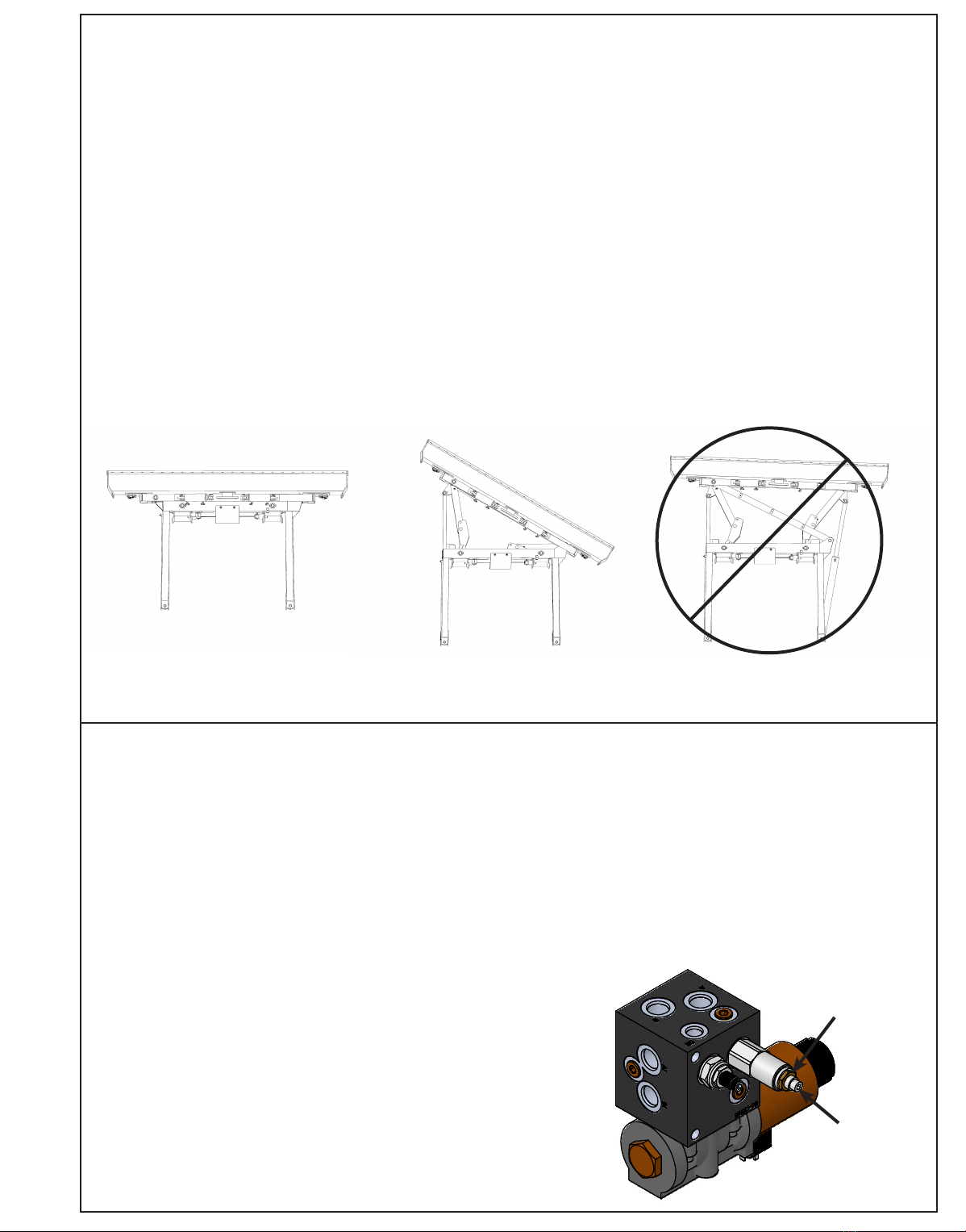
1. Use a lift or jack to tilt the blade system until the left side is fully up, loosen the ttings on the rod and base end of both tilt cylinders.
2. Actuate the tilt function to extend the right tilt cylinder and supply oil to the base end of the right cylinder and to the rod end of the
left cylinder.
3. When oil starts to ow from the ttings, stop oil ow, and tighten the tting on the base end of the right cylinder and rod end of
the left cylinder.
4. Remove the lift or jack.
5. Continue to actuate the tilt function until oil ows out of the remaining open ports.
6. Actuate the tilt function in the opposite direction.
7. When all air is removed from the tilt system, stop oil ow, and tighten the remaining ttings on the cylinders.
8. Cycle both cylinders in and out 5 more times.
9. Check tractor oil level and ll if necessary.
Angle Function:
1. Loosen the ttings on the rod and base end of the left angle cylinder.
2. Actuate the angle function to extend the left angle cylinder and supply oil to the base end of the left cylinder.
3. When oil starts to ow from the ttings, stop oil ow, and tighten the tting on the base end of the left cylinder.
4. Continue to actuate the left angle function in the same direction until the cylinder is fully extended.
5. Actuate the left angle function in the opposite direction.
6. When oil starts to ow from the rod end tting, stop oil ow, and tighten the rod end tting on the left angle cylinder.
7. Continue to actuate the left angle fuction until cylinder is fully retracted.
8. Loosen the ttings on the rod and base end of the right angle cylinder.
9. Actuate the angle function to extend the right angle cylinder and supply oil to the base end of the right cylinder.
10. When oil starts to ow from the ttings, stop oil ow, and tighten the tting on the base end of the right cylinder.
11. Continue to actuate the right angle function in the same direction until the cylinder is fully extended.
12. Actuate the right angle function in the opposite direction.
13. When oil starts to ow from the rod end tting, stop oil ow, and tighten the rod end tting on the right angle cylinder.
14. Continue to actuate the right angle function until cylinder is fully retracted.
15. Cycle the left cylinder in and out 5 more times and then the right cylinder in and out 5 more times.
16. Check tractor oil level and ll if necessary.
Run the blade through all the functions. If any function does not operate correctly, refer to corresponding section above and re-
bleed. If problem still persists, call Grouser Products.
Initial Startup

9
CORRECT CORRECT
(Left or Right)
When either angle cylinder reaches the end of its stroke and the safety relief valve reroutes pressure to the opposite cylinder
causing it to extend, adjust the relief valve. To set the electric safety relief valve at a higher pressure than tractor: Use a pressure
gauge connected between the tractor pump and the port A on the electric relief valve on the blade to check the tractor pressure and
record the reading. To increase the pressure of the relief valve, install a 0-5,000 psi pressure gauge between the hose and tting
in the base end of right angle cylinder. Make sure both angle cylinders are retracted. Loosen the jam nut on the valve system relief
cartridge. Next, start tractor and extend the right side cylinder out until the safety valve activates, while the safety valve is in function
(pressure being rerouted to opposite cylinder causing opposite cylinder to extend), record the pressure reading on the gauge.
Tighten the Allen screw in small increments and record the pressure until the pressure is about 50-100 psi higher than the tractor
pressure. Do not exceed the 3,500-psi operating pressure of the cylinders. Tighten the jam nut and remove the gauge.
CAUTION: Do not bypass the safety relief valve and plumb each cylinder to separate valves on the tractor.
Hydraulic Angle System Operation Relief Valve Adjustment
Incorrect
Jam Nut
Allen Screw
With the Electric Hydraulic Angle Option, you will have the ability to angle the blade 30 degrees left or right. To achieve these
angles, the two cylinders are designed to operate independently of each other through an electric diverter valve. To angle the blade
to the left, actuate the tractor hydraulic control lever in the cab with the diverter valve un-powered. To angle the blade to the right,
apply power to the diverter valve and then actuate the tractor hydraulic control lever.
The safety relief valve allows the cylinder to retract if its internal pressure becomes excessive. With this safety feature in place,
when either cylinder reaches the end of its stroke, the safety relief valve will reroute pressure to the opposite cylinder causing it to
extend. If this occurs, refer to the Relief Valve adjustment below for possible adjustments. Only one cylinder should be extended
when angled dozing.
With the 2-Stick Hydraulic Angle Option, you will have the ability to angle the blade 30 degrees left or right. To achieve these
angles, the two cylinders are designed to operate independently of each other with the use of 2 tractor hydraulic control levers and
a safety relief valve. To angle the blade to the left or right, actuate the tractor hydraulic control lever corresponding to the left or
right cylinder.
To ensure proper use and life of equipment, it is recommended to have both cylinders closed for straight ahead dozing and only
one cylinder partially or fully extended for angled dozing as shown in the diagrams below. If the angle system is not used correctly,
frame damage may occur. Diagrams below may look slightly different than your system, but the information is still compatible and
important to your system.

10
To Connect:
Note: If necessary, use a spotter to help center the blade on the lift system.
1. Before standing blade upright for initial connection, remove the 3/4” pin (#20 on Page 12) so the skid shoes can move freely.
The blade will lean back further for easier connection. Store the pin in the storage location (See Page 11 for location).
2. If necessary, lift the locking latch and pull the quick attach lock handle on the left side of the lift system to open the quick
attach system. Refer to Page #14-15 for further clarication on the quick attach system.
3. Drive the tractor forward slowly until the top edge of the male quick attach is under the top hook of the female quick attach on
the blade assembly.
4. Raise the lift system until the male quick attach engages the female hook. If both sides don’t fully engage, reposition.
Continue to raise the lift system until the blade is off the ground and the female quick attaches are against the front of the male
quick attaches.
5. Shut off the tractor engine and set the parking brake.
6. Push the quick attach lock handle to engage the quick attach pins and lift the locking latch to lock the handle in place.
7. Clean and connect hydraulic multi-coupler on the top arm. Refer to Pages 18-19 for cleaning and connecting information.
8. If applicable, plug the male blade break away end of the wire harness into the female blade break away end of the wire
harness on the top arm.
9. Lock the mushroom skid shoe link back in place with the 3/4” pin you removed in Step #1.
10. If initial startup, refer to Page 8 before operating any function of the blade.
To Disconnect:
1. Lower the blade until the cutting edge is off the ground a few inches.
2. Shut off the tractor engine and set the parking brake.
3. Unhook the multi-coupler on the top arm.
4. Remove the multi-coupler cover from the parking station on the blade assembly and install on the multi-coupler on the top arm.
5. Plug the blade side multi-coupler into the parking station.
6. Lift the locking latch and pull the quick attach lock handle to disengage the quick attach pins.
7. Remove the 3/4” pin so the skid shoes can move freely and the blade can lean back. Store the pin.
8. Start tractor, disengage the parking brake, and lower the blade until cutting edge is on the ground.
9. Continue to slowly lower the lift system to disengage the blade.
10. Slowly back away from the blade. When lift system is clear from the blade, raise the lift system.
11. Shut off the tractor engine and set the parking brake.
Blade Connection and Disconnection

11
Figure 1
Skid Shoe Adjustment
Preferred Method:
1. The preferred blade position for adjusting the tilt plates is laying face down on blocks.
2. Remove the 6 bolts from the right tilt plates.
3. Add or remove washers as needed to adjust tilt-way clearance to 1/16” - 1/8”.
4. Reinstall the bolts in the right tilt plates.
5. Follow Steps #2-4 for the left tilt plates.
6. Once the tilt-way clearance is set, torque bolts to 640 ft-lbs.
Non-Preferred Method:
Note: Do not remove all of the bolts at the same time if the blade is not laying face down.
1. The non-preferred blade position for adjusting the tilt plates is
the blade in the upright position.
2. Remove the 3 bolts from the top right tilt plate and the
bottom left tilt plate..
3. Add or remove washers as needed to adjust tilt-way
clearance to 1/16” - 1/8”.
4. Reinstall the bolts in the top right tilt plate and the
bottom left tilt plate.
5. Follow Steps #2-4 for the bottom right tilt plate and
the top left tilt plate.
6. Once the tilt-way clearance is set, torque bolts to
640 ft-lbs.
Tilt Plate Adjustment
Figure 2
Forward/Reverse Lever
Handle
Receiver
Skid Shoe Adjustment:
1. Remove the handle from the ratchet keeper by pulling the
hitch clip pin and insert it into the handle receiver on the
ratchet jack.
2. Loosen the locking nut on the ratchet jack.
3. Hold the body of the ratchet jack and rotate the ratchet jack
handle to raise or lower the skid shoes.
4. If the skid shoe is not moving in the proper direction, ip
the forward/reverse lever on the handle (see Figure 2).
Rotate the ratchet jack handle again to move the skid
shoe in the desired direction.
5. After the skid shoe is adjusted, rotate the ratchet jack
handle until it rests against the ratchet keeper. Return the
removable handle to the ratchet keeper ensuring that the
ratchet jack handle is captured by the removable handle
and the ratchet keeper. Secure the handle to the ratchet
keeper with the hitch clip pin.
6. Tighten the locking nut against the ratchet jack body to
keep it from moving.
7. When skid shoes are worn up to the bolt heads, replace
skid shoes.
Removable
Handle
Handle
Receiver
Skid Shoe
Storage
Location
Locking
Location
Tilt Plate
Washers

12
Ag Pro HD Blade
ITEM NO. PART NO. 14'/QTY. 16'/QTY. 18'/QTY. DESCRIPTION
1 15-19110-14 1 - - HD Blade Weld
2 15-19110-16 - 1 - HD Blade Weld
3 15-19110-18 - - 1 HD Blade Weld
4 15-18520-14 1 - - Top Extension Weld
5 15-18520-16 - 1 - Top Extension Weld
6 15-18520-18 - - 1 Top Extension Weld
7 16-18945 2 2 2 1" x 3" Hex Bolt Gr 5 NC - Short Thread
8 16-20538 14 18 18 7/8" x 2" Hex Bolt Gr 8 NC
9 16-20562 12 12 12 1" x 3" Hex Bolt Gr.8 NC
10 16-20568 3 3 3 1" x 5" Hex Bolt Gr.8 NC
11 16-21064 8 8 8 3/8" x 1" Carriage Bolt Gr 5 NC
12 16-21666 4 4 4 5/8" x 1-3/4" Plow Bolt Gr 5 NC
13 16-21752 36 40 44 3/4" X 2" Plow Bolt Gr 8 NC
14 18-18498-L 1 1 1 Ratchet Keeper - Left
15 18-18498-R 1 1 - Ratchet Keeper - Right
16 27-14842-14 1 - - 14' Decal
17 27-14842-16 - 1 - 16' Decal
18 27-14842-18 - - 1 18' Decal
19 27-14845 1 1 1 Ag Pro Blade Decal
20 NA 1 1 1 Grouser Dozer Metal Serial Tag
21 27-40917 1 1 1 Ratchet Holder Storage Decal
ITEM NO. PART NO. 14'/QTY. 16'/QTY. 18'/QTY. DESCRIPTION
22 27-40951 1 1 1 Classic Decal
23 27-40962 1 1 1 Warning Prop 65 Decal
24 29-11118-6 2 - - 6' - 3/4”x 8” Cutting Edge
25 29-11118-7 - 2 - 7' - 3/4”x 8” Cutting Edge
26 29-11118-8 - - 2 8' - 3/4”x 8” Cutting Edge
27 29-19116-R,L 1 1 1 8" End Bit
28 29-19116-R,L 1 1 1 8" End Bit
29 34-17565 2 2 2 Skid Shoe Ratchet Jack
30 34-17567 2 2 2 Handle, Ratchet Jack
31 43-15712 2 2 2 3/4" x 3-1/4" Pin with Hitch Pin Clip
32 43-18463 4 4 4 1” x 2.75” Pin
33 43-18943 4 4 4 3/16” x 1-1/2” Cotter Pin
34 43-7767 2 2 2 Cylinder Pin Clip
35 44-14830 1 1 1 Custom Name Plate
36 44-15150 1 1 1 Ag Pro Dozer Name Plate
37 50-15458 2 2 2 12” Round Mushroom Skid Shoe
38 50-18470 2 2 2 Mushroom Skid Shoe Mount
39 52-12380R1 1 1 1 Center Tilt Way Cover
40 52-18299 4 4 4 Tilt Plate
41 57-20749 12 12 12 1" Flat Washer
42 57-20818 28 36 36 7/8" Flat Washer Heavy Duty Gr 8 (USS)
43 70-20598 14 18 18 7/8" Hex Nut Gr 8 NC
44 70-20622 8 8 8 3/8" Flange Hex Nut Gr 5 NC
45 70-20646 4 4 4 5/8" Hex Top Lock Nut Gr 5 NC
46 70-20647 36 40 44 3/4" Hex Top Lock Nut Gr 5 NC
47 70-20999 2 2 2 1" Hex Top Lock Nut Gr 8 NC (YZ)
48 75-18479 2 2 2 Skid Shoe Link
7
32
32
44
14
47
33
33
37
38
42
43
1,2,3
42
45
29
48
30
11
31
DETAIL A
SCALE 1 : 13
12
34
A
22
8
20
15
21
13
24,25,26
46
36
39
10
41
9
23
Item #36 for Ag Pro Dozer Name Plate and Item #35 for Custom Name Plate
27
19
16
40
4,5,6

13
Ag Pro HD Blade
ITEM NO. PART NO. 14'/QTY. 16'/QTY. 18'/QTY. DESCRIPTION
1 15-19110-14 1 - - HD Blade Weld
2 15-19110-16 - 1 - HD Blade Weld
3 15-19110-18 - - 1 HD Blade Weld
4 15-18520-14 1 - - Top Extension Weld
5 15-18520-16 - 1 - Top Extension Weld
6 15-18520-18 - - 1 Top Extension Weld
7 16-18945 2 2 2 1" x 3" Hex Bolt Gr 5 NC - Short Thread
8 16-20538 14 18 18 7/8" x 2" Hex Bolt Gr 8 NC
9 16-20562 12 12 12 1" x 3" Hex Bolt Gr.8 NC
10 16-20568 3 3 3 1" x 5" Hex Bolt Gr.8 NC
11 16-21064 8 8 8 3/8" x 1" Carriage Bolt Gr 5 NC
12 16-21666 4 4 4 5/8" x 1-3/4" Plow Bolt Gr 5 NC
13 16-21752 36 40 44 3/4" X 2" Plow Bolt Gr 8 NC
14 18-18498-L 1 1 1 Ratchet Keeper - Left
15 18-18498-R 1 1 - Ratchet Keeper - Right
16 27-14842-14 1 - - 14' Decal
17 27-14842-16 - 1 - 16' Decal
18 27-14842-18 - - 1 18' Decal
19 27-14845 1 1 1 Ag Pro Blade Decal
20 NA 1 1 1 Grouser Dozer Metal Serial Tag
21 27-40917 1 1 1 Ratchet Holder Storage Decal
ITEM NO. PART NO. 14'/QTY. 16'/QTY. 18'/QTY. DESCRIPTION
22 27-40951 1 1 1 Classic Decal
23 27-40962 1 1 1 Warning Prop 65 Decal
24 29-11118-6 2 - - 6' - 3/4”x 8” Cutting Edge
25 29-11118-7 - 2 - 7' - 3/4”x 8” Cutting Edge
26 29-11118-8 - - 2 8' - 3/4”x 8” Cutting Edge
27 29-19116-R,L 1 1 1 8" End Bit
28 29-19116-R,L 1 1 1 8" End Bit
29 34-17565 2 2 2 Skid Shoe Ratchet Jack
30 34-17567 2 2 2 Handle, Ratchet Jack
31 43-15712 2 2 2 3/4" x 3-1/4" Pin with Hitch Pin Clip
32 43-18463 4 4 4 1” x 2.75” Pin
33 43-18943 4 4 4 3/16” x 1-1/2” Cotter Pin
34 43-7767 2 2 2 Cylinder Pin Clip
35 44-14830 1 1 1 Custom Name Plate
36 44-15150 1 1 1 Ag Pro Dozer Name Plate
37 50-15458 2 2 2 12” Round Mushroom Skid Shoe
38 50-18470 2 2 2 Mushroom Skid Shoe Mount
39 52-12380R1 1 1 1 Center Tilt Way Cover
40 52-18299 4 4 4 Tilt Plate
41 57-20749 12 12 12 1" Flat Washer
42 57-20818 28 36 36 7/8" Flat Washer Heavy Duty Gr 8 (USS)
43 70-20598 14 18 18 7/8" Hex Nut Gr 8 NC
44 70-20622 8 8 8 3/8" Flange Hex Nut Gr 5 NC
45 70-20646 4 4 4 5/8" Hex Top Lock Nut Gr 5 NC
46 70-20647 36 40 44 3/4" Hex Top Lock Nut Gr 5 NC
47 70-20999 2 2 2 1" Hex Top Lock Nut Gr 8 NC (YZ)
48 75-18479 2 2 2 Skid Shoe Link
7
32
32
44
14
47
33
33
37
38
42
43
1,2,3
42
45
29
48
30
11
31
DETAIL A
SCALE 1 : 13
12
34
A
22
8
20
15
21
13
24,25,26
46
36
39
10
41
9
23
Item #36 for Ag Pro Dozer Name Plate and Item #35 for Custom Name Plate
27
19
16
40
4,5,6

14
Hydraulic Angle-Hydraulic Tilt System
42429
DWG. NO.:
ITEM NO. QTY. PART NO. DESCRIPTION
1 1 11-12397 Stabilizer Arm
2 1 11-19685 Angle Arm Assembly-R
3 1 11-19690 Angle Arm Assembly-L
4 1 11-40866 Bell Crank
5 1 16-20011 1/4" x 2-3/4" Hex Bolt Gr 5 NC
6 2 16-20130 1/2" x 2-1/2" Hex Bolt Gr 5 NC
7 4 16-20132 1/2" x 3" Hex Bolt Gr 8 NC
8 2 16-20424 1/2" x 3-1/2" Hex Bolt Gr 8 NC
9 3 16-20427 1/2" x 4-1/2" Hex Bolt Gr 8 NC
10 8 16-20560 1" x 2-1/2" Hex Bolt Gr 8 NC
11 2 16-21065 3/8" x 1-1/4" Carriage Bolt Gr 5 NC
12 4 16-21126 1/2" x 1-1/2" Carriage Bolt Gr 5 NC
13 2 19-40440 .378” ID x .503” OD x .375” Spacer
14 2 27-2409 Pinch Decal (Hand)
15 2 27-9503 Pinch Decal (Foot)
16 2 27-9504 Grouser Horizontal Decal
ITEM NO. QTY. PART NO. DESCRIPTION
17 1 32-18265 HA Tilt Frame
18 1 32-19675 Angle Frame
19 1 34-17799 Latch Spring
20 1 39-14663 Latch
21 1 39-14665 Handle Weld
22 1 39-3072 Rubber Handle
23 2 43-18486 AG Pro SS QA Lock Pin
24 1 43-8130 1-15/16" X 23-1/4" NR Pin
25 2 43-8131 1-15/16" X 31" NR Pin
26 1 43-8132 1-15/16" X 35-1/2" NR Pin
27 1 43-8133 1-15/16" X 7-1/8" NR Pin
28 2 43-8134 1-1/2" x 8" NR Pin
29 2 43-9352 1-1/2" X 7-1/2" NR Pin
30 1 44-40879 Plate, Link
31 4 44-8490 Spacer
32 1 45-40870-L SS Bolt in Quick Attach - Left
33 1 45-40870-R SS Bolt in Quick Attach - Right
34 2 57-20742 3/8" Flat Washer
35 4 57-20744 1/2" Washer
36 16 57-20819 1" Flat Washer Heavy Duty Gr 8
37 4 57-40408 3/8" Flat Nylon Washer
38 2 58-9371 45° 1/8" NPT Grease Fitting
39 6 58-9372 90° 1/8" NPT Grease Fitting
40 15 70-20604 1/2" Hex Center Lock Nut Gr. 2
41 2 70-20607 3/4" Center Lock Hex Nut Gr 2 NC
42 1 70-20610 1/4" Nyloc Hex Nut Gr 5 NC
43 2 70-20612 3/8" Nyloc Hex Nut Gr 5 NC
44 8 70-20999 1" Hex Top Lock Nut Gr 8 NC
45 2 75-40869 Link, Bell Crank To Pin
25
40
35
17
18
3
9
39
1
36
45 28
40
40
29
7
7
26
9
40
27
30
16
40
14
24
4
12
32
31
34
8
41
35
2
12
40
21
6
40
37
33
42
40
38
21
22
37
20
5
15
36
13
44
31
10
19
11
43
23
41

15
Hydraulic Angle-Hydraulic Tilt System
42429
DWG. NO.:
ITEM NO. QTY. PART NO. DESCRIPTION
1 1 11-12397 Stabilizer Arm
2 1 11-19685 Angle Arm Assembly-R
3 1 11-19690 Angle Arm Assembly-L
4 1 11-40866 Bell Crank
5 1 16-20011 1/4" x 2-3/4" Hex Bolt Gr 5 NC
6 2 16-20130 1/2" x 2-1/2" Hex Bolt Gr 5 NC
7 4 16-20132 1/2" x 3" Hex Bolt Gr 8 NC
8 2 16-20424 1/2" x 3-1/2" Hex Bolt Gr 8 NC
9 3 16-20427 1/2" x 4-1/2" Hex Bolt Gr 8 NC
10 8 16-20560 1" x 2-1/2" Hex Bolt Gr 8 NC
11 2 16-21065 3/8" x 1-1/4" Carriage Bolt Gr 5 NC
12 4 16-21126 1/2" x 1-1/2" Carriage Bolt Gr 5 NC
13 2 19-40440 .378” ID x .503” OD x .375” Spacer
14 2 27-2409 Pinch Decal (Hand)
15 2 27-9503 Pinch Decal (Foot)
16 2 27-9504 Grouser Horizontal Decal
ITEM NO. QTY. PART NO. DESCRIPTION
17 1 32-18265 HA Tilt Frame
18 1 32-19675 Angle Frame
19 1 34-17799 Latch Spring
20 1 39-14663 Latch
21 1 39-14665 Handle Weld
22 1 39-3072 Rubber Handle
23 2 43-18486 AG Pro SS QA Lock Pin
24 1 43-8130 1-15/16" X 23-1/4" NR Pin
25 2 43-8131 1-15/16" X 31" NR Pin
26 1 43-8132 1-15/16" X 35-1/2" NR Pin
27 1 43-8133 1-15/16" X 7-1/8" NR Pin
28 2 43-8134 1-1/2" x 8" NR Pin
29 2 43-9352 1-1/2" X 7-1/2" NR Pin
30 1 44-40879 Plate, Link
31 4 44-8490 Spacer
32 1 45-40870-L SS Bolt in Quick Attach - Left
33 1 45-40870-R SS Bolt in Quick Attach - Right
34 2 57-20742 3/8" Flat Washer
35 4 57-20744 1/2" Washer
36 16 57-20819 1" Flat Washer Heavy Duty Gr 8
37 4 57-40408 3/8" Flat Nylon Washer
38 2 58-9371 45° 1/8" NPT Grease Fitting
39 6 58-9372 90° 1/8" NPT Grease Fitting
40 15 70-20604 1/2" Hex Center Lock Nut Gr. 2
41 2 70-20607 3/4" Center Lock Hex Nut Gr 2 NC
42 1 70-20610 1/4" Nyloc Hex Nut Gr 5 NC
43 2 70-20612 3/8" Nyloc Hex Nut Gr 5 NC
44 8 70-20999 1" Hex Top Lock Nut Gr 8 NC
45 2 75-40869 Link, Bell Crank To Pin
25
40
35
17
18
3
9
39
1
36
45 28
40
40
29
7
7
26
9
40
27
30
16
40
14
24
4
12
32
31
34
8
41
35
2
12
40
21
6
40
37
33
42
40
38
21
22
37
20
5
15
36
13
44
31
10
19
11
43
23
41

16
Hydraulic Angle-Hydraulic Tilt - Electric Hydraulics
2
11
8
10
3
12
DETAIL A
10
F
13
E
D
14
A
B
10
DETAIL B
51
37
SCALE 1 : 7
DETAIL D
47
29
27
6
4
47
43
1
30
25
36 D
34
40
View is from Multi-Coupler Installed on Top Arm.Note:
All hoses are marked with colored spiral bands and should
be attached to designated ports on the Multi-Coupler.
4
46
29
50
38
32
37
28
DETAIL C
44
12
3
44
25
24
15
37
10
47
See Detail C for correct
hose locations
1
34
45
19
31
and a letter and can also be referenced on the
Hydraulic Schematic on Page 21.
24
24
E
26
35
B
3
F
9
A
49
21
18
16
22
A
48
41
5
7
39
designated by a
24
Note: Every hydraulic function from the front to the back of the system is
D
17
B
Note: The cylinder part number is stamped on the base end of the
cylinder opposite of the hydraulic ports.
No. On
Cylinder Part No. Description
26-34728 49-12272 Seal Kit 4” (647204) Nitrided Rod
26-34725 49-12274 Seal Kit 4” (647210) Nitrided Rod - Tube Ends
ITEM NO. QTY. PART NO. DESCRIPTION
1 4 16-20034 5/16" x 1" Hex Bolt Gr 5 NC
2 4 16-20035 5/16" x 1-1/4" Hex Bolt Gr. 5
3 4 16-20037 5/16" x 2" Hex Bolt Gr 5 NC
4 4 16-20040 5/16" x 2-1/2" Hex Bolt Gr 5 NC
5 4 16-20220 3/4" x 2-1/2" Hex Bolt Gr 5 NC
6 1 18-14695 Valve Bracket
7 1 18-1701 Valve Cover
8 4 18-19311-02-P-062 Half Hose Clamp
9 1 18-19311-02-P-062 Hose Clamp
10 7 18-19311-03-P-087 Hose Clamp
11 5 18-19312-02 Twin Cover Plate
12 5 18-19312-03 Twin Cover Plate
13 2 18-19313-03 Twin Stacking Bolt
14 2 18-19314-02 Twin Safety Plate
15 4 19-13515 Spacer, NR Pin
16 1 25-18961 Multi-Coupling Plate - 5/6 Port Parking Station
17 1 25-19862 Multi-Coupling Plate - 5 Port - Mobile
18 4 25-19865 Multi-Coupling - Female Coupler
19 4 25-40407 Multi-Coupling - Snap Ring
20 1 25-40413 Multi-Coupling Plate - Cap - Male
21 2 26-34725 4 x 43.5 Cylinder Tube Ends, Top Port
22 2 26-34728 4 x 12 Cylinder Tube Ends
23 1 31-34020 Bulkhead Branch Tee JIC
ITEM NO. QTY. PART NO. DESCRIPTION
24 9 31-34040 Straight JIC x O-Ring
25 3 31-34050 Straight Thread Elbow 90° JIC x O-Ring
26 1 31-34060 Branch Tee JIC x O-Ring
27 2 31-34070 Run Tee JIC x O-Ring
28 1 31-34080 Swivel Nut Branch Tee JIC
29 2 31-34100 Swivel Nut Elbow 90° JIC
30 2 31-34123 Hex Socket O-Ring Plug
31 6 34-18888-GR -12 Green - Spiral Band
32 6 34-18888-RD -12 Red - Spiral Band
33 2 34-18888-YL -12 Yellow - Spiral Band
34 2 35-12631-0450 45" x 1/2" -8 FJIC x -8 FJIC Abrasion Resistant Hose
35 2 35-12631-0690 69" x 1/2" -8 FJIC x -8 FJIC Abrasion Resistant Hose
36 1 35-12631-0720 72" x 1/2" -8 FJIC x -8 FJIC Abrasion Resistant Hose
37 2 35-12631-0770 77" x 1/2" -8 FJIC x -8 FJIC Abrasion Resistant Hose
38 2 35-12631-0960 96" x 1/2" -8 FJIC x -8 FJIC Abrasion Resistant Hose
39 1 35-12634-2120 212" x 3/8" -8 FJIC x -8 FJIC Abrasion Resistant Hose
40 1 35-12634-2220 222" x 3/8" -8 FJIC x -8 FJIC Abrasion Resistant Hose
41 4 43-16116R1 Pin Weld
42 1 56-13305 Hydraulic Valve
43 1 56-7772 Valve
44 4 57-20740 1/4" Flat Washer
45 2 57-20744 1/2" Washer
46 4 57-20747 3/4" Flat Washer
47 6 70-20581 5/16" Hex Nut Gr 5 NC
48 2 70-20604 1/2" Hex Center Lock Nut Gr. 2
49 4 70-20607 3/4" Center Lock Hex Nut Gr 2 NC
50 2 70-20611 5/16" Nyloc Hex Nut Gr. 5
51 1 70-20807 3/4" Hex Jam Nut NF
Green Spiral Band (X2)
20
Tilt Rod
D
Red Spiral Band (X1)
Yellow Spiral Band (X1)
A
Tilt Base
Right Angle Base
BAngle Rod
E
Green Spiral Band (X1)
Red Spiral Band (X2)
F
Left Angle Base
19

17
Hydraulic Angle-Hydraulic Tilt - Electric Hydraulics
2
11
8
10
3
12
DETAIL A
10
F
13
E
D
14
A
B
10
DETAIL B
51
37
SCALE 1 : 7
DETAIL D
47
29
27
6
4
47
43
1
30
25
36 D
34
40
View is from Multi-Coupler Installed on Top Arm.Note:
All hoses are marked with colored spiral bands and should
be attached to designated ports on the Multi-Coupler.
4
46
29
50
38
32
37
28
DETAIL C
44
12
3
44
25
24
15
37
10
47
See Detail C for correct
hose locations
1
34
45
19
31
and a letter and can also be referenced on the
Hydraulic Schematic on Page 21.
24
24
E
26
35
B
3
F
9
A
49
21
18
16
22
A
48
41
5
7
39
designated by a
24
Note: Every hydraulic function from the front to the back of the system is
D
17
B
Note: The cylinder part number is stamped on the base end of the
cylinder opposite of the hydraulic ports.
No. On
Cylinder Part No. Description
26-34728 49-12272 Seal Kit 4” (647204) Nitrided Rod
26-34725 49-12274 Seal Kit 4” (647210) Nitrided Rod - Tube Ends
ITEM NO. QTY. PART NO. DESCRIPTION
1 4 16-20034 5/16" x 1" Hex Bolt Gr 5 NC
2 4 16-20035 5/16" x 1-1/4" Hex Bolt Gr. 5
3 4 16-20037 5/16" x 2" Hex Bolt Gr 5 NC
4 4 16-20040 5/16" x 2-1/2" Hex Bolt Gr 5 NC
5 4 16-20220 3/4" x 2-1/2" Hex Bolt Gr 5 NC
6 1 18-14695 Valve Bracket
7 1 18-1701 Valve Cover
8 4 18-19311-02-P-062 Half Hose Clamp
9 1 18-19311-02-P-062 Hose Clamp
10 7 18-19311-03-P-087 Hose Clamp
11 5 18-19312-02 Twin Cover Plate
12 5 18-19312-03 Twin Cover Plate
13 2 18-19313-03 Twin Stacking Bolt
14 2 18-19314-02 Twin Safety Plate
15 4 19-13515 Spacer, NR Pin
16 1 25-18961 Multi-Coupling Plate - 5/6 Port Parking Station
17 1 25-19862 Multi-Coupling Plate - 5 Port - Mobile
18 4 25-19865 Multi-Coupling - Female Coupler
19 4 25-40407 Multi-Coupling - Snap Ring
20 1 25-40413 Multi-Coupling Plate - Cap - Male
21 2 26-34725 4 x 43.5 Cylinder Tube Ends, Top Port
22 2 26-34728 4 x 12 Cylinder Tube Ends
23 1 31-34020 Bulkhead Branch Tee JIC
ITEM NO. QTY. PART NO. DESCRIPTION
24 9 31-34040 Straight JIC x O-Ring
25 3 31-34050 Straight Thread Elbow 90° JIC x O-Ring
26 1 31-34060 Branch Tee JIC x O-Ring
27 2 31-34070 Run Tee JIC x O-Ring
28 1 31-34080 Swivel Nut Branch Tee JIC
29 2 31-34100 Swivel Nut Elbow 90° JIC
30 2 31-34123 Hex Socket O-Ring Plug
31 6 34-18888-GR -12 Green - Spiral Band
32 6 34-18888-RD -12 Red - Spiral Band
33 2 34-18888-YL -12 Yellow - Spiral Band
34 2 35-12631-0450 45" x 1/2" -8 FJIC x -8 FJIC Abrasion Resistant Hose
35 2 35-12631-0690 69" x 1/2" -8 FJIC x -8 FJIC Abrasion Resistant Hose
36 1 35-12631-0720 72" x 1/2" -8 FJIC x -8 FJIC Abrasion Resistant Hose
37 2 35-12631-0770 77" x 1/2" -8 FJIC x -8 FJIC Abrasion Resistant Hose
38 2 35-12631-0960 96" x 1/2" -8 FJIC x -8 FJIC Abrasion Resistant Hose
39 1 35-12634-2120 212" x 3/8" -8 FJIC x -8 FJIC Abrasion Resistant Hose
40 1 35-12634-2220 222" x 3/8" -8 FJIC x -8 FJIC Abrasion Resistant Hose
41 4 43-16116R1 Pin Weld
42 1 56-13305 Hydraulic Valve
43 1 56-7772 Valve
44 4 57-20740 1/4" Flat Washer
45 2 57-20744 1/2" Washer
46 4 57-20747 3/4" Flat Washer
47 6 70-20581 5/16" Hex Nut Gr 5 NC
48 2 70-20604 1/2" Hex Center Lock Nut Gr. 2
49 4 70-20607 3/4" Center Lock Hex Nut Gr 2 NC
50 2 70-20611 5/16" Nyloc Hex Nut Gr. 5
51 1 70-20807 3/4" Hex Jam Nut NF
Green Spiral Band (X2)
20
Tilt Rod
D
Red Spiral Band (X1)
Yellow Spiral Band (X1)
A
Tilt Base
Right Angle Base
BAngle Rod
E
Green Spiral Band (X1)
Red Spiral Band (X2)
F
Left Angle Base
19

18
Hydraulic Multi-Coupler Maintenance
A
B
D
C
DD
C
D
D
D D
B
D
A
C
D
B
D
Mobile HalfFixed Half
On the pins.
station.
A.
Apply a lubricant/anti-corrosion (grease or silicone - see Note 1):
Inside the cam.B.
In the locking mechanism area.C.
Connect the cap to the fixed half and the mobile half to the parking4.
3.
Before Each Use:
Disconnect the mobile half from the parking station and the cap from1.
the fixed half.
Check that there is no contamination (salt, sand, dirt, etc.):2.
On the pins.A.
Inside the cam.B.
In the locking mechanism area.C.
On the face of the plates and couplings.D.
In case of contamination, remove it with a cloth and/or compressed air.3.
Check that there is still a lubricant/anti-corrosion (grease or silicone -4.
see Note 1):
On the pins.A.
Inside the cam.B.
In the locking mechanism area.C.
Connect the mobile and fixed halves together.5.
After Each Use:
Disconnect the mobile half from the fixed half.1.
Clean all contamination (salt, sand, dirt, etc.) from the following areas:2.
On the pins.A.
Inside the cam.B.
In the locking mechanism area.C.
On the face of the plates and couplings.D.
*Use a cloth or compressed air. It is advised to not use water to clean
these surfaces
Note 1:
When sand and salt are present, or the plates under go a washdown,
a heavy duty silicone spray lubricant should be used to replace
grease from the factory. The lubricant should help protect from
corrosion without collecting dust and contaminants, and will resist
washing off when exposed to water.
Recommended Lubricant Brands:
Fluid Film (Aerosol or Non-Aerosol), LPS-2 Heavy Duty Lubricant, or
CRC 3-36.
D
A
D

19
Hydraulic Multi-Coupler Maintenance
Cleaning The Male Interface Seal:
1. Make sure the coupling is securely fastened
into the plate or place in a vice.
2. Using a blunt, non-marring tool, depress the
valve face until the seal is exposed. Insert a
bent metal wire between the valve face and
the body of the coupling. Use caution not to
damage or scratch the seal when inserting
the wire.
3. Inspect the seal and interior surfaces for
contamination.
4. In case of contamination, carefully
wipe surfaces with a soft cloth, or use
compressed air to blow the contamination
out. Do Not press hard on the seal as
contamination can scratch the seal surface.
5. Using a non-marring tool, depress the valve
face and remove the metal wire. Release
the valve to the ush position.
Cleaning The Female Bushing:
1. Make sure the coupling is securely fastened
into the plate or place in a vice.
2. Using a non-marring tool, depress the
outer ring to expose the bushing. There is
no need to expose the valve seal, so stop
pressing before the valve is opened.
3. Inspect the interior body and bushing
surfaces for contamination.
4. In case of contamination, carefully
wipe surfaces with a soft cloth, or use
compressed air to blow the contamination
out.
5. Release the outer ring so that it returns to
the ush position.

20
Notes
Page Left Blank Intentionally
Other manuals for Ag Pro Plus HD
1
Table of contents
Other Grouser Products Farm Equipment manuals

Grouser Products
Grouser Products 770HD Steiger T4B Wheeled User manual

Grouser Products
Grouser Products Ag Pro Plus User manual

Grouser Products
Grouser Products Ag Pro Plus User manual

Grouser Products
Grouser Products Ag Pro 3-5 User manual

Grouser Products
Grouser Products Ag Pro 12-20 User manual

Grouser Products
Grouser Products Ag Pro 660HD User manual

Grouser Products
Grouser Products FH-400 User manual