Mandam SUPER User manual

1
MANDAM Sp. z o.o.
ul. Toruńska 14, 44-100 Gliwice, Poland
e-mail: [email protected]
Tel.: 032 232 26 60 Fax: 032 232 58 85
NIP (VAT no.): 648 000 16 74 REGON (Registration no.): P – 008173131
INSTRUCTION MANUAL
SUPER cultivator
Issue II
Gliwice 2022

2
DECLARATION OF CONFORMITY
FOR A MACHINE
In accordance with the Ordinance of the Minister of the Economy dated 21 October 2008 (Journal of Laws No. 199, item
1228)
and the Directive of the European Union no. 2006/42/EC of 17 May 2006
MANDAM Sp. z o.o.
ul. Toruńska 14
44-100 Gliwice
hereby declares at its sole responsibility that the following machine:
under this declaration, complies with:
the Ordinance of the Ministry of Economy of 21 October 2008 on fundamental
requirements for machinery (Journal of Laws No. 199, item 1228)
and the Directive of the European Union 2006/42/EC of 17 May 2006.
The persons responsible for the technical documentation for the machine:
Jarosław Kudlek, Łukasz Jakus
ul. Toruńska 14, 44-100 Gliwice, Poland
For assessment of compliance the following standards have been applied:
PN-EN ISO 13857:2010
PN-EN ISO 4254-1:2016-02
PN-EN ISO 12100-1:2005/A1:2012
PN-EN ISO 12100-2:2005/A1:2012
PN-EN 982+A1:2008
This EC Declaration of Conformity shall be cancelled
if the machine is modified or redesigned without consent of the manufacturer.
………………………………………
………………………………………
Place and date of issue
First and last name, position held and
signature of the person authorized
SUPER CULTIVATOR
type/model: …………………………..
year of manufacture: …………………
serial number: ………………………..

3
1. Introduction................................................................................................................................4
1.1. Safety symbols and inscriptions ...........................................................................................5
2. General information....................................................................................................................7
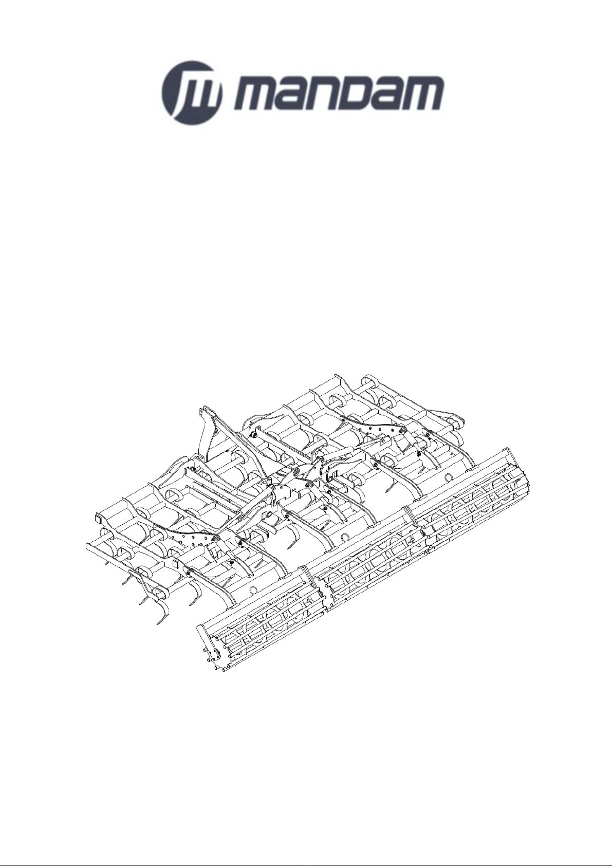
2.1. Design of the SUPER cultivator.........................................................................................7
2.2. Intended use .........................................................................................................................8
3. General safety information .......................................................................................................8
3.1. Proper hitching and unhitching the cultivator from the tractor ........................................9
3.2. Hydraulic system ..................................................................................................................9
3.3. Transport safety on public roads..........................................................................................9
3.4. Residual risk description ....................................................................................................10
3.5. Residual risk assessment ....................................................................................................10
4. Information on operation and use ..........................................................................................10
4.1. Before using the cultivator.................................................................................................12
4.2. Hitching the cultivator with the tractor .............................................................................13
4.3. Operation and adjustment..................................................................................................13
4.3.1. Automatic locking of the machine side extensions ......................................................14
4.3.2. Implement opening sequence ........................................................................................14
4.3.3. SUPER cultivator working depth.................................................................................16
4.4. Rules for transporting the cultivator on public roads and lighting the implement .........19
4.5. Maintenance and lubrication.............................................................................................20
4.6. Screw tightening torque .....................................................................................................20
5. SUPER cultivator maintenance ..............................................................................................21
5.1. Hydraulic system maintenance ..........................................................................................22
6. Replacement procedures .........................................................................................................22
7. SUPER cultivator storage........................................................................................................23
8. SUPER cultivator – spare parts..............................................................................................24

4
1. Introduction
Congratulations on your purchase of the SUPER cultivator.
This instruction manual provides information on the hazards that may occur during use,
cultivator operation, technical data and the most important indications and
recommendations, the knowledge and use of which is a prerequisite for proper operation.
Keep this manual for future reference. Should you have any problems with understanding
any statement in the instruction manual, please contact the manufacturer.
The following mark indicates the guidelines that are important due to safety reasons:
Machine identification
Identification data of the cultivator can be found on the rating plates placed on the load-
bearing frame. The rating plate contains the CE mark, basic information about the
machine and the manufacturer:
The warranty for the cultivator is valid for 12 months from the date of sale.
The warranty card constitutes an integral part of the machine.
Whenever you request any information on spare parts, provide the serial number.
For more information on spare parts,
•please visit our website at: http://mandam.com.pl/parts/
•call us at +48 668 662 289
•e-mail: [email protected]

5
1.1. Safety symbols and inscriptions
CAUTION! Special care must be taken when using the machine in case of
areas marked with special information and warning signs (yellow stickers).
The following symbols and inscriptions can be found on the implement. Secure the
symbols, signs and inscriptions against loss and make sure they are legible at all times. If
lost and illegible, replace the symbols, signs and inscriptions with new ones.
Table 1. Information and warning signs
Safety sign
Meaning of the safety sign
Location on the implement
Read the instruction manual
prior to operating the
implement.
Frame adjacent to the
mounting place of the upper
fastener
Danger of toe or foot crush
Frame adjacent to the
mounting place of the upper
fastener
Keep clear from lift bars
while controlling the lift
Frame adjacent to the
mounting place of the upper
fastener

6
Safety sign
Meaning of the safety sign
Location on the implement
Keep clear from foldable
and moving parts of the
implement
Front part of the central
frame adjacent to side
frames
Do not reach into the
crushing zone if the
elements can move
Central frame adjacent to
side frames
Pressurized fluid – hazard of
bodily injury
Cylinders
Fixing point for transport
belts
Upper part of the drawbar
(upper fastener bolt)
Rear part of the frame:
•rigid frame (adjacent
to the roller depth
adjustment)
•foldable frame
(adjacent to the
cylinder bolt on the
central frame)

7
2. General information
2.1. Design of the SUPER cultivator
Fig. 1 Design of the SUPER cultivator.

8
Table 2. SUPER cultivator types
Cultivator type
Working width [m]
Number of tines
[pcs]
Min. tractor power [hp]
Weight [kg]
SUPER 3.0
3.00
21
80
735
SUPER 4.0 H
4.00
26
100
1556
SUPER 5.0 H
5.00
33
120
1730
SUPER 6.0 H
6.00
37
140
1972
2.2. Intended use
The cultivator is designed to work at depths of 5-15 cm. It is designed to cut the
stubble accurately, mix the plant residues, as well as press and crush the soil evenly. The
SUPER cultivator can be used for post-harvest cultivation as well as for pre-sowing.
The workpieces are 70x12 spring tines mounted on 4 rows of transverse beams so
that stubble undercutting is ensured over the entire working width (depending on the tool
selected) of the implement. The spring tine can be equipped with different coulter types.
CAUTION! The cultivator is designed for agricultural use only – soil
cultivation. Using the implement for tasks that differ from the intended use
shall be regarded as misuse, resulting in loss of warranty.
CAUTION! The manufacturer shall not be liable for any damage arising out of
misuse. Failure to follow the guidelines included in this instruction manual
shall also be regarded as misuse.
3.General safety information
The SUPER universal cultivator can be started, operated and repaired only by
persons familiar with its operation and the attached tractor as well as the rules of safe
operation and maintenance.
The manufacturer shall not be liable for any unauthorised alternation of the cultivator.
Only genuine MANDAM spare parts shall be used during the warranty period.
The cultivator must be operated with all precautionary measures, in particular:
•each time before starting operation check the machine and the tractor whether
their condition guarantees safety during operation and travel,
•minors, disabled or intoxicated persons (under the influence of alcohol or drugs)
must not operate the machine,
•wear work clothes, shoes and gloves during maintenance,
•do not exceed the maximum axle loads, tyre pressure and transport dimensions,
•use only original cotter pins and pins,
•do not approach the cultivator while lifting or lowering,
•do not stay between the tractor and the cultivator when the engine is running,
•start the machine, drive, lift and lower it slowly and smoothly, without sudden
jerks, making sure that nobody stays in the vicinity,
•do not reverse and make U-turns when the implement is lowered to the working
position;
•when making U-turns do not use independent tractor brakes;
•during the operation and travel do not stand on the implement and do not put
additional loads onto it;

9
•while making U-turns, pay due caution if anyone is in the vicinity,
•do not operate the cultivator on slopes with the inclination exceeding 12°,
•any repairs, lubrication or cleaning of working components may be performed as
long as the engine is not running and the cultivator is lowered,
•there is a hazard of head injury when you perform maintenance or replacement of
parts under the implement without adequate protection – wear a hardhat,
•during a break in the work, always lower the implement to the ground and stop the
tractor engine,
•the cultivator is equipped with a mechanical lock which blocks the side frames and
prevents uncontrolled lowering during transport,
•driving and parking the implement on an unstable slope may cause soil slipping,
•store the implement in a manner preventing injury to people and animals.
3.1. Proper hitching and unhitching the cultivator from the
tractor
•Make sure that the machine is hitched to the tractor in accordance with the
instructions, use pins and protect the suspension pins with cotter pins.
•While hitching the tractor with the cultivator, do not stay between the implement
and the tractor;
•The tractor used together with the plough must be fully functional and in good
working order. Do not attach the implement to a tractor with a malfunctioning or
defective hydraulic system.
•Remember to observe the following: balance of the tractor and the cultivator,
tractor steerability and braking performance – the front axle load must not drop
below 20% of the total tractor load – a kit of front weights;
•In the rest position the implement unhitched from the tractor shall maintain a
stable balance.
3.2. Hydraulic system
The hydraulic system operates under high pressure. Take all precautionary measures, in
particular:
•do not connect and disconnect hydraulic hoses when the tractor hydraulic system
is pressurised (hydraulics set to neutral position),
•check regularly the conditions of connections and hydraulic hoses,
•do not use the implement until the hydraulic system is repaired.
3.3. Transport safety on public roads
For transport, fold the side frames into the transport position. Before folding, the machine
must be lifted sufficiently high until the folded side sections do not collide with the
ground. The side frames are automatically locked to prevent their opening. The rollers in
the side frame sections should then be retracted inside the implement by fully retracting
the hydraulic cylinders.
The clearance under the implement during the drive shall be at least 30 cm.
While driving on public roads, it is absolutely mandatory to use lights, an identification
sign for slow-moving vehicles and reflective side lights.
Do not exceed the maximum travel speeds:
–up to 20 km/h on smooth (asphalt) roads,

10
–6-10 km/h on dirt roads or cobblestones,
–up to 5 km/h on bumpy roads.
Adapt the drive speed to the road conditions to prevent the cultivator jumping on the
three-point hitch and to prevent excessive loads on the implement frame and the three-
point hitch.
Maintain particular caution when passing and overtaking and on bends. The maximum
implement width on public roads is 3.0 m.
Do not drive with the implement if the slope is inclined crosswise to the implement by
more than 7°.
Warning! Failure to observe the above rules may pose hazard to the operator
and other people and can lead to the implement damage. The user shall be
liable for any damage caused by failure to observe the rules.
3.4. Residual risk description
Mandam Sp. z o.o. makes every effort to eliminate the risk of accidents. However,
there is some residual risk that may cause an accident. The biggest hazard occurs
when/during:
•using the implement for purposes other no described in the manual,
•operating the implement by people who are underage and do not have licences,
are ill or intoxicated,
•presence of people and animals within the implement operating range,
•precautionary measures are not taken during transport and maneouvering with the
tractor,
•anyone gets between the implement and the tractor while the tractor’s engine is
running,
•during operation when operation guidelines are not followed,
•driving on public roads.
3.5. Residual risk assessment
The residual risk can be minimised by applying the following recommendations:
•operate the implement carefully and without undue haste,
•read the instruction manual carefully,
•keep a safe distance from hazard zones,
•do not stay on the implement and within the implement operating range when the
engine is running,
•perform the maintenance in accordance with safety rules,
•wear safety clothes and a safety helmet while working under the implement;
•prevent the access of unauthorised personnel and especially children to the
implement.
4. Information on operation and use
Before the machine is put into operation for the first time:
•read the instruction manual,
•make sure that the machine is in proper operating condition,
•check the condition of the hydraulic and pneumatic system (replace damaged
components, e.g. pressure hoses),
•make sure that the hydraulic hose quick-connectors of the machine match the
tractor sockets,

11
•check the tightening of bolts and nuts,
•check if the air pressure in tyres is according to the manufacturer’s
recommendations,
•make sure that all components requiring lubrication are lubricated,
•make that the pressure in the tractor wheels is the same on all axles to ensure
smooth operation.
CAUTION! The permissible loads on the axles and tyre load capacities must
not be exceeded. The front axle load may not be less than 20%.
Axle load calculations
Key:
GC – tractor weight,
TP – front axle load for the unhitched tractor,
TT – rear axle load for the unhitched tractor,
GT – total weight of the equipment attached at the back,
GP – total weight of the front-mounted machine,
a – distance between the centre of gravity of the front-mounted equipment and the axle
centre,
b – tractor wheelbase,
c – distance between the rear axle centre and the centre point of the hitching pin of the
rear-mounted implement,
d – distance of the centre of gravity of the agricultural implement from the hitching pins
of the tractor,
x – distance of the centre of gravity from the rear axle (assume 0.45 if the manufacturer
does not provide this parameter).

12
Minimum load at the front in case of a rear-mounted implement:
Actual load on the front axle:
Actual total weight:
Actual load on the rear axle:
4.1. Before using the cultivator
The SUPER universal cultivator is usually delivered for sale in a ready-to-operate
condition. Due to the limitations of the means of transport, it is also possible to deliver it
in a partially disassembled condition – usually by disconnecting the roller.
When preparing the unit for operation for the first time, its components (roller)
must be assembled. To this end, place the cultivator on a flat hard surface in a position
where the roller can be manoeuvred. A lifting device with the load capacity of at least
500 kg must be used for transporting the roller to ensure stability during transport.
Position the arms in the cultivator holders and connect the arms to the roller clamp using
screws (Fig. 2).
Fig. 2 Arm and roller clamp connection.
Prior to operation check the technical condition of the cultivator, in particular that of the

13
working parts and screw connections.
CAUTION! The correct procedure for mounting the rollers in the arm
clamps requires that the screws are tightened evenly diagonally so that the
entire plane of the arm brackets is flush with the plane of the roller clamp
profile. This provides the most secure way of connecting the roller arms to
the machine!
4.2. Hitching the cultivator with the tractor
Tyre pressure in the tractor wheels must comply with the values recommended by the
manufacturer. The lower bars of the three-point hitch should be at the same height,
spaced correspondingly to the spacing of the lower points of the hitch. While attaching
the cultivator to the tractor, the machine must be placed on a hard ground.
Fig. 3 Three-point hitch of the tractor: 1,2 – lower bars, 3 – upper fastener, 4 – left support rail, 5 – right
support rail with adjustable length, 6 – lift arm, 7 – lift shaft
While attaching the cultivator to the tractor, complete the following steps:
•switch the hydraulic system into adjustment position,
•remove lower hitch bolts (if the tractor lift is not equipped with hooks),
•reverse carefully, suspend the implement on the lower bars and secure,
•attach the tractor upper fastener.
•check the operation of cultivator lifting, lowering and the hydraulic system.
4.3. Operation and adjustment
Pre-set the positions of the individual working units in the universal SUPER
cultivator before working in the field. Also level the implement lengthwise with the
tractor upper fastener and laterally with the support rail of the right lower bar. Then,
make the first work passage to set the optimum working speed and to correct the
adjustment based on an assessment of the correct operation of the individual units. The
operating speed should be 8 – 12 km/h. In a well-adjusted machine, the frame must be
parallel to the ground and all working units must be equally recessed in the soil over the
entire working width.

14
4.3.1. Automatic locking of the machine side extensions
On machines with folding sections, an automatic lock of side extensions is available that
requires no additional operation. The lock uses a mechanism consisting of a cylinder and
a hook (Fig. 4).
Fig. 4 Main frame with automatic side extensions locking mechanism
4.3.2. Implement opening sequence
Before unfolding the folding side the extensions of the machine, learn the opening
sequence to perform this operation correctly.
1. First, raise the implement as much as possible to be able to fold it correctly,
avoiding the risk of the folding arms snagging on the ground during movement
(Fig. 5).
2. Next, fold the implement side extensions hydraulically into the “closed” position
to ensure that the side extension lock mechanism will unlock and allow the
implement arms to be opened at a later stage. This operation is necessary each
time the arms are opened (Fig. 5).

15
Fig. 5 Implement opening sequence: 1- raise the implement up to the maximum, 2- fold the side
extensions into the “closed” position.
3. Then, after making sure that the hook of the hydraulic side extension lock
mechanism allows the machine side extensions to be unlocked, proceed to open
them fully (Fig. 6).
Fig. 6 Implement opening sequence: 3- release the hook of the hydraulic side extension lock mechanism,
4- open the implement side extensions.

16
4. When opening the implement’s side extension arms, make sure that the ends of
the arms are at the correct height to prevent them from snagging on the ground
(Fig. 7).
Fig. 7 Implement opening sequence: open the implement paying particular attention to the height of the
arm ends from the ground.
5. To complete the opening sequence of the implement side extensions, wait until
the hydraulic mechanism opens the arms to their end position. Do not interrupt
the opening process of the arm side extensions without ensuring that they are
fully open (Fig. 8).
Fig. 8 View of the implement at the completion of the side extension opening sequence. The implement
arms are fully open.
4.3.3. SUPER cultivator working depth
The working depth is determined by the position of the roller the arms of which are
adjustable by the cylinders. In order to maintain a constant stable position of the roller
(working depth) during operation, latches are fitted on the cylinder piston (Fig. 10).

17
Initially, set the roller and the wheels above the lower edge of the spring tines at the
height corresponding to the approximate working depth, and correct the position during
operation, after taking into account the roller recess. The maximum permissible working
depth is 15 cm.
Fig. 9 Hydraulic roller depth adjustment
Fig. 10 Cylinder with latches attached to the piston rod to adjust the working depth
The working depth of the implement is set using latches at the piston rod. As more latches
are folded, the operation of the implement becomes shallower. In case none of the latches
are installed, the implement operates at maximum working depth. Fig. 11 and Fig. 12
show the correct and incorrect way of installing consecutive latch plates on the cylinder.

18
Fig. 11 Correct way to place the first (1) latch on the cylinder piston rod to adjust the implement working
depth.
Fig. 12 Latches fitted incorrectly on the cylinder piston rod. If the latches are partially omitted from the
cylinder, the forces acting on the piston rod are not evenly distributed and may cause the piston rod to
buckle, resulting in damage to the entire piston assembly. This type of adjustment is unacceptable!
The cultivator can also work without rollers, but the depth can be maintained by the
tractor’s hydraulic adjustment and the soil remains loosened.

19
4.4. Rules for transporting the cultivator on public roads and
lighting the implement
According to the road traffic safety regulations (Regulation of the Minister of
Infrastructure of 31 December 2002, Journal of Laws No. 32 of 2002, item 262) – an
implement unit consisting of an agricultural tractor and an agricultural implement hitched
with the same must meet the requirements identical to those applying to the tractor
itself.
The implements must be equipped with:
- triangular board for slow vehicles;
- two boards facing front with a white parking light and a white retroreflector;
- two boards facing rear with composite lamp and a red retroreflector. The plates should
be painted in diagonal white and red stripes.
After fixing the plates, connect the electrical cables of the light and signalling device to
the tractor’s electrical socket.
The manufacturer does not supply warning plates as standard equipment for the machine.
Warning plates are commercially available.
Always adapt your driving style to the road conditions to avoid accidents and damage to
the driving system. Take into account your own skills and traffic intensity, visibility and
weather conditions.
Fig. 13 Rear lighting assemblies and their location.
Clean the implement from soil residues and check the lights before transporting it. After
lifting the machine, check the ground clearance under the lowest working elements, which
should be at least 25 cm. The permissible transport speed of the tractor and machine is
15 km/h. It should be 10 km/h in case of poor road surface and 5 km/h on dirt roads.

20
Special care must be taken when passing and overtaking other vehicles, bypassing
obstacles and crossing large areas of uneven ground and dirt roads.
4.5. Maintenance and lubrication
•Clean the disc harrow from soil after each use and inspect the parts and assemblies.
Otherwise, there may be a problem with the folding of the machine if the rollers are
clogged with soil and there is an additional load!
•After the first 4 hours of operation, re-tighten all bolts and periodically check them
for tightness. Failure to do so will exacerbate play and backlash and result in damage
to the implement.
•Lubricate the lubrication points on the hinge pins daily during the machine’s service
life. Lubricate the bearings of the tubular roller and the levelling discs every 25 operating
hours (not applicable to disc maintenance-free bearings – these bearings do not require
maintenance or lubrication).
•Use thread adhesive and only genuine screws and nuts when replacing worn parts.
•Always remember to tighten the screwed joints properly.
CAUTION! Periodic lubrication guarantees the long service life of the machine.
The long service life and efficiency of a machine depends to a large extent on regular
lubrication. Use mineral greases for lubrication. Clean the lubrication points thoroughly
before pressing or applying grease.
CAUTION! It is forbidden to work on a damaged machine caused by any
event resulting in a broken, or deformed frame, roller or other assembly
of the machine!
4.6. Screw tightening torque
Screws, bolts and nuts should be tightened in the machine with the appropriate torque
depending on the strength class of the bolt and its thread size and pitch. The
corresponding torque values for tightening them are shown in Table 3.
Table of contents
Other Mandam Farm Equipment manuals

Mandam
Mandam MCH Series User manual

Mandam
Mandam ORKAN 3+ User manual

Mandam
Mandam RHINO User manual

Mandam
Mandam MWC Series User manual

Mandam
Mandam ORKAN VARIO Series User manual

Mandam
Mandam Hybro 3,0 User manual

Mandam
Mandam KNIFE ROLLER 3.0 User manual

Mandam
Mandam MGP Series User manual

Mandam
Mandam SAL DISC HARROW User manual

Mandam
Mandam MBS User manual