LIT-136 PAGE 2 of 4
Maintenance
The only basic maintenance for the
GRS Monarch Handpiece is keeping
it clean on the inside. Problems will
occur if oil or moisture gets into
the handpiece, especially on the
piston. If you notice a loss of power
or erratic performance, the FIRST
THING to check is to make sure
the RECEIVER (chuck) IS TIGHT IN
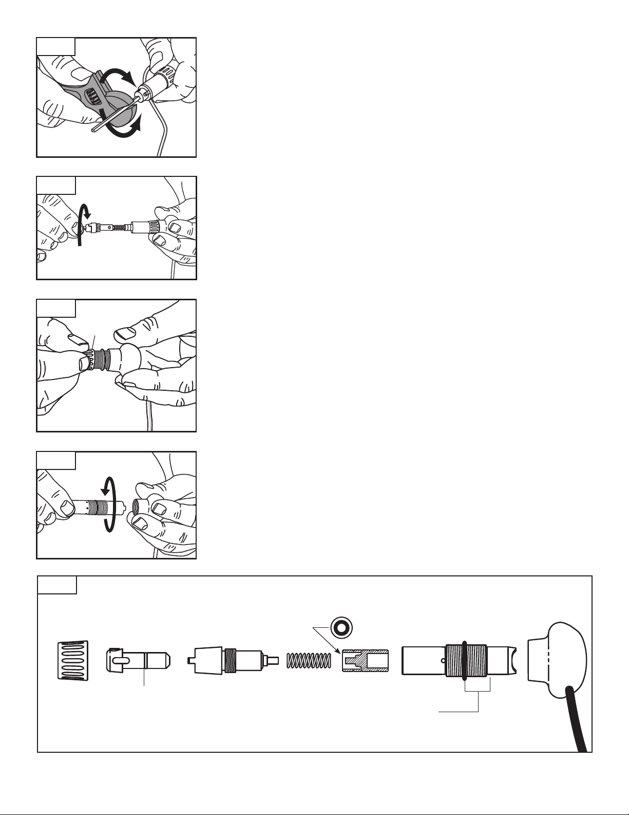
THE HANDPIECE BODY. Using a
crescent wrench or pliers with a graver
inserted in the QC Holder, gently
tighten receiver clockwise (FIG.3) If
erratic performance continues, then
disassemble and clean the handpiece.
To disassemble the handpiece, use
the crescent wrench or pliers to
grip the graver (FIG. 3) and turn it
counterclockwise to loosen the chuck
retainer. After loosening, turn the
chuck retainer out with your finger tips
(FIG. 4). As you pull out the chuck,
there will be a spring and piston.
Loosen the locking ring and remove
it (FIG. 5). Grip the knob and turn the
handpiece body counter-clockwise
until it is out of the knob body (FIG. 6).
Now, with the handpiece
disassembled, clean the parts with a
NON-residue solvent like denatured
alcohol. Make sure the holes in the
handpiece body are clear from dirt
and debris. DO NOT get moisture
down the air hose. If this happens you
will need to clear and dry it before
reassembly.
Before reassembly, make sure every
thing is completely dry. DO NOT
OIL INSIDE THE HANDPIECE. NO
lubricant is required. Lubricant will
actually decrease performance!
Reassembly Note:
There is an O-ring inside the knob
that makes getting the handpiece
body to thread a little dicult when
reassembling. Use a very small
amount of synthetic lube or non-stick
grease and create a thin film around
the OUTSIDE of the shaft between the
threads and the end (see call out in
FIG. 7).
NOTE: Do NOT use petroleum based
oils - USE ONLY Synthetic oils. Fossil
oils can damage the O-rings.
See “Adjusting the Handpiece” on
page 1 for adjusting graver and hose
position.
VERY LIGHT
synthetic grease lm
END VIEW
Round ANVIL head toward spring
CROSS
SECTION VIEW
QUICK CHANGE HOLDER HINT
Synthetic Lube or non-stick grease on
the shaft of a quick change holder will
make them easier to slip in and out.
FIG. 7
FIG. 6
LOCKING
RING
FIG. 5
FIG. 4
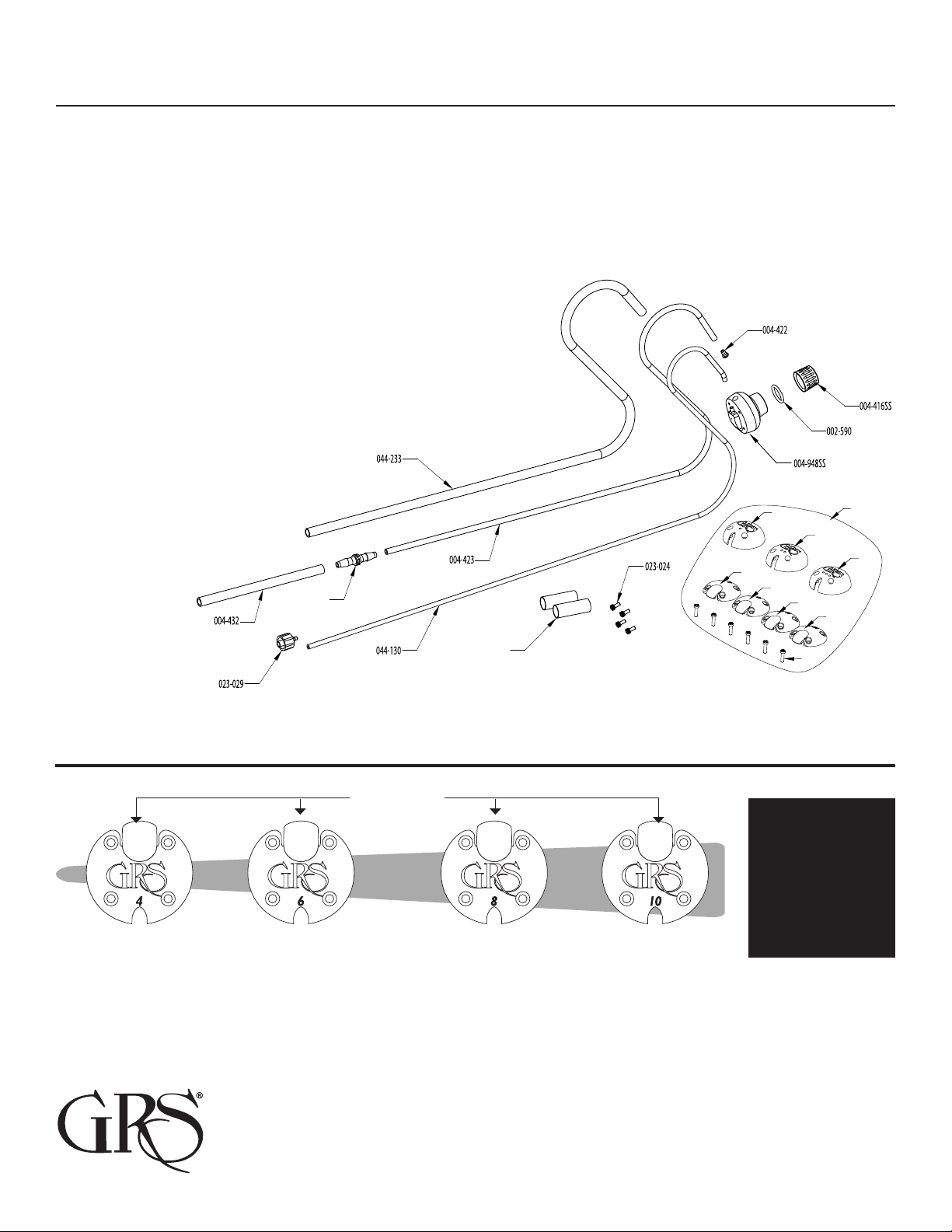
Part # Description
002-950 8-32 X .13
002-605 Allen Wrench
002-590 O-Ring 1/2" ID X 1/16" Wide
004-803 Quick Change Chuck (complete with set screw)
004-415SS Handle Knob
004-416SS Locking Nut
004-417 Handpiece Body
Part # Description
004-929-V2 Chuck Receiver
004-422 Air Hose Retainer
004-423 Air Hose - 1/8" dia. X 38"
004-424 Spring
004-927-V2 Piston / Hammer
022-308 O-Ring 8 mm ID X 1 mm Wide
022-072 Tube Coupling
004-432 Urethane Tubing .170" I.D. X 10"
004-803 (INCLUDES SET SCREW)
004-424
004-432
004-927-V2
004-929-V2
022-308 004-417
002-590
004-415SS
004-423
004-422
022-072
004-416SS
002-590
002-605
002-950
LOOSEN
TURN COUNTERCLOCKWISE
TIGHTEN
TURN CLOCKWISE
FIG. 3