GRUNDFOS ALLDOS Suction Lines 531 User manual

15.750047-V2.0
Suction Lines 531
Operation Manual
Read this manual completely and keep it!

SL 531 en
215.750047-V2.0
Imprint
Suction Lines 531
Operation Manual
Version 2.0
Publisher
ALLDOS Eichler GmbH
Reetzstraße 85 • 76327 Pfinztal (Söllingen)
Postfach 1160 • 76317 Pfinztal
Germany
Tel. +49 72 40 61-0 / Fax. +49 72 40 61-211
Mail: alldos.d[email protected]
Internet: www.grundfosalldos.com
© 2008 by ALLDOS Eichler GmbH
Subject to change.

SL 531 en
V2.0 III
Content
Imprint............................................................................................. 2
1 General ........................................................................................... 4
1.1 General Information .........................................................................4
1.2 Using this document ........................................................................4
1.3 Guarantee ........................................................................................4
2 Safety ............................................................................................. 5
2.1 Using the Component ......................................................................5
2.2 Obligations of the owner ..................................................................5
2.3 Avoidance of danger ........................................................................5
3 General description ........................................................................ 6
3.1 Function ...........................................................................................6
3.2 Structure ..........................................................................................6
4 Installation ...................................................................................... 6
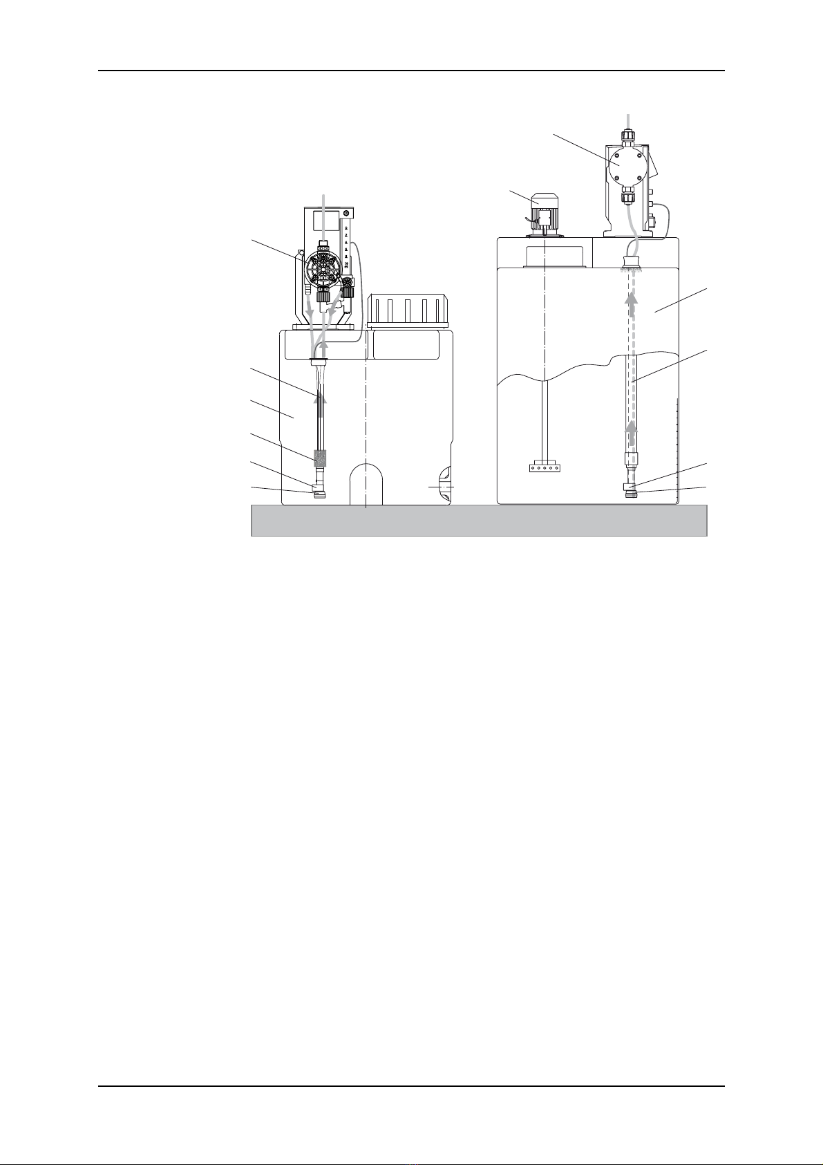
4.1 Installation (examples) .....................................................................7
4.2 Installing the Suction Line ................................................................8
4.2.1 Fixing the suction line to the reservoir/tank ...................................9
4.2.2 Connecting the suction line to the pump .....................................10
5 Empty Signal and Pre-Empty/ Empty Signal ................................ 11
5.1 Empty signal ..................................................................................11
5.2 Empty/Pre-empty signal ................................................................11
5.3 Reed Switch - Technical Data .......................................................12
5.4 Connecting the Empty or Pre-Empty/Empty signal .......................12
5.4.1 Round plug (DDI 222) ..................................................................12
5.4.2 Flat plug (DDI 209, AR electronics) .............................................12
5.4.3 Cable assignment of plugs ..........................................................12
6 Maintenance ................................................................................. 13
6.1 Cleaning ........................................................................................13

SL 531 en
415.750047-V2.0
1 General
1.1 General Information
This technical information contains all the information required for starting up and
handling the described suction lines.
If you require further information or if any problems arise that are not discussed in detail in
this document, contact Grundfos Alldos directly for more information.
1.2 Using this document
The safety instructions WARNING,CAUTION and NOTE have the following meanings:
!
Warning
Risk of accidents and injury!
Attention
Risk of malfunction or damage to the device!
Note
There is an exceptional feature.
1.3 Guarantee
A guarantee claim in the sense of our general conditions of sale and delivery can only be
recognised if:
• The component has been used according to the information in this technical
information,
• The component is not subjected to improper use,
• Installation, service, and repairs are only carried out by authorised and qualified
personnel,
• Only original spare parts are used for repairs
The safety instructions specified in this document must be observed at all times.

SL 531 en Safety
V2.0 5
2 Safety
The component has left the factory in a safe error-free state.
In order to maintain this state and ensure safe operation, the user most observe the
instructions and warning notes provided in this technical information.
If safe operation is no longer possible, the component must be shut down and secured
against unintentional operation. This is the case:
• If the component is visibly damaged
• If the component no longer seems operational
• Following long periods of storage under unfavourable conditions
2.1 Using the Component
The suction line systems described here are used in connection with Grundfos Alldos
dosing pumps.
Possible applications include:
• Installation in Grundfos Alldos dosing tanks
• Installation in transport tanks or canisters
• Installation in plant-specific dosing tanks
2.2 Obligations of the owner
The owner of the plant is responsible for
• Training of operating personnel
• Arranging regular maintenance.
!
Warning
Other applications are considered as non-approved, and are not permissible.
Grundfos Alldos accepts no liability for any damage resulting from incorrect use.
2.3 Avoidance of danger
!
Warning
When dosing dangerous media, observe the corresponding safety precautions!
!
Warning
When working with connections and suction lines:
Always wear protective clothing (safety glasses and gloves)!
Attention
Please observe the chemical resistance of dosing media with regard to materials.

SL 531 en
615.750047-V2.0
3 General description
3.1 Function
The suction line is used to transport the dosing medium from the tank to the pump. All
suction lines consist of a foot valve with a sieve filter and a flexible or fixed line for
connecting the pump.
Suction lines with a reed contact are used for connecting to pumps with Empty or Empty/
Pre-Empty electronic signals.
3.2 Structure
Grundfos Alldos suction line systems for installation in tanks or canisters consist of the
following components:
•Line
• Fixed: Hose with fixed protective tube or
• Flexible: Hose without protective tube
• Foot valve
• with sieve filter
or
• Foot valve (for Empty or Empty/Pre-Empty signal)
• with reed contact(s) in the valve body
• with float including magnetic core
• with round plug for connecting to DDI 222 or flat plug for connecting to DDI 209 or
AR electronics
• with sieve filter
• Fixing the suction line to the reservoir/tank
4 Installation
!
Warning
The suction line must only be installed by authorised and qualified persons!
!
Warning
When dosing dangerous media, observe the corresponding safety precautions!
!
Warning
When working with connections and suction lines:
Always wear protective clothing (safety glasses and gloves)!

SL 531 en Installation
V2.0 7
4.1 Installation (examples)
1 Dosing pump with electronic control (here DDI 209 with Plus3system)
2 Flexible suction line (hose without protective tube) with reed contact for empty signals and PE
stopper for tank installation
3 Tank
4Sinker
5 Float
6 Foot valve with sieve filter
7Agitator
8 Dosing pump with electronic control (here DDI 222)
9 Fixed suction line (hose with fixed protective tube, reed contacts for Pre-Empty/Empty signal and
Empty signal, and knurled nut for tank installation)
7
8
3
5
9
1
4
6
3
2
5
6

SL 531 en
815.750047-V2.0
4.2 Installing the Suction Line
!
Warning
When dosing dangerous media, observe the corresponding safety precautions!
!
Warning
When working with connections and suction lines:
Always wear protective clothing (safety glasses and gloves)!
1. Attach the suction line so that the foot valve remains approximately 5 to 10 mm above
the bottom of the tank or the possible level of sedimentation.
Attention
Consult the technical information for the dosing pump.
2. Connect the suction line to the pump dosing head.
3. If the suction line has a Empty or Pre-Empty/Empty signal, insert the plug for the
signal line into the designated socket (see the pump instructions).
4. Guide the deaeration hose of the pump (if applicable) into the tank through the drilled
hole in the tank lid.
Attention
Do not immerse the deaeration line in the dosing medium!

SL 531 en Installation
V2.0 9
4.2.1 Fixing the suction line to the reservoir/tank
Note
Drill a hole with Ø45 mm for fixing the suction line to the container (A, B and C).
Screw cap for canister installation
1 Plug (Empty or Pre-Empty/Empty signal)
2 Signal line
3 Float endpoint
4 Closing contact (N.O. = normally opened)
5 Opening contact (N.C. = normally closed)
6 Connection (removed on the pump suction side)
7 Flexible suction line (hose without protective
tube)
8 Float
9 Foot valve with sieve filter
Variants
A Flexible suction line
PE stoppers for tank installation
B Fixed suction line
PE stoppers for tank installation
C Fixed suction line / operation with agitator
Knurled nuts for tank installation
D Fixed suction line
Screw cap for canister installation, in
different sizes acc. to DIN 6131,
Part 1, see below.
E Fixed suction line
Reservoir adapter with coarse thread
S 70x6 or G2“
Ø45
5
4
8
3
9
6
2
A
Ø45 Ø45
BC
DE
7
S 70x6
1
G2’’
SK 5 -12
SK 20-60
SK 60 A
Abbreviation
in acc. with DIN 6131,
part 1
d4
(mm)
SK 5-12 56
SK 20-60 75
SK 60A 84,5
d
4

SL 531 en
10 15.750047-V2.0
4.2.2 Connecting the suction line to the pump
Connect the suction line to the suction valve on the pump. To do this, use the connection
set supplied with the pump.
Suction lines with integrated Empty or Pre-Empty/Empty signals have a reed contact float
switch. The signal cable plug for transferring the Empty or Pre-Empty/Empty signal is
connected to socket 5 on the pump (see the section "Empty Signal and Empty/Pre-Empty
Signal).
G3/8“ - G5/8“ adapter
Suction lines with G5/8“ dimensions can also be used for pumps of size G3/8“ (DN4). To
enable this, the adapter must be screwed between the suction line and the suction valve
using an O-ring. Please order the required connection for the suction line separately.
1 Adapter
2O-ring
G3/8“ - G5/8“ adapter O-ring
Material Order No. Material Order No.
PVC 91834125 (10.4277-400) EPDM 91835552 (52.105-1)
1.4571 91834126 (10.4277-401) Viton 91835553 (52.105-2)
PVDF 91834127 (10.4277-402) PTFE 91835627 (52.344)
PP 91836488 (10.4277-404)
G5/8"
G3/8"
1
2

SL 531 en Empty Signal and Pre-Empty/ Empty Signal
V2.0 11
5 Empty Signal and Pre-Empty/ Empty Signal
The Empty signal is used to switch off the pump if the tank is empty. The Pre-Empty
signal issues a warning when the tank is nearly empty. For more information, also see the
instructions for the pump electronics.
The (reed) contact for this signal is triggered by the float (with magnetic core), which
slides past the valve body as the level of dosing medium in the tank drops.
5.1 Empty signal
In the Empty signal version, the factory setting for the contact is “Closing“ (N.O. =
normally opened), see A. The symbol for this is located on the top of the float.
The contact type can be changed to “Opener“ (N.C.= normally closed). With this type of
contact, a cable break leads to an empty signal (fail-safe).
To change the contact type to N.C.:
1. Pull the float outwards to the side,
2. Rotate the float by 180° and replace it (with the symbol for at the top).
1 Closing contact (N.O. = normally open)
2 Opening contact (N.C. = normally closed)
3 Floater endpoint
4 Float
5 Foot valve with sieve filter
5.2 Empty/Pre-empty signal
When you order the suction line, specify the contact type for the Pre-Empty/Empty signal.
You define whether the required contact type is a "Closer" or an "Opener".
In this version, there is no float endpoint.
1 Float
2 Foot valve with sieve filter
Note
In this version, you cannot subsequently change the contact type by rotating the
float!
2
1
33
4
5
5
1
2
180°
4
4
4
4
AB
2
1

SL 531 en
12 15.750047-V2.0
5.3 Reed Switch - Technical Data
5.4 Connecting the Empty or Pre-Empty/Empty signal
For suction lines with an Empty or Empty/Pre-Empty signal, the signal cable plug is
connected to the corresponding socket of the pump electronics (for more information, see
the instructions for the pump electronics).
5.4.1 Round plug (DDI 222)
To connect the empty/pre-empty signal: Connect to socket 5.
The colour coding for the round plugs and cables, and the pin assignment is as follows:
5.4.2 Flat plug (DDI 209, AR electronics)
The flat plug is connected to socket 5.
The cables and flat plugs are colour-coded as follows:
5.4.3 Cable assignment of plugs
Max. switching voltage 48 V
Max. switching current 0.5 A
Max. switching capacity 10 W / VA
Contact type Closer or opener
Degree of protection IP67 (IEC 529)
Temperature range -25°C....+65°C
Colour coding Socket 5 Used for
Plug Cables Pin Assignment Empty signal Pre-empty signal
Empty
signal
Pre-empty signal/
Empty signal 1Pre-empty
signal —x
Blue Brown Brown 2 Empty signal x —
White White Green 3 GND x x
Brown — White
Coding
No. Empty signal Pre-empty signal/
Empty signal
1White Brown
2— White
3 Brown Green
1
2
3
1
2
3
1
2
3
1
2
3
Empty signal
Empty/
Pre-empty
signal
Empty/
Pre-empty
signal
Closer Closer/Closer Opener/Opener
BN
GN
WH WH
BN BN
GN WH

SL 531 en Maintenance
V2.0 13
6 Maintenance
!
Warning
Maintenance must only be performed by authorised and qualified personnel!
!
Warning
When dosing dangerous media, observe the corresponding safety precautions!
!
Warning
When working with connections and suction lines:
Always wear protective clothing (safety glasses and gloves)!
6.1 Cleaning
Clean the sieve filter
• if a blockage occurs
• if you notice a drop in the suction power
Cleaning the sieve filter
1. Shut down the dosing system.
2. For suction lines with empty or empty/pre-empty signals, remove the plug for the
signal line from the pump (socket 5).
3. Unscrew the suction line from the dosing head, if applicable, remove the deaeration
line from the dosing head.
4. Remove the suction line from the container.
Attention
Safely dispose of any chemical waste in the suction line!
5. Dismantle the sieve filter (2).
6. Clean the sieve filter.
7. Replace the sieve filter.
8. Attach the suction line to the tank.
9. Screw the suction line onto the dosing head and, if applicable, connect the deaeration
line to the dosing head.
10. For suction lines with empty or empty/pre-empty signals, insert the plug for the signal
line (into socket 5).
1 Float
2 Foot valve with sieve filter
2
1

SL 531 en
14 15.750047-V2.0

SL 531 en Maintenance
V2.0 15

SL 531 en
16 15.750047-V2.0
Table of contents
Other GRUNDFOS ALLDOS Industrial Equipment manuals