Grundfos CIM 200 User manual

Modbus for Dedicated Controls
CIM 200 Modbus RTU
CIM 250 GSM/GPRS
CIM 500 Ethernet for Modbus TCP
Functional profile and user manual
GRUNDFOS INSTRUCTIONS
Pumpland.ru

English (GB)
2
English (GB) Functional profile and user manual
Original functional profile and user manual.
CONTENTS
Page
1. Symbols used in this document
1. Symbols used in this document 2
2. Introduction 3
2.1 About this functional profile 3
2.2 Assumptions 3
2.3 Definitions and abbreviations 3
3. System description 4
3.1 Modbus 4
3.2 Modbus RTU (CIM 200) 4
3.3 Modbus GSM/GPRS (CIM 250) 4
3.4 Modbus TCP (CIM 500) 4
4. Specifications 5
4.1 CIM module 5
4.2 CIM 200 Modbus RTU 5
4.3 CIM 250 GSM/GPRS 6
4.4 CIM 500 Modbus TCP 6
5. Modbus RTU, CIM 200 setup 7
5.1 Setting the Modbus transmission speed 7
5.2 Setting the parity 8
5.3 Modbus address selection 8
5.4 Termination resistor 8
5.5 Status LEDs 9
6. Modbus GSM/GPRS, CIM 250 setup 10
6.1 Installation 10
6.2 Status LEDs 11
7. Modbus TCP, CIM 500 setup 12
7.1 Connecting the Ethernet cable 12
7.2 Setting the Industrial Ethernet protocol 12
7.3 Setting up the IP addresses 12
7.4 Establish connection to the Web server 13
7.5 Status LEDs 13
7.6 DATA and LINK LEDs 13
8. Modbus function code overview 14
9. Modbus register overview 15
9.1 Register block overview 15
9.2 CIM configuration register block 16
9.3 CIM status register block 18
9.4 GSM real time clock 18
9.5 Pit control and configuration register block 19
9.6 Pit status register block 24
9.7 Pit data register block 32
9.8 Pump 1 register block 34
9.9 Pump 2 register block 36
9.10 Pump 3 register block 38
9.11 Pump 4 register block 40
9.12 Pump 5 register block 42
9.13 Pump 6 register block 44
9.14 Alarm simulation register block 46
9.15 User register block 46
9.16 Name string register block 46
9.17 Hour log register block 47
9.18 Event log register block 48
9.19 Data log index register block 49
9.20 Data log series register block 50
10. Modbus RTU commissioning, step-by-step guides 51
10.1 Hardware setup (CIM 200) 51
10.2 Hardware setup (CIM 250 GSM call-up) 51
10.3 Hardware setup (CIM 250 GPRS connection) 51
10.4 Modbus TCP communication setup (CIM 500) 52
11. Detailed descriptions of functionality 53
11.1 SCADA PIN code protection 53
11.2 Reading the event log 53
11.3 Reading the configurable data log series 54
11.4 Separation of reads and writes 56
11.5 Control bit acknowledgement 56
11.6 GSM call-up connection 57
11.7 GSM call-back connection 57
11.8 Use of SMS messages 58
11.9 GPRS connection 58
11.10 Interlocking 61
11.11 Real-time clock 62
11.12 Event simulation 62
11.13 Alarms and warnings 63
12. Modbus RTU telegram examples 67
12.1 Modbus telegram overview 67
12.2 Read holding registers (0x03) 67
12.3 Read input registers (0x04) 67
12.4 Write single register (0x06) 68
12.5 Write multiple registers (0x10) 68
12.6 Diagnostics (0x08) 69
12.7 Diagnostics register interpretation 69
13. Application example 70
13.1 Adaptation of pit graphics to installation values 71
13.2 Main status 71
14. Modbus function code overview 76
15. Modbus telegram examples 77
15.1 Diagnostics: return query data 77
15.2 Reading the CIM configuration register block 77
15.3 Reading the pit water level 77
15.4 Reading the pit alarms 78
15.5 Setting pit auto mode 78
15.6 Interlocking the pit 79
16. Fault finding 80
16.1 CIM 200 80
16.2 CIM 250 82
16.3 CIM 500 84
17. Modbus RTU rotary switch addresses 86
Warning
If these safety instructions are not observed, it may
result in personal injury.
Caution
If these safety instructions are not observed, it may
result in malfunction or damage to the equipment.
Note
Notes or instructions that make the job easier and
ensure safe operation.
Pumpland.ru

English (GB)
3
2. Introduction
2.1 About this functional profile
This functional profile describes the following modules/units:
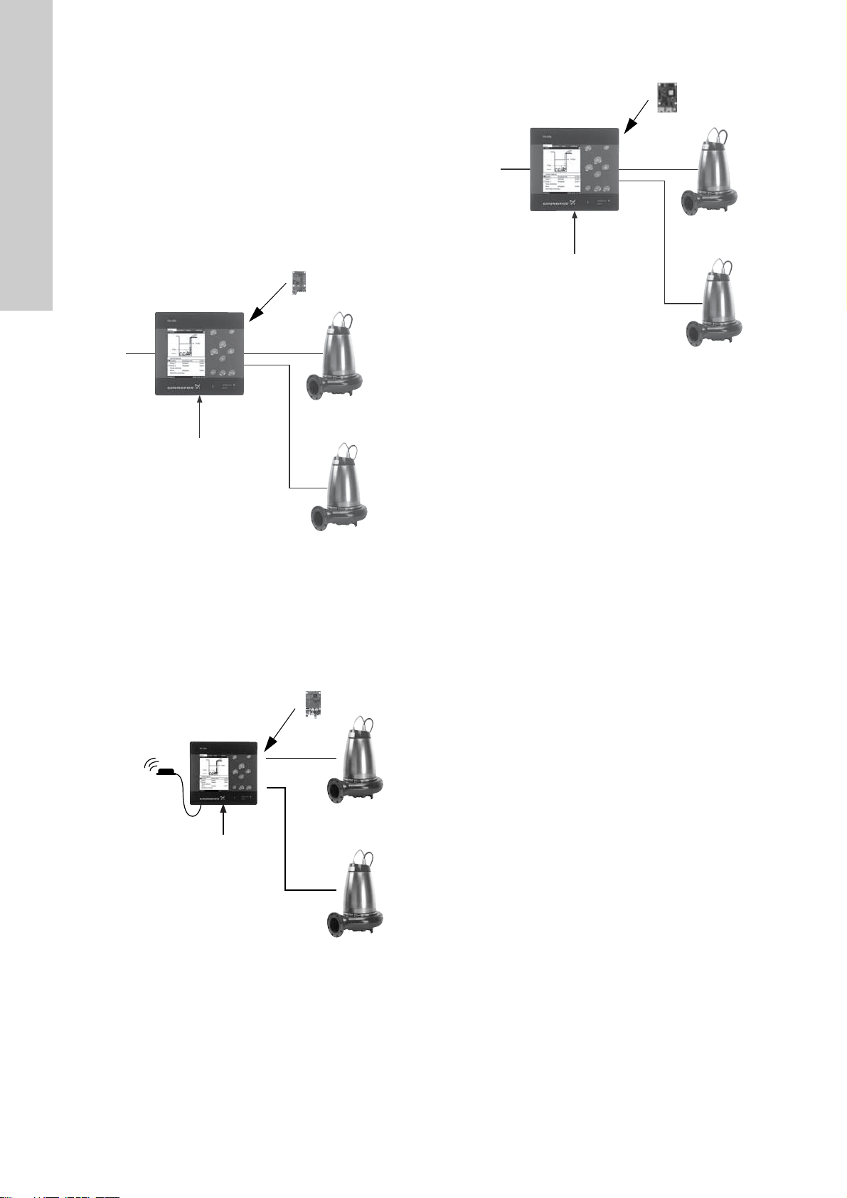
• CIM 200 Modbus RTU
• CIM250 Modbus GSM/GPRS
• CIM 500 Modbus Ethernet for Modbus TCP
This functional profile applies to the following Grundfos products:
• Grundfos Dedicated Controls 361
• Grundfos Dedicated Controls 362.
In the following, the two supported controllers are referred to as
CU 36X.
The data in this document are subject to change without prior
notice. Grundfos cannot be held responsible for any problems
caused directly or indirectly by using information in this functional
profile.
2.2 Assumptions
This functional profile assumes that the reader is familiar with
commissioning and programming of Modbus devices. The reader
should also have some basic knowledge of the Modbus protocol
and technical specifications.
It is also assumed that an existing Modbus network with a
Modbus master is present.
2.3 Definitions and abbreviations
0b Prefix for binary number
0x Prefix for hexadecimal number
3G Third-generation mobile telephony network
4G Fourth-generation mobile telephony network
ARP Address Resolution Protocol. Translates IP
addresses into MAC addresses.
Auto-MDIX Ensures that both crossover cable types and
non-crossover cable types can be used.
CAT5 Ethernet cable type with four twisted pairs of
wires
CAT5e Enhanced CAT5 cable with better
performance
CAT6 Cable with very high performance
CIM Communication Interface Module
CRC Cyclic Redundancy Check. Adata error
detection method.
CSD
Circuit Switched Data. Connection is
established via a fixed connection (a physical
circuit or a reserved data channel).
CU 36X Grundfos control unit for Dedicated Controls
(CU 361 and CU 362)
DHCP
Dynamic Host Configuration Protocol. Used to
configure network devices so that they can
communicate on an IP network.
DNS Domain Name System. Used to resolve host
names to IP addresses.
GENIbus Proprietary Grundfos fieldbus standard
GENIpro Proprietary Grundfos fieldbus protocol
GPRS
General Packet Radio Service. Technology
for TCP/IP communication and internet
access via GSM.
Grundfos GO
A Grundfos handheld remote control device
for controlling Grundfos products via infrared
or radio. Based on smart phone technology.
GSM Global System for Mobile communications
H Head (pressure)
HTTP
Hyper Text Transfer Protocol. The protocol
commonly used to navigate the world wide
web.
IANA Internet Assigned Numbers Authority
IP Internet Protocol
LED Light-Emitting Diode
MAC Media Access Control. Unique network
address for a piece of hardware.
Modbus
A serial communications protocol commonly
used in industry and building automation
systems
Modbus RTU
Modbus is a fieldbus used worldwide. The
RTU version is used for wired networks (CIM
200) and for call-up connections over
telephone networks (CIM 250).
Modbus TCP
Modbus is a fieldbus used worldwide. The
TCP version is adapted for use as an
application protocol on TCP/IP using either
GPRS (CIM 250) or Ethernet (CIM 500) as
basis.
MP 204 Grundfos motor protector
PIN Personal Identification Number. For SIM
cards.
Ping
Packet InterNet Groper. A software utility that
tests the connectivity between two TCP/IP
hosts.
PUK Personal Unblocking Key. For SIM cards.
QFlowrate
R100 Grundfos handheld infrared remote control
SELV Separated or Safety Extra-Low Voltage
SELV-E Separated or Safety Extra-Low Voltage with
earth connection
SIM Subscriber Identity Module. SIM card.
SMA SubMiniature version A. Coaxial radio signal
cable connection standard.
SMTP Simple Mail Transfer Protocol
SNTP
Simple Network Time Protocol. Used for
clocks synchronization between computer
systems.
TCP
Transmission Control Protocol. Protocol for
Internet communication and Industrial
Ethernet communication.
TCP/IP Transmission Control Protocol/Internet
Protocol. Protocol for Internet communication.
Transmission
speed Bits transferred per second, bits/s
URL Uniform Resource Locator. The IP address
used to connect to a server.
UTC
Coordinated Universal Time. The primary
time standard by which the world regulates
clocks and time.
UTF-8 Unicode Transformation Format. Character
encoding.
VPN
Virtual Private Network.
A network using the Internet to connect
nodes. These systems use encryption and
other security mechanisms to ensure that only
authorised users can access the network and
that the data cannot be intercepted.
Pumpland.ru

English (GB)
4
3. System description
3.1 Modbus
The Grundfos Dedicated Controls CU 36X control unit is
connected to up to six Grundfos wastewater pumps. It offers
status information as well as control and monitoring of a
wastewater pit via a user-friendly control panel with display.
The CIM 200/250/500 is an add-on communication module to be
fitted in the CU 36X, using a 10-pin connection. This enables
communication with a PLC, SCADA system, etc.
Via the Modbus RTU connection, it is possible to control the
pumps and read status, measured values, logs, etc.
3.2 Modbus RTU (CIM 200)
Fig. 1 CIM 200 solution for Dedicated Controls. Up to six
pumps can be connected to CU 36X
3.3 Modbus GSM/GPRS (CIM 250)
The CIM 250 is an add-on communication module to be fitted in
the CU 36X, using a 10-pin connection. This enables GSM/GPRS
communication with a PLC, SCADA system, mobile phone, etc.
Via the GSM/GPRS connection, it is possible to control the
pumps and read status, measured values, logs, etc.
Fig. 2 CIM 250 solution for Dedicated Controls. Up to six
pumps can be connected to CU 36X
3.4 Modbus TCP (CIM 500)
Fig. 3 CIM 500 solution for Dedicated Controls. Up to six
pumps can be connected to CU 36X
TM04 3409 4408TM04 4903 2209
Sensor input
Modbus RTU
CU 36X
1 2 345 67
8
9
CIM 200
Sensor input
GSM/GPRS CU 361
CU 36X
1
23 45
6
CIM 250
TM04 3409 4408
Sensor input
Modbus TCP
CU 36X CIM 500
Pumpland.ru

English (GB)
5
4. Specifications
4.1 CIM module
4.2 CIM 200 Modbus RTU
The table below provides an overview of the specifications for the
Grundfos CIM 200. For further details, please refer to the specific
sections of this functional profile.
* Can only be set via software.
General data Description Comments
Ambient humidity 30 % to 95 % Relative, non-condensing.
Operating temperature -20 °C to +45 °C
Storage temperature -25 °C to +70 °C
Battery, lithium-ion The battery will only be charged if the
battery temperature is within 0 °C to +45 °C. CIM 250 only.
GENIbus visual diagnostics LED2
Will be in one of these states:
Off, constantly green, flashing red, constantly red.
See section 5.5 Status LEDs.
Modbus RTU specifications Description Comments
Modbus connector Screw-type terminal 3 pins.
See section 5. Modbus RTU, CIM 200 setup.
Modbus connection type RS-485, 2-wire + common Conductors: D0, D1 and common.
See section 5. Modbus RTU, CIM 200 setup.
Maximum cable length 1200 m Equals 4000 ft.
Slave address 1-247 Set via rotary switches SW6 and SW7.
See section 5.3 Modbus address selection.
Line termination On or off Set via DIP switches SW1 and SW2.
See section 5.4 Termination resistor.
Recommended cable cross-section 0.20 - 0.25 mm2AWG24 or AWG23
Supported transmission speeds 1200*, 2400*, 4800*, 9600, 19200,
38400 bits/s
Set via DIP switches SW4 and SW5.
See section 5.1 Setting the Modbus transmission
speed.
Start bit 1 Fixed value.
Data bits 8 Fixed value.
Stop bits 1 or 2 Set via DIP switch SW3.
See section 5.2 Setting the parity.
Parity bit Even parity, odd parity* or no parity Set via DIP switch SW3.
See section 5.2 Setting the parity.
Modbus visual diagnostics LED1 Off, flashing green, flashing red, constantly red.
See section 5.5 Status LEDs.
Maximum number of Modbus devices 32 Using repeaters, this number can be increased.
Legal address range is 1-247.
Maximum Modbus telegram size 256 bytes Total length. Node address and CRC included.
See section 12. Modbus RTU telegram examples.
Pumpland.ru

English (GB)
6
4.3 CIM 250 GSM/GPRS
The table below provides an overview of the specifications for the
Grundfos CIM 250. For further details, please refer to the specific
sections of this functional profile.
4.4 CIM 500 Modbus TCP
The table below provides an overview of the specifications for the
Grundfos CIM 500 for Modbus TCP. For further details, please
refer to the specific sections of this functional profile.
Modbus GSM/GPRS specifications Description Comments
Data protocol Modbus RTU/Modbus TCP GSM call-up uses RTU. GPRS uses TCP.
Slave address Factory 231 (0xE7) Can be changed via Modbus register 00003,
SoftwareDefinedModbusAddress.
GSM/GPRS visual diagnostics LED1 See section 6.2 Status LEDs.
Maximum Modbus telegram size 260 bytes Total Modbus TCP/IP application data unit. See fig.
20.
Modbus TCP specifications Description Comments
Application layer DHCP, HTTP, Ping, FTP, SMTP, SNTP,
Modbus TCP Rotary switch in position 1.
Transport layer TCP
Internet layer Internet protocol V4 (IPv4)
Link layer ARP, media access control (Ethernet)
Ethernet cable Screened/unscreened, twisted-pair
cables, CAT5, CAT5e or CAT6
Supports auto cable-crossover detecting (Auto-
MDIX).
Maximum cable length 100 metres at 10/100 Mbits/s Corresponds to 328 feet.
Transmission speed 10 Mbits/s, 100 Mbits/s Auto-detected.
Industrial Ethernet protocols PROFINET IO, Modbus TCP Selected with rotary switch, section 7.2 Setting the
Industrial Ethernet protocol.
Pumpland.ru

English (GB)
7
5. Modbus RTU, CIM 200 setup
Fig. 4 CIM 200 Modbus module
A screened, twisted-pair cable must be used. The cable screen
must be connected to protective earth at both ends.
Recommended connection
5.1 Setting the Modbus transmission speed
The transmission speed must be set correctly before the CIM 200
Modbus module is ready to communicate with the Modbus
network. DIP switches SW4 and SW5 are used for setting the
transmission speed. See fig. 5.
Fig. 5 Modbus transmission speed
DIP switch settings
Available transmission speeds in bits/s: 1200, 2400, 4800, 9600,
19200 and 38400.
The first three transmission speeds are only available via
software settings, whereas the last three are available via DIP
switches.
Default transmission speed is 19200 bits per second, as per the
Modbus RTU standard.
Software-defined
When SW4 and SW5 are set to "software-defined", writing a
value to the holding register at address 00004 will set a new
transmission speed.
Use the following values for software-defined transmission
speeds:
This value is set to 1200 bits/s as default.
The communication interface does not support transmission
speeds above 38400 bits/s.
The software-defined transmission speed value will be stored in
the communication interface and will remain after a power-off.
TM04 1697 0908
Pos. Designation Description
1D1 Modbus terminal D1 (positive
data signal)
2D0 Modbus terminal D0 (negative
data signal)
3 Common/GND Modbus terminal
Common/GND
4SW1/SW2 On/off switches for termination
resistor
5 SW3/SW4/SW5 Switches for selection of Modbus
parity and transmission speed
6LED1 Red/green status LED for
Modbus communication
7LED2
Red/green status LED for
internal communication between
the CIM 200 and the Grundfos
product
8SW6
Hex switch for setting the
Modbus address (four most
significant bits)
9SW7
Hex switch for setting the
Modbus address (four least
significant bits)
Modbus terminal Colour code Data signal
D1-TXD1 Yellow Positive
D0-TXD0 Brown Negative
Common/GND Grey Common/GND
1 2 34 5 6 7
8
9
TM04 1710 0908
Transmission speed [bits/s] SW4 SW5
9600 OFF ON
19200 OFF OFF
38400 ON OFF
Software-defined ON ON
Software-defined transmission
speed Value to set in register
00004
1200 bits/s 0
2400 bits/s 1
4800 bits/s 2
9600 bits/s 3
19200 bits/s 4
38400 bits/s 5
SW4 SW5
Pumpland.ru

English (GB)
8
5.2 Setting the parity
The parity can be set either manually by using SW3 or via
software-defined settings.
Manual setting of parity
Default byte format (11 bits):
• 1 start bit
• 8 data bits (least significant bit sent first)
• 1 parity bit (even parity)
• 1 stop bit.
The default setting of the CIM 200 Modbus module is even parity
(1 stop bit). It is possible to change the parity using DIP switch
SW3. The parity can be changed to no parity (2 stop bits). See
fig. 6.
Fig. 6 Parity
DIP switch settings
Software-defined parity and stop bits
When SW4 and SW5 are set to "software-defined", the value in
the holding registers at addresses 00009 and 00010 will override
the setting of SW3. See figures 5and 6.
The software-defined parity and stop bit values will be stored in
the communication interface and will remain after a power-off.
5.3 Modbus address selection
A Modbus slave on a Modbus network must have a unique
address from 1-247. Address 0 is reserved for broadcasting, and
is not a valid slave address.
To set the Modbus address, two hexadecimal rotary switches
(SW6 and SW7) are used. See fig. 7.
Fig. 7 Setting the Modbus address
For a complete overview of Modbus addresses, see section
16. Fault finding.
5.4 Termination resistor
The termination resistor is fitted on the CIM 200 Modbus module
and has a value of 150 Ω.
The CIM 200 has a DIP switch with two switches (SW1 and SW2)
for cutting the termination resistor in and out. Figure 8shows the
DIP switches in cut-out state.
Fig. 8 Cutting the termination resistor in and out
DIP switch settings
Default setting: Termination resistor cut out.
Cable length
We recommend the following maximum lengths:
Note
When software-defined transmission speed is
enabled (ON), software-defined parity and stop bits
are also enabled.
TM04 1709 0908
Parity SW3
Even parity, 1 stop bit OFF
No parity, 2 stop bits ON
Software-defined parity Value to set in register
00009
No parity (default) 0
Even parity 1
Odd parity 2
Software-defined stop bit Value to set in register
00010
1 stop bit (default) 1
2 stop bits 2
Note
Before the parity and stop bits can be set via
software-defined settings, SW4 and SW5 must be
set to ON.
SW3
TM04 1706 0908
Note
The Modbus address must be set decimally from 1 to
247.
TM04 1701 0908
Status SW1 SW2
Cut in ON ON
Cut out
OFF OFF
ON OFF
OFF ON
Bits/s
Maximum cable length
Terminated cable Unterminated cable
[m/ft] [m/ft]
1200-9600 1200/4000 1200/4000
19200 1200/4000 500/1700
38400 1200/4000 250/800
Note
To ensure a stable and reliable communication, it is
important that only the termination resistor of the first
and last units in the Modbus network are cut in.
Note
All switch settings will be effective immediately after
setting the values, no power-off needed.
SW6 SW7
SW1 SW2
Pumpland.ru

English (GB)
9
5.5 Status LEDs
The CIM 200 Modbus module has two LEDs. See fig. 4.
• Red/green status LED (LED1) for Modbus communication
• Red/green status LED (LED2) for internal communication
between the CIM 200 and the Grundfos product.
LED1
LED2
Status Description
Off No Modbus communication.
Flashing green Modbus communication active.
Flashing red Fault in the Modbus communication.
Permanently red Fault in the CIM 200 Modbus
configuration.
Status Description
Off The CIM 200 has been switched off.
Flashing red No internal communication between the
CIM 200 and the Grundfos product.
Permanently red The CIM 200 does not support the
Grundfos product connected.
Permanently green Internal communication between the CIM
200 and the Grundfos product is OK.
Note
During startup, there may be a delay of up to 5
seconds before the LED2 status is updated.
Pumpland.ru

English (GB)
10
6. Modbus GSM/GPRS, CIM 250 setup
Fig. 9 CIM 250 GSM module (top-side view)
6.1 Installation
6.1.1 Fitting a GSM antenna
An antenna must be connected to the CIM 250 to establish
connection to the GSM network.
External antenna
Connect the antenna cable to the SMA connection (pos. 1) of the
CIM 250. The antenna must be installed outside the control
cabinet in a position with good reception conditions.
Fig. 10 Fitting an external GSM antenna
6.1.2 Inserting the SIM card
Before inserting the SIM card into the CIM 250, remove the PIN
code, or set the PIN code to "4321".
Procedure
1. Insert the SIM card into a mobile phone.
2. Remove the PIN code from the SIM card, or set the PIN code
to "4321". See the manual of the mobile phone.
3. Insert the SIM card into the CIM 250. See fig. 11.
Fig. 11 Inserting the SIM card
TM04 2642 1210
Pos. Designation Description
1 Battery socket
2 SIM card holder
3 SMA connection for GSM antenna
4LED1 Yellow/green status LED for GSM/
GPRS communication
5LED2
Red/green status LED for internal
communication between the CIM 250
and the Grundfos product.
6SW1
Reset button.
Keep the button pressed for 5 seconds
to return to default settings.
Note
Before installation, make sure that the power supply
has been switched off and that it cannot be
accidentally switched on.
Note
Grundfos offers different kinds of antennas. No
antenna is supplied with the CIM 250. It must be
ordered separately.
1
23 45
6
TM04 2644 2808
Pos. Description
1 SMA connection for GSM antenna
2 Antenna cable for external GSM antenna
Note
The slanted edge of the SIM card must point
downwards (away from the connector).
The connectors on the SIM card must face inwards
towards the CIM 250. See fig. 11.
TM04 2643 2808
Pos. Description
1 SIM card holder
2 SIM card
1
2
1
2
Pumpland.ru

English (GB)
11
6.1.3 Connecting the battery and power supply
These safety precautions must be observed:
• Only insert the approved Grundfos battery pack (97631960).
• Never use this battery pack in other battery chargers.
• Do not dismantle or modify the battery.
• Do not heat or incinerate the battery.
• Do not pierce, crush or cause mechanical damage to the
battery.
• Do not short-circuit the battery.
• Do not allow the battery to get wet or be immersed in water.
• Do not strike or throw the battery.
• For long periods of storage, the temperature should be below
45 °C.
The CIM 250 can be fitted with a lithium-ion battery (order no.
97631960), which will ensure sustained GSM/GPRS connection
with the product in which it is mounted, even if the power is
switched off. The battery is secured by a velcro strap which
absorbs vibrations and simplifies replacement. Connect the
battery to the CIM 250 as shown in fig. 12.
Fig. 12 Connecting the battery
Switch on the power supply. The CIM 250 is powered either by
the Grundfos product or by the battery.
The LED1 flashes yellow (searching for GSM network). When the
connection to the GSM network has been established, the LED1
will pulsate yellow (GSM network active). See fig. 13.
The LED2 must be constantly green, indicating that the CIM 250
has been fitted correctly in the Grundfos product.
6.1.4 Configuration
For software configuration of the CIM 250, which includes setting
of SMS functions and SCADA communication parameters, see
"CIM 250 SMS commands" (supplement to the installation and
operating instructions) on the CD-ROM supplied with the GSM
module.
6.2 Status LEDs
The CIM 250 GSM module has two LEDs. See fig. 9.
• Yellow/green status LED (LED1) for GSM/GPRS
communication.
Red/green status LED (LED2) for internal communication
between the CIM 250 and the Grundfos product.
LED1 (yellow/green)
Fig. 13 LED1 status
LED2 (red/green)
Warning
The CIM 250 must only be connected to SELV or
SELV-E circuits.
Warning
The safety precautions listed below must be
observed carefully as improper handling of the
lithium-ion battery may result in injury or damage
from electrolyte leakage, heating ignition or
explosion.
Note
If a battery is not connected, the user will not receive
any SMS alarm message in case of a power cut.
TM04 2645 2808
Note
The battery will only be charged if the battery
temperature is within 0 °C to +45 °C.
TM04 5194 4412
Pos. Status Description
1 Flashing yellow Searching for GSM network.
2Pulsating yellow
(single pulse)
Connection to the GSM network
has been established.
3 Constantly yellow Call-up connection has been
established.
4Pulsating green
(single pulse) Data are exchanged via GPRS.
5Pulsating green
(double pulse)
Data are exchanged via the call-
up connection.
6 Green (3 seconds) Sending or receiving an SMS
message.
Status Description
Off The CIM 250 has been switched off.
Flashing red No communication between the CIM 250
and the Grundfos product.
Constantly red The CIM 250 does not support the
connected version of the Grundfos product.
Constantly green The connection between the CIM 250 and
the Grundfos product is OK.
1 second
3 seconds
1
6
4
5
3
2
Yellow Green
Pumpland.ru

English (GB)
12
7. Modbus TCP, CIM 500 setup
7.1 Connecting the Ethernet cable
RJ45 plugs and Ethernet cable must be used. The cable shield
must be connected to protective earth at both ends.
The CIM 500 is designed for flexible network installation; the
built-in two port switch makes it possible to daisy chain from
product to product without the need of additional Ethernet
switches. The last product in the chain is only connected to one of
the Ethernet ports. Each Ethernet port has its own MAC address.
Fig. 14 Example of Industrial Ethernet network
Fig. 15 Example of Ethernet connection
7.2 Setting the Industrial Ethernet protocol
The CIM 500 Ethernet module has a rotary switch for selection of
the Industrial Ethernet protocol. See fig. 16.
Fig. 16 Selecting the Industrial Ethernet protocol
7.3 Setting up the IP addresses
The CIM 500 Ethernet module is default set up to a fixed IP
address. It is possible to change the IP address settings from the
built in web server.
Warning
The CIM 500 must only be connected to SELV or
SELV-E circuits.
Note
It is important to connect cable shield to earth
through earth clamp or to connect cable shield to
earth in the connector.
TM05 6435 4711
TM05 7431 1013
Pos. Description Designation
1 Industrial Ethernet RJ45 connector 1 ETH1
2 Industrial Ethernet RJ45 connector 2 ETH2
3 Rotary switch for protocol selection SW1
4 Data activity LED for connector 1 DATA1
5 Link LED for connector 1 LINK1
6 Data activity LED for connector 2 DATA2
7 Link LED for connector 2 LINK2
8Green/red status LED for Ethernet
communication LED 1
9
Green/red status LED for internal
communication between module and
pump.
LED 2
Ethernet
switch
CIM
500
CIM
500
CIM
500
CIM
500
1
2
3
89
47
56
TM05 7431 1013
Pos. Description
0 PROFINET IO (default setting)
1 Modbus TCP
2..E Reserved, LED1 will be permanently red to indicate an
invalid configuration
F
Reset to default setting
Note: The rotary switch has to be set in this position for
20 seconds to reset to default setting. During this period
LED1 will be flashing red and green at the same time to
indicate reset will occur.
Note
Every change of the rotary switch setting, when the
module is powered on, will cause the module to
restart.
Default IP settings
used by web server
IP address: 192.168.1.100
Subnet mask: 255.255.255.0
Gateway: 192.168.1.1
IP settings for
Modbus TCP Must be set up by the Web server
Pumpland.ru

English (GB)
13
7.4 Establish connection to the Web server
The CIM 500 module can be configured using the built-in Web
server. To establish a connection from a PC to CIM 500 the
following steps are required:
• Connect the PC and the CIM 500 module using an Ethernet
cable.
• Configure the PC Ethernet port to the same subnetwork as the
CIM 500, e.g. 192.168.1.101, and the subnet mask to
255.255.255.0. See section A.1 How to configure an IP
address on your PC on page 90.
• Open a standard Internet browser and type 192.168.1.100 in
the URL field.
• Log in to the Web server using:
Fig. 17 CIM 500 connected to PC via Ethernet cable
For further information how to use the Web server, see section
A.2 Web server configuration on page 90.
7.5 Status LEDs
The CIM 500 Ethernet module has two Status LEDs, (LED1 and
LED2).
See fig. 15.
• Red/green status LED (LED1) for Ethernet communication
• Red/green status LED (LED2) for internal communication
between the CIM 500 and the Grundfos product.
LED1
LED2
7.6 DATA and LINK LEDs
The CIM 500 Ethernet module has two connectivity LEDs related
to each RJ45 connector. See fig. 15.
DATA1 and DATA2
These yellow LEDs indicate data traffic activity.
LINK1 and LINK2
These green LEDs shows whether the ethernet cable is properly
connected.
User Default: admin.
Password Default: Grundfos
Note
User and password may have been changed from
their factory default values.
TM05 6436 4712
Note
Both ETH1 and ETH2 can be used to establish a
connection to the Web server.
Note
The web server can be accessed while the selected
Industrial Ethernet protocol is active.
Status Description
Off No Modbus TCP communication or
switched off.
Flashing green Modbus TCP communication active.
Permanently red CIM 500 module configuration fault. See
section 16.3.1 LED status.
Permanently red and
green
Error in firmware download. See section
16.3.1 LED status.
Flashing red and
green
Resetting to factory default.
After 20 seconds the CIM 500 will
restart.
Status Description
Off The CIM 500 is switched off.
Flashing red No internal communication between the
CIM 500 and the Grundfos product.
Permanently red The CIM 500 does not support the
Grundfos product connected.
Permanently green
Internal communication between the
CIM 500 and the Grundfos product is
OK.
Permanently red and
green Memory fault.
Note
During startup, there is a delay of up to 5 seconds
before LED1 and LED2 status is updated.
Status Description
Yellow off No data communication on RJ45 connector.
Yellow
flashing Data communication ongoing on RJ45 connector.
Steady
yellow Heavy network traffic on RJ45 connector.
Status Description
Green off No Ethernet Link on RJ45 connector
Green on Ethernet Link on RJ45 connector is OK
Pumpland.ru

English (GB)
14
8. Modbus function code overview
The supported function codes are shown in the table below:
The same data are available in both holding registers and input
registers, meaning that either function (0x03 or 0x04) can be
used for reading data.
Type Code Hex Name
16-bit data (registers)
03 0x03 Read holding registers
04 0x04 Read input registers
06 0x06 Write single register
16 0x10 Write multiple registers
Diagnostics 08 08 Diagnostics
See section 12.6 Diagnostics (0x08) for subcodes.
Note
Reading or writing coils are not supported.
Pumpland.ru

English (GB)
15
9. Modbus register overview
9.1 Register block overview
The Modbus RTU registers are grouped in the following register
blocks:
All addresses contain registers. Some are bit-interpreted while
others are 16-bit values, or high/low order parts of 32-bit values.
A data value of 65535 (0xFFFF) indicates "not available" when
reading registers. The value of 65535 (0xFFFF) does not imply a
"disable" when writing values.
Each register block will be specified in more detail in the following
sections.
Start address Register block Permissions Description
00001 CIM configuration R/W Configuration of the CIM module.
00021 CIM status R Status registers for the CIM module.
00101 Pit control and configuration R/W Registers for control and configuration of wastewater pit.
00201 Pit status R Registers for status from wastewater pit.
00301 Pit data R Registers for measured values from wastewater pit.
00401 Pump 1 R Registers containing pump 1 data and status.
00451 Pump 2 R Registers containing pump 2 data and status.
00501 Pump 3 R Registers containing pump 3 data and status.
00551 Pump 4 R Registers containing pump 4 data and status.
00601 Pump 5 R Registers containing pump 5 data and status.
00651 Pump 6 R Registers containing pump 6 data and status.
00701 Alarm simulation R/W Registers for simulation of alarms and warnings.
00751 User R/W Registers where the user can freely store data.
00801 Name string R For reading the name string from the CU 361.
02001 Hour log R Registers containing 72-hour logs.
06001 Event log R Registers containing the latest 50 event log entries.
07001 Data log index R Index for the configurable data log series.
07301 Data log series R Configurable data log series.
Pumpland.ru

English (GB)
16
9.2 CIM configuration register block
Registers in this block can be read by means of function codes
0x03 and/or 0x04. They can be written as holding registers with
function codes 0x06 and 0x10.
Address Register name Description CIM
200 CIM
250 CIM
500
00001 SlaveMinimumReplyDelay
The minimum reply delay from the slave in ms.
Value range: 0-10000, i.e. a reply delay of up to 10 seconds. This delay
is typically used in conjunction with a radio modem. The delay value is
stored in the device and will remain after a power-off. The delay set here
will be added to the internal delay in the device.
Default setting: 0.
●--
00002 RegisterOffset Not used. - - -
00003 SoftwareDefinedModbusAddress
This register holds the active Modbus address. The default setting is
0xE7 (231), and there is normally no need to change this value.
Note: For CIM 200 this value is used only when the transmission speed
is set to "Software-defined" on the DIP switches SW4 and SW5.
Otherwise, it will be ignored by the slave.
●● -
00004 SoftwareDefinedBitRate
Modbus software-defined transmission speed enumeration.
The software-defined transmission speed value is stored in the device
and will remain after a power-off.
0: 1200 bits/s
1: 2400 bits/s
2: 4800 bits/s
3: 9600 bits/s
4: 19200 bits/s
5: 38400 bits/s.
Note: This value is used only when the transmission speed is set to
"Software-defined" on the DIP switches SW4 and SW5. Otherwise, it will
be ignored by the slave.
●--
00005 AutoAckControlBits
Used to select the behaviour of control bit acknowledgements from the
CIM.
0: Disabled.
Control bits are not automatically lowered when accepted by the device.
The user must lower the triggered control bit manually before the control
bit can be triggered again.
1: Enabled.
Control bits are automatically lowered when accepted by the device.
The user does not have to lower it manually (default].
●●●
00006 ReadWriteSeparation
Used to select value read-back behaviour.
The value in this register is stored in the device and will remain after a
power-off.
0: Register values can be written by both the Modbus master and the
CIM 250 (default).
1: Read-backs are put into separate registers by the CIM 250, hence
separating inputs from outputs.
●●●
00007 ScadaCallBackRegister Used to select the register in the SCADA system that will be written
when a call-back request is sent via GPRS. See fig. 23 ●● -
00008 NoDataActivityTimeout The elapsed time with no data activity before the module issues a
"GPRS restart". -●-
00009 SoftwareDefinedParity
Parity setting to be used when using "software-defined" settings.
0: No parity (default)
1: Even parity
2: Odd parity.
Note: For CIM 200 this value is used only when the transmission speed
is set to "Software-defined" on the DIP switches SW4 and SW5.
Otherwise, it will be ignored by the slave.
●--
00010 SoftwareDefinedStopBit
Stop bit setting to be used when using "software-defined" settings.
0: No stop bit
1: 1 stop bit (default)
2: 2 stop bits.
Note: For CIM 200 this value is used only when the transmission speed
is set to "Software-defined" on the DIP switches SW4 and SW5 by
selecting a value outside the range [0; 247]. Otherwise, it will be ignored
by the slave.
●--
Pumpland.ru

English (GB)
17
00011 ScadaPinCode
PIN code for SCADA systems, etc.
If GeneralStatus.ScadaPinCodeEnabled (register 00029, bit 0) is
enabled, the correct PIN code must be entered in this register in order to
gain access to remote control and configuration.
Verify acceptance in GeneralStatus.WriteAccess (register 00029, bit 1).
Programming of the SCADA PIN code made via the SMS command
SETSCADACODE. See "CIM 250 SMS commands" (supplement to
installation and operating instructions) on the CD-ROM supplied with the
GSM module.
●●●
Address Register name Description CIM
200 CIM
250 CIM
500
Pumpland.ru

English (GB)
18
9.3 CIM status register block
Registers in this block can be read by means of function codes
0x03 and/or 0x04. They are read-only. This block can be used for
various kinds of fault finding.
9.4 GSM real time clock
Address Register name Description
00021 GENIbusCRCErrorCnt Holds a CRC error counter for the GENIbus connection between CIM and CU 36X.
00022 GENIbusDataErrorCnt Holds a CRC error counter for the GENIbus connection between CIM and CU 36X.
00023 VersionNumber A Grundfos-specific version number. This is an unsigned integer value.
00024 ActualModbusAddress Holds the current Modbus slave address of the device.
Valid value range: 1…247. Not used for CIM 500.
00025
00026
GENIbusTXcountHI
GENIbusTXcountLO
Holds a transmit counter for total number of telegrams sent to the CU 36X on the
GENIbus connection.
00027
00028
GENIbusRXcountHI
GENIbusRXcountLO
Holds a receive counter for total number of telegrams received from the CU 36X on the
GENIbus connection.
00029
GeneralStatus
Bit 0: ScadaPinCodeEnabled
PIN code functionality.
0: No PIN code required
1: PIN code required to perform remote control and configuration.
Activation of SCADA PIN code protection takes place via the SMS command
SCADACODE. See "CIM 250 SMS commands" (supplement to installation and
operating instructions) on the CD-ROM supplied with the GSM module.
GeneralStatus
Bit 1: WriteAccess
Remote write access.
0: No write access (the PIN code is incorrect).
1: Full write access (the PIN code is either correct or not enabled).
00030 UnitFamily Grundfos product family.
00031 UnitType Grundfos product type.
00032 UnitVersion Grundfos product version.
00033 GSMBatteryState
State of GSM battery
0: Battery not present
1: Battery must be replaced
2: Battery charging
3: Battery needs charging, but temperature too high
4: Battery needs charging, but temperature too low
5: Battery low
6: Battery OK
255: Battery state not available
00034 ProductSoftwareVersionHI Product software version (BCD diget 1-4 aa.bb)
00035 ProductSoftwareVersionLO Product software version (BCD diget 5-8 cc.dd)
00036 ProductSoftwareDayMonth Product software date (BCD ddmm)
00037 ProductSoftwareYear Product software date (BCD yyyy)
Address Register name Description CIM
200 CIM
250 CIM
500
00080 SetUNIXRealTimeClockHI Set real time clock (32 bit UNIX format)
Triggered on value change
-●-
00081 SetUNIXRealTimeClockLO -●-
00082 SetRtcSecond Set real time clock (seconds) - ●-
00083 SetRtcMinute Set real time clock (minutes) - ●-
00084 SetRtcHour Set real time clock (hours) - ●-
00085 SetRtcDay Set real time clock (day) - ●-
00086 SetRtcMonth Set real time clock (month) - ●-
00087 SetRtcYear Set real time clock (year) - ●-
00088 Bit 0: SetRtc Triggers setting of real time clock (s/m/h/d/m/y format) - ●-
00089 StatusUNIXRealTimeClockHI Real time clock (32 bit UNIX format) -●-
00090 StatusUNIXRealTimeClockLO -●-
00091 StatusRtcSecond Real time clock - seconds - ●-
00092 StatusRtcMinute Real time clock - minutes - ●-
00093 StatusRtcHour Real time clock - hours - ●-
00094 StatusRtcDay Real time clock - day of month - ●-
00095 StatusRtcMonth Real time clock - month - ●-
00096 StatusRtcYear Real time clock - year (after 2000) - ●-
00097 Bit 0: StatusSetRTCAck Acknowledge of Set RTC command - ●-
Pumpland.ru

English (GB)
19
9.5 Pit control and configuration register block
Registers in this block can be read by means of function codes
0x03 and/or 0x04. They can be written as holding registers with
function codes 0x06 and 0x10.
Unless otherwise stated, the data type used for counters and
scaled values is always an unsigned integer.
Address Register name Scale Description
00101
PitControl
Bit 0: ResetAlarm Bool
Control bit that resets alarms and warnings from the CU 36X.
0 = No resetting
1 = Resetting alarm.
This control bit is triggered on rising edge only, i.e. setting logical 0 to 1.
See section 9.2 CIM configuration register block, address 00005, for
acknowledgement behaviour.
PitControl
Bit 1: RESERVED --
PitControl
Bit 2: ResetEventLog Bool
Control bit that resets the SCADA event log in the CU 36X.
0 = No resetting
1 = Resetting event log.
This control bit is triggered on rising edge only, i.e. setting logical 0 to 1.
See section 9.2 CIM configuration register block, address 00005, for
acknowledgement behaviour.
PitControl
Bit 3: InterlockPit Bool
Control bit that interlocks the pit (stops all pumps) for a specified time
interval (see the InterlockTimeout register 00226), meaning that the pit will
automatically go back to "Auto" mode after timeout.
0 = No command
1 = Pit interlocked (status is read from OperatingMode register 00203).
This control bit is triggered on rising edge only, i.e. setting logical 0 to 1.
See section 9.2 CIM configuration register block, address 00005, for
acknowledgement behaviour.
PitControl
Bit 4: AutoPit Bool
Control bit that sets the pit to "Auto" mode.
0 = No command
1 = Pit in "Auto" mode (status is read from OperatingMode register 00203).
This control bit is triggered on rising edge only, i.e. setting logical 0 to 1.
See section 9.2 CIM configuration register block, address 00005, for
acknowledgement behaviour.
PitControl
Bit 5: CallBackAck Bool
Control bit that acknowledges a call-back from the CU 36X.
0: No command
1: Acknowledging the call-back.
This control bit is triggered on rising edge only, i.e. setting logical 0 to 1.
See section 9.2 CIM configuration register block, address 00005, for
acknowledgement behaviour.
PitControl
Bit 6: ResetUserDefCounter1 Bool
Reset the user-defined counter 1
0: No resetting
1: Reset counter
This control bit is triggered on rising edge only, i.e. setting logical 0 to 1.
See section 9.2 CIM configuration register block, address 00005, for
acknowledgement behaviour.
PitControl
Bit 7: ResetUserDefCounter2 Bool
Reset the user-defined counter 2
0: No resetting
1: Reset counter
This control bit is triggered on rising edge only, i.e. setting logical 0 to 1.
See section 9.2 CIM configuration register block, address 00005, for
acknowledgement behaviour.
PitControl
Bit 8: ResetUserDefCounter3 Bool
Reset the user-defined counter 3
0: No resetting
1: Reset counter
This control bit is triggered on rising edge only, i.e. setting logical 0 to 1.
See section 9.2 CIM configuration register block, address 00005, for
acknowledgement behaviour.
PitControl
Bit 9: CallBackTest Bool
Activates the call-back test function
0: No command
1: Activates call-back test
This control bit is triggered on rising edge only, i.e. setting logical 0 to 1.
See section 9.2 CIM configuration register block, address 00005, for
acknowledgement behaviour.
Pumpland.ru

English (GB)
20
00102
RelayControl
Bit 0: SetCustomRelay Bool
Control bit that sets the value of the custom relay.
0 = Relay state logical 0
1 = Relay state logical 1.
CustomRelayPulse
Bit 1: PulseRelay Bool
Control bit that pulses the custom relay. 0 (no pulse) will be the resulting
state.
0 = No pulse
1 = Pulse.
00103 PitPump1Control Enum
Remote manual control of pump 1.
0 = "Auto" mode (the pump is controlled by the CU 36X)
1 = Forced start
2 = Forced stop.
00104 PitPump2Control Enum
Remote manual control of pump 2.
0 = "Auto" mode (the pump is controlled by the CU 36X)
1 = Forced start
2 = Forced stop.
00105 PitPump3Control Enum
Remote manual control of pump 3.
0 = "Auto" mode (the pump is controlled by the CU 36X)
1 = Forced start
2 = Forced stop.
00106 PitPump4Control Enum
Remote manual control of pump 4.
0 = "Auto" mode (the pump is controlled by the CU 36X)
1 = Forced start
2 = Forced stop.
00107 PitPump5Control Enum
Remote manual control of pump 5.
0 = "Auto" mode (the pump is controlled by the CU 36X)
1 = Forced start
2 = Forced stop.
00108 PitPump6Control Enum
Remote manual control of pump 6.
0 = "Auto" mode (the pump is controlled by the CU 36X)
1 = Forced start
2 = Forced stop.
00109 ScadaPinCode Unscaled
PIN code for SCADA systems, etc.
If PitStatus.ScadaPinCodeEnabled (register 00202, bit 4) is enabled, the
correct PIN code must be set in this register in order to gain access to
remote control and configuration.
Verify acceptance in PitStatus.WriteAccess (register 00202, bit 5).
00110 SetEventLogClearID Unscaled Selects which records to clear in the event log.
00111 SetInterlockTimeout 1 minute Interlock timeout value measured in minutes.
Status of this register is read in InterlockTimeout (register 00226).
00112 SetRealTimeClockHI
1 second
Setting the real-time clock in the CU 36X in seconds since midnight January
1st 1970 (UNIX time).
First set SetRealTimeClockHI, then SetRealTimeClockLO in order to set a
new time in UNIX format.
00113 SetRealTimeClockLO
00114 SetRtcSecond 1 second Real-time clock: Second of the minute [0; 59].
00115 SetRtcMinute 1 minute Real-time clock: Minute of the hour [0; 59].
00116 SetRtcHour 1 hour Real-time clock: Hour of the day [0; 23].
00117 SetRtcDay 1 day Real-time clock: Day of the month [1; 31].
00118 SetRtcMonth 1 month Real-time clock: Month of the year [1; 12].
00119 SetRtcYear 1 year Real-time clock: Year [0; 254] = [year 2000; year 2254].
00120 SetRtc
Bit0: SetRtc Bool
Control bit that sets the new real-time clock in the CU 36X.
1 = Set new real-time clock from the registers 00114 to 00119.
This control bit is triggered on rising edge only, i.e. setting logical 0 to 1.
See section 9.2 CIM configuration register block, address 00005, for
acknowledgement behaviour.
00121 SetOverflowLevel 0.01 m Setting a new level for activation of overflow level alarm.*
00122 SetHighLevel 0.01 m Setting a new level for activation of high-level alarm.*
00123 SetAlarmLevel 0.01 m Setting a new level for activation of alarm level alarm.*
00124 SetDryRunningLevel 0.01 m Setting a new level for activation of dry-running alarm.*
00125 SetFoamDrainingLevel 0.01 m Setting a new level for foam-draining stop.*
00126 SetStartLevelPump1 0.01 m Setting a new start level, pump 1.*
00127 SetStopLevelPump1 0.01 m Setting a new stop level, pump 1.*
00128 SetStartLevelPump2 0.01 m Setting a new start level, pump 2.*
00129 SetStopLevelPump2 0.01 m Setting a new stop level, pump 2.*
00130 SetStartLevelPump3 0.01 m Setting a new start level, pump 3.*
00131 SetStopLevelPump3 0.01 m Setting a new stop level, pump 3.*
Address Register name Scale Description
Pumpland.ru
Other manuals for CIM 200
6
This manual suits for next models
2
Table of contents