Grundfos CUE User manual

CUE
Installation and operating instructions
CUE
Data booklet
English
http://net.grundfos.com/qr/i/96706948
CUE
Safety instructions
(all available languages)
http://net.grundfos.com/qr/i/99674140
GRUNDFOS INSTRUCTIONS


CUE
English (GB)
Installation and operating instructions ..........................................................4
Български (BG)
Упътване за монтаж и експлоатация.........................................................46
Čeština (CZ)
Montážní a provozní návod .................................................................89
Deutsch (DE)
Montage- und Betriebsanleitung ............................................................131
Dansk (DK)
Monterings- og driftsinstruktion .............................................................174
Español (ES)
Instrucciones de instalación y funcionamiento ..................................................216
Suomi (FI)
Asennus- ja käyttöohjeet ..................................................................259
Français (FR)
Notice d'installation et de fonctionnement .....................................................301
Ελληνικά (GR)
Οδηγίες εγκατάστασης και λειτουργίας........................................................343
Magyar (HU)
Telepítési és üzemeltetési utasítás...........................................................386
Italiano (IT)
Istruzioni di installazione e funzionamento .....................................................429
Lietuviškai (LT)
Įrengimo ir naudojimo instrukcija ............................................................472
Latviešu (LV)
Uzstādīšanas un ekspluatācijas instrukcija ....................................................514
Nederlands (NL)
Installatie- en bedieningsinstructies ..........................................................556
Polski (PL)
Instrukcja montażu i eksploatacji ............................................................599
Português (PT)
Instruções de instalação e funcionamento .....................................................642
Srpski (RS)
Uputstvo za instalaciju i rad ................................................................684
Svenska (SE)
Monterings- och driftsinstruktion.............................................................726
中文 (CN)
安装和使用说明书 .......................................................................768
한국어 (KO)
설치 및 작동 지침........................................................................808
(AR) ةيبرعلا
......................................................................849
3
Table of contents

English (GB) Installation and operating instructions
Original installation and operating instructions
Table of contents
1. General information ........................4
1.1 Hazard statements..........................4
1.2 Notes ..................................4
1.3 References ..............................4
2. Product introduction........................5
2.1 Product description .........................5
2.2 Intended use .............................5
2.3 Applications ..............................5
2.4 Identification..............................5
3. Receiving the product.......................5
3.1 Transporting the product ......................5
3.2 Inspecting the product........................5
3.3 Scope of delivery...........................5
4. Installation requirements .....................6
4.1 Safety regulations ..........................6
4.2 IT mains ................................6
4.3 Aggressive environment ......................6
4.4 Reduced performance under certain conditions ........6
5. Mechanical installation ......................7
5.1 Enclosure types ...........................7
5.2 Space requirements and air circulation .............7
5.3 Mounting................................7
5.4 Mounting on the floor ........................7
6. Electrical connection .......................8
6.1 Electrical protection .........................8
6.2 EMC-correct installation.......................9
6.3 RFI filters ...............................9
6.4 Motor cable .............................10
6.5 Mains and motor connection ...................10
6.6 STO installation, optional .....................16
6.7 Connecting the signal terminals .................17
6.8 Connecting the signal relays ...................20
7. Starting up the product .....................22
7.1 Switching on the product .....................22
7.2 Activating the optional STO function ..............22
8. Control functions .........................23
8.1 Operating panel ..........................23
8.2 Menu overview ...........................23
8.3 Menu structure ...........................24
8.4 Operating modes..........................25
8.5 Control modes ...........................25
9. Setting the product........................26
9.1 First-time setup via the startup guide..............26
9.2 Uploading or downloading data .................28
9.3 Setting an asynchronous motor .................28
9.4 Checking the motor rotation direction .............28
9.5 Setting a permanent-magnet motor...............28
9.6 Setting a synchronous reluctance motor............29
9.7 Setting a permanent-magnet assisted synchronous
reluctance motor ..........................29
9.8 Automatic Energy Optimisation (AEO) .............29
9.9 Testing the local control ......................29
9.10 Starting the system ........................29
9.11 Resetting to default settings ...................29
10. Servicing the product ......................30
11. Fault finding the product ....................31
11.1 Overview of warnings and alarms................31
12. Technical data ...........................34
12.1 Enclosure ..............................34
12.2 Operating conditions........................34
12.3 Mechanical data ..........................34
12.4 Electrical data............................40
12.5 Dimensions and weights .....................41
12.6 Miscellaneous data ........................44
13. Disposing of the product ....................45
1. General information
Read this document before you install the product.
Installation and operation must comply with local
regulations and accepted codes of good practice.
1.1 Hazard statements
The symbols and hazard statements below may appear in Grundfos
installation and operating instructions, safety instructions and
service instructions.
DANGER
Indicates a hazardous situation which, if not avoided, will
result in death or serious personal injury.
WARNING
Indicates a hazardous situation which, if not avoided,
could result in death or serious personal injury.
CAUTION
Indicates a hazardous situation which, if not avoided,
could result in minor or moderate personal injury.
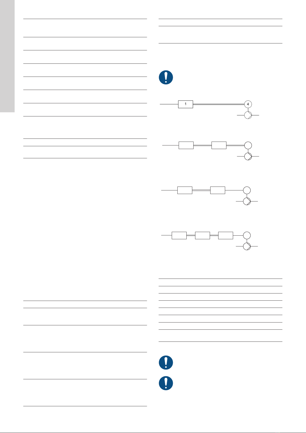
The hazard statements are structured in the following way:
SIGNAL WORD
Description of the hazard
Consequence of ignoring the warning
• Action to avoid the hazard.
1.2 Notes
The symbols and notes below may appear in Grundfos installation
and operating instructions, safety instructions and service
instructions.
Observe these instructions for explosion-proof products.
A blue or grey circle with a white graphical symbol
indicates that an action must be taken.
A red or grey circle with a diagonal bar, possibly with a
black graphical symbol, indicates that an action must not
be taken or must be stopped.
If these instructions are not observed, it may result in
malfunction or damage to the equipment.
Tips and advice that make the work easier.
1.3 References
Technical documentation for Grundfos CUE:
• The manual contains all information required for putting CUE
into operation.
• The data booklet contains all technical information about the
construction and applications of CUE.
• The service instructions contain all required information for
dismantling and repairing the frequency converter.
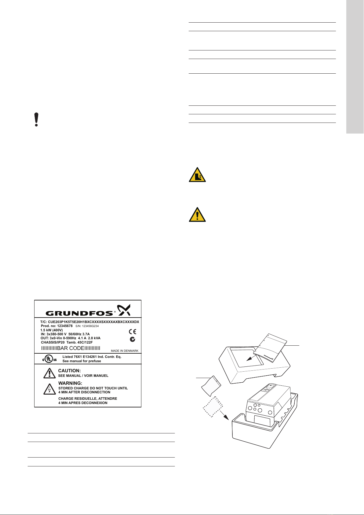
Technical documentation is available in Grundfos Product Center at
www.grundfos.com.
4
English (GB)

If you have any questions, contact the nearest Grundfos company
or service workshop.
2. Product introduction
2.1 Product description
CUE is a series of external frequency converters especially
designed for pumps.
With the startup guide in CUE, the installer can quickly set central
parameters and put CUE into operation.
Connected to a sensor or an external control signal, CUE quickly
adapts the pump speed to the actual demand.
The operating panel displays any alarms or warnings.
If the pump speed exceeds the rated speed, the pump will
be overloaded.
2.2 Intended use
CUE frequency converters can be used in both new and existing
installations. Local operation is performed via the operating panel
which has a graphic display showing the menu structure. The menu
structure uses the same system as Grundfos E-pumps.
Remote operation is performed via external signals, for instance via
digital inputs or GENIbus.
2.3 Applications
The CUE series and Grundfos standard pumps are a supplement to
the Grundfos E-pumps range with an integrated frequency
converter.
A CUE solution offers the same E-pump functionality in these
cases:
• in mains voltage or power ranges not covered by the E-pump
range
• in applications where an integrated frequency converter is not
desirable or permissible.
2.4 Identification
2.4.1 Nameplate
CUE can be identified by means of the nameplate. An example is
shown below.
T/C: CUE203P1K5T5E20H1BXCXXXXSXXXXAXBXCXXXXDX
Prod. no: 12345678
S
/
N
:
123456
G
234
IN: 3x380-500 V 50/60Hz 3.7A
OUT: 3x0-Vin 0-590Hz 4.1 A 2.8 kVA
CHASSIS/IP20 Tamb. 45C/122F
IIIIIIIIIIIBAR CODEIIIIIIIIIII
MADE IN DENMARK
Listed 76X1 E134261 Ind. Contr. Eq.
See manual for prefuse
CAUTION:
SEE MANUAL
/
VOIR MANUEL
WARNING:
STORED CHARGE DO NOT TOUCH UNTIL
4
MIN AFTER DISCONNECTION
CHARGE RESIDUELLE
,
ATTENDRE
4
MIN APRES DECONNEXION
1.5 kW (400V)
TM043272
Example of nameplate
Text Description
T/C: CUE (product name)
202P1M2... (internal code)
Prod. no: Product number: 12345678
S/N: Serial number: 123456G234
Text Description
The last three digits indicate the
production date: 23 is the week,
and 4 is the year 2004.
1.5 kW (2 hp) Typical shaft power of the motor
IN: Supply voltage, frequency and
maximum input current
OUT:
Motor voltage, frequency and
maximum output current. The
maximum output frequency
usually depends on the pump
type.
CHASSIS/IP20 Enclosure class
Tamb. Maximum ambient temperature
2.4.2 Packaging label
CUE can also be identified by means of the label on the packaging.
3. Receiving the product
WARNING
Crushing of feet
Death or serious personal injury
‐Use safety shoes during transport and avoid
stacking boxes.
CAUTION
Lifting hazard
Minor or moderate personal injury
‐Use proper lifting equipment when handling the
product.
‐Follow local regulations.
3.1 Transporting the product
To prevent damage during transport, CUE must only be unpacked
at the installation site.
3.2 Inspecting the product
Check on receipt that the packaging is intact and the unit is
complete. In case of damage, contact the carrier immediately.
Note that CUE is delivered in packaging which is not suitable for
outdoor storage.
3.3 Scope of delivery
The packaging contains one or more accessory
bags, the documentation and the unit itself.
1
2
TM038857
CUE packaging
5
English (GB)

Pos. Description
1 Documentation
2 Accessory bags
3.3.1 Lifting CUE
Always lift the product using the lifting holes. Use a bar to avoid
bending the lifting holes.
TM039896
Recommended lifting method
4. Installation requirements
Any installation, maintenance and inspection must be
carried out by trained persons.
WARNING
Sharp element
Death or serious personal injury
‐Use safety knives and protective gloves when
unpacking the product.
WARNING
Lifting hazard
Death or serious personal injury
‐Use proper lifting equipment when handling the
product.
‐Follow local regulations.
WARNING
Electric shock
Death or serious personal injury
‐Before starting any work on the product, make sure
that the power supply has been switched off at least
for as long as stated below and that it cannot be
accidentally switched on.
‐Touching the electrical parts may be fatal, even after
CUE has been switched off.
Voltage Min. waiting time
4 minutes 15 minutes 20 minutes
200-240 V 0.75 - 3.7 kW
(1 - 5 hp)
5.5 - 45 kW
(7.5 - 60 hp)
380-500 V 0.55 - 7.5 kW
(0.75 - 10 hp)
11 - 90 kW
(15 - 125 hp)
110 - 250 kW
(150 - 350 hp)
525-600 V 0.75 - 7.5 kW
(1 - 10 hp)
11 - 90 kW
(15 - 125 hp)
525-690 V 11 - 250 kW
(15 - 350 hp)
You can only wait for a shorter period of time if stated on the
nameplate of the product in question.
Related information
6. Electrical connection
10. Servicing the product
4.1 Safety regulations
• The OFF button of the operating panel does not disconnect
CUE from the power supply and must therefore not be used as
a safety switch.
• CUE must be earthed correctly and protected against indirect
contact according to local regulations.
• The leakage current to protective earth exceeds 3.5 mA.
• Enclosure class IP20/21 must not be installed freely accessible,
but only in a panel.
• Enclosure class IP54/55 must not be installed outdoors without
additional protection against weather conditions and the sun.
• The STO function does not disconnect CUE from the power
supply and must therefore not be used as a safety switch.
• The STO function does not prevent unwanted movement from
external forces on the motor, for example, back pressure, and
the motor shaft must be covered.
Always observe local regulations concerning cable cross-section,
short-circuit protection and overcurrent protection.
The general safety necessitates special considerations as to these
aspects:
• fuses and switches for overcurrent and short-circuit protection
• selection of cables (mains current, motor, load distribution and
relay)
• net configuration (IT, TN, earthing)
• safety on connecting inputs and outputs (PELV).
4.2 IT mains
Do not connect 380-500 V CUE frequency converters to
mains supplies with a voltage between phase and
protective earth of more than 440 V.
In connection with IT mains and earthed delta mains, the mains
voltage may exceed 440 V between phase and protective earth.
4.3 Aggressive environment
CUE must not be installed in an environment where the air
contains liquids, particles or gases which may affect and
damage the electronic components.
CUE contains a large number of mechanical and electronic
components. They are all vulnerable to environmental impact.
4.4 Reduced performance under certain conditions
CUE reduces its performance under these conditions:
• low air pressure (at high altitude)
• long motor cables.
Related information
4.4.1 Reduction at low air pressure
4.4.2 Reduction in connection with long motor cables
4.4.1 Reduction at low air pressure
At altitudes above 2000 m (6600 ft), the PELV
requirements cannot be met.
PELV = Protective Extra Low Voltage.
At low air pressure, the cooling capacity of air is reduced, and CUE
automatically reduces the performance to prevent overload.
It may be necessary to select a CUE unit with a higher
performance.
Related information
4.4 Reduced performance under certain conditions
4.4.2 Reduction in connection with long motor cables
The maximum cable length is 300 m (1000 ft) for unscreened and
150 m (500 ft) for screened cables. In case of longer cables,
contact Grundfos.
CUE is designed for a motor cable with a maximum cross-section
as stated in sections concerning non-UL fuses and UL fuses.
6
English (GB)

Related information
4.4 Reduced performance under certain conditions
12.3.4 Non-UL fuses and conductor cross-sections to mains and
motor, for installations outside North America
12.3.5 UL fuses and conductor cross-sections to mains and motor,
for installations in North America
5. Mechanical installation
The individual CUE cabinet sizes are characterised by their
enclosures. The table in the technical data section shows the
relationship between the enclosure class and enclosure type.
Related information
12.1 Enclosure
5.1 Enclosure types
Products with integrated STO function must be installed in an IP54
cabinet according to IEC 60529 or in an equivalent environment. In
special applications, a higher IP degree may be necessary.
5.2 Space requirements and air circulation
The CUE units can be mounted side by side, but as sufficient air
circulation is required for cooling, these requirements must be met:
• Sufficient free space above and below the CUE cabinet. See the
table below.
• Ambient temperature up to 50 °C (122 °F).
• The CUE cabinet must be hung directly on the wall or fitted with
a back plate.
TM038859
CUE hung directly on the wall or fitted with a back plate
Required free space above and below the CUE cabinet:
Enclosure Space [mm (in)]
A2, A3, A4, A5 100 (3.9)
B1, B2, B3, B4, C1, C3 200 (7.9)
C2, C4, D1h, D2h, D5h, D7h 225 (8.9)
5.3 Mounting
The user is responsible for mounting CUE securely on a
firm surface.
1. Mark and drill holes.
2. Fit the screws at the bottom, but leave loose. Mount CUE, and
tighten the four screws.
b
aa
b
TM038860
Drilling holes in the wall
Related information
12.5.1 Enclosures A2-A5, B1-B4 and C1-C4
5.4 Mounting on the floor
WARNING
Crushing of feet
Death or serious personal injury
‐CUE is very heavy and may fall over if the pedestal is
not anchored to the floor.
The user is responsible for mounting CUE securely on a
firm surface.
See the pedestal-kit instructions for further information.
By means of a pedestal (optional), CUE can also be mounted on
the floor.
1. Mark the mounting holes on the floor. See the figure below.
2. Drill the holes.
3. Mount the pedestal on the floor.
4. Mount CUE on the pedestal using the enclosed screws.
7
English (GB)

1
2
3
4
5
6
TM059669
Drilling template for pedestal
Pos. D1h
[mm]
D2h
[mm]
D5h/D7h
[mm]
1 400 400 200
2 325 420 326
3 284 379 290
4 240 240 235
5 4 x 14 4 x 14 4 x 14
6 217 317 290
6. Electrical connection
WARNING
Electric shock
Death or serious personal injury
‐Before starting any work on the product, make sure
that the power supply has been switched off and that it
cannot be accidentally switched on. See the section
regarding installation requirements.
‐Touching the electrical parts may be fatal, even after
CUE has been switched off.
The owner or installer is responsible for ensuring correct
earthing and protection according to local regulations.
For products with STO, ensure short-circuit protection of
the cable between terminal 37 and the external safety
device.
Security measures are the responsibility of the user.
The frequency converter parameters can be password
protected.
TM038525
ELCB
Example of three-phase mains connection of CUE with main
switch, backup fuses and additional protection
Related information
4. Installation requirements
6.2 EMC-correct installation
6.5.1 Main switch
9.4 Checking the motor rotation direction
6.1 Electrical protection
6.1.1 Protection against electric shock, indirect contact
CAUTION
Electric shock
Minor or moderate personal injury
‐CUE must be earthed correctly and protected against
indirect contact according to local regulations.
The leakage current to protective earth exceeds 3.5 mA,
and a reinforced earth connection is required.
Protective conductors must always have a yellow and green (PE) or
yellow, green and blue (PEN) colour marking.
Instructions according to EN IEC 61800-5-1:
• CUE must be stationary, installed permanently and connected
permanently to the mains supply.
• The protective earth connection must be carried out with
duplicate protective conductors or with a single reinforced
protective conductor with a cross-section of minimum 10 mm2.
6.1.2 Protection against short circuit, fuses
CUE and the supply system must be protected against short circuit.
Grundfos requires that the backup fuses mentioned in section
"Cable cross-section to signal terminals" are used for protection
against short circuit.
CUE offers complete short-circuit protection in case of a short circuit
on the motor output.
Related information
12.3.3 Cable cross-sections to signal terminals
6.1.3 Additional protection
WARNING
Electric shock
Death or serious personal injury
‐The leakage current to protective earth must exceed
3.5 mA.
If CUE is connected to an electrical installation where an earth
leakage circuit breaker (ELCB/RCD) is used as additional
protection, the circuit breaker must be of a type marked with the
following symbols:
8
English (GB)

TMA06789TM006789
ELCB/RCD
The circuit breaker is type B.
The total leakage current of all the electrical equipment in the
installation must be taken into account.
The leakage current of CUE in normal operation can be seen in the
electrical data section.
During startup and in asymmetrical supply systems, the leakage
current can be higher than normal and may cause the ELCB/RCD
to trip.
Related information
12.4 Electrical data
6.1.4 Motor protection
The motor requires no external motor protection. CUE protects the
motor against thermal overloading and blocking.
6.1.5 Protection against overcurrent
CUE has an internal overcurrent protection for overload protection
on the motor output.
6.1.6 Protection against mains voltage transients
CUE is protected against mains voltage transients according to EN
61800-3, second environment.
6.2 EMC-correct installation
The motor cable must be screened for CUE to meet EMC
requirements.
This section provides guidelines for good practice when installing
CUE. Follow these guidelines to comply with EN 61800-3, first
environment.
• Use only motor and signal cables with a braided metal screen in
applications without output filter.
• There are no special requirements to supply cables, apart from
local requirements.
• Leave the screen as close to the connecting terminals as
possible.
• Avoid terminating the screen by twisting the ends. See the figure
below about not twisting the screen ends. Use cable clamps or
EMC screwed cable entries instead.
• Connect the screen to frame at both ends for both motor and
signal cables. See the figure below with an example
of connection of a 3-conductor bus cable with screen connected
at both ends. If the controller has no cable clamps, connect only
the screen to the CUE cabinet. See the figure below with an
example of connection of a 3-conductor bus cable with screen
connected to CUE (controller with no cable clamps).
• Avoid unscreened motor and signal cables in electrical cabinets
with frequency converters.
• Make the motor cable as short as possible in applications
without output filter to limit the noise level and minimise leakage
currents.
• Screws for frame connections must always be tightened
whether a cable is connected or not.
• Keep mains cables, motor cables and signal cables separated in
the installation if possible.
Other installation methods may give similar EMC results if the
above guidelines for good practice are followed.
TM021325
Example of stripped cable with screen
TM038812
Do not twist the screen ends
1 2
TM038732
Example of connection of a 3-conductor bus cable with screen
connected at both ends
Pos. Description
1 Controller
2 CUE
1 2
TM038731
Example of connection of a 3-conductor bus cable with screen
connected to CUE (controller with no cable clamps)
Pos. Description
1 Controller
2 CUE
Related information
6. Electrical connection
6.3 RFI filters
To meet the EMC requirements, CUE comes with the following
types of built-in radio-frequency interference filters (RFI).
9
English (GB)

Voltage
[V]
Typical shaft power
P2
[kW (hp)]
RFI filter type
1 x 200-240*1.1 - 7.5
(1.5 - 10) C1
3 x 200-240 0.75 - 45
(1 - 60) C1
3 x 380-500 0.55 - 90
(0.75 - 125) C1
3 x 380-500 110 - 250
(150 - 350) C3
3 x 525-600 0.75 - 90
(1 - 125) C3
3 x 525-690 11 - 250
(15 - 350) C3
*Single-phase input - three-phase output.
Description of RFI filter types
C1: For use in domestic areas.
C3: For use in industrial areas with own low-voltage
transformer.
RFI filter types are according to EN 61800-3.
Equipment of category C3
• This type of power drive system (PDS) is not intended to be
used on a low-voltage public network which supplies domestic
premises.
Radio frequency interference is expected if used on such a network.
Related information
12.6.1 Sound pressure level
6.3.1 Output filters
Output filters are used for reducing the voltage stress on the motor
windings and the stress on the motor insulation system as well as
for decreasing acoustic noise from the frequency-converter-driven
motor.
Two types of output filters are available as accessories for CUE:
• dU/dt filters
• sine-wave filters.
Use of output filters
The table below shows when we recommend an output filter and
the type to use. The selection depends on the following:
• pump type
• motor cable length
• the required reduction of the acoustic noise from the motor.
Pump type dU/dt filter Sine-wave filter
SP, BM, BMB with
motor voltage from
380 V and up
-0-300 m*
Pumps with
Grundfos motor
MG71 and MG80 up
to and including 1.5
kW (2 hp)
-0-300 m*
Applications with
desired reduction of
dU/dt and noise
emission, low
reduction
0-150 m*-
Applications with
desired reduction of
dU/dt, voltage peaks
and noise emission,
high reduction
-0-300 m*
Pump type dU/dt filter Sine-wave filter
Applications with
motors of 500 V and
up
-0-300 m*
*The lengths stated apply to the motor cable.
6.4 Motor cable
To meet the requirements of EN 61800-3, the motor cable
must always be a screened cable whether an output filter
is installed or not.
The mains cable does not need to be a screened cable.
See the figures below.
1
4
TM044289
Example of installation without filter
1 2 4
TM044290
Example of installation with filter. The cable between CUE
and filter must be short.
1 2 5
TM044291
Submersible pump without connection box. Frequency converter
and filter installed close to the well.
1 32 5
TM044292
Submersible pump with connection box and screened cable.
Frequency converter and filter installed far away from the
well, and connection box installed close to the well.
Symbol Designation
1 CUE
2 Filter
3 Connection box
4 Standard motor
5 Submersible motor
One line Unscreened cable
Double
line Screened cable
6.5 Mains and motor connection
Check that the mains voltage and frequency correspond
to the values on the nameplate of CUE and the motor.
The motor cable must be screened for CUE to meet EMC
requirements.
The supply voltage and frequency are marked on the CUE
nameplate. Make sure that CUE is suitable for the power supply of
the installation site.
10
English (GB)

Related information
6.8.3.1 Enclosures A2, A3 and B3
6.8.3.2 Enclosures A5, B1, B2, B4, C1, C2, C3, C4, D1 and D2
6.5.1 Main switch
A main switch can be installed before the CUE cabinet according to
local regulations. See the figure in the EMC-correct installation
section.
Related information
6. Electrical connection
6.5.2 Wiring diagram
The wires in the terminal box must be as short as possible.
Excepted from this is the protective conductor which must be so
long that it is the last one to be disconnected in case the wire is
inadvertently pulled out of the cable entry.
TM038799
Wiring diagram, three-phase mains connection
Terminal Function
91 (L1)
Three-phase mains supply92 (L2)
93 (L3)
95/99 (PE) Protective earth connection
96 (U) Three-phase motor connection, 0-100 % of mains
voltage
97 (V)
98 (W)
For single-phase connection, use L1 and L2.
6.5.3 Mains connection, enclosures A2 and A3
Check that the mains voltage and frequency correspond
to the values on the nameplate of CUE and the motor.
Enclosure Torque Nm [ft-lb]
Mains Motor Protective earth Relay
A2 1.8 (1.3) 1.8 (1.3) 3 (2.2) 0.6 (0.4)
A3 1.8 (1.3) 1.8 (1.3) 3 (2.2) 0.6 (0.4)
1. Fit the mounting plate with two screws.
TM039010
Fitting the mounting plate
2. Connect the earth conductor to terminal 95 (PE) and the mains
conductors to terminals 91 (L1), 92 (L2) and 93 (L3) of the
mains plug.
TM039011
Connecting the earth conductor and mains conductors
For single-phase connection, use L1 and L2.
3. Fix the mains cable to the mounting plate.
TM039014
Fixing the mains cable
11
English (GB)

6.5.4 Motor connection, enclosures A2 and A3
1. Connect the earth conductor to terminal 99 (PE) on the
mounting plate.
2. Connect the motor conductors to terminals 96 (U), 97 (V) and 98
(W) of the motor plug.
TM074879
Connecting the earth conductor and motor conductors
1. Insert the motor plug into the socket marked "MOTOR".
2. Fix the screened cable to the mounting plate with a cable clamp.
Related information
6.8.3.1 Enclosures A2, A3 and B3
6.5.5 Mains connection, enclosures A4 and A5
Enclosure Torque Nm [ft-lb]
Mains Motor Protective earth Relay
A4 1.8 (1.3) 1.8 (1.3) 3 (2.2) 0.6 (0.4)
A5 1.8 (1.3) 1.8 (1.3) 3 (2.2) 0.6 (0.4)
1. Connect the earth conductor to terminal 95 (PE). See the figure
below.
2. Connect the mains conductors to terminals 91 (L1), 92
(L2) and 93 (L3) of the mains plug.
3. Insert the mains plug into the socket marked "MAINS".
4. Fix the mains cable with a cable clamp.
TM039017
Mains connection, A4 and A5
For single-phase connection, use L1 and L2.
6.5.6 Motor connection, enclosures A4 and A5
1. Connect the earth conductor to terminal 99 (PE). See the figure
below.
2. Connect the motor conductors to terminals 96 (U), 97 (V) and 98
(W) of the motor plug.
3. Insert the motor plug into the socket marked "MOTOR".
4. Fix the screened cable with a cable clamp.
TM039018
Motor connection, A4 and A5
6.5.7 Mains connection, enclosures B1 and B2
Enclosure Torque Nm [ft-lb]
Mains Motor Protective earth Relay
B1 1.8 (1.3) 1.8 (1.3) 3 (2.2) 0.6 (0.4)
B2 4.5 (3.3) 4.5 (3.3) 3 (2.2) 0.6 (0.4)
1. Connect the earth conductor to terminal 95 (PE). See the figure
below.
2. Connect the mains conductors to terminals 91 (L1), 92
(L2) and 93 (L3).
3. Fix the mains cable with a cable clamp.
TM039019
Mains connection, B1 and B2
12
English (GB)

For single-phase connection, use L1 and L2.
6.5.8 Motor connection, enclosures B1 and B2
1. Connect the earth conductor to terminal 99 (PE). See the figure
below.
2. Connect the motor conductors to terminals 96 (U), 97 (V) and 98
(W).
3. Fix the screened cable with a cable clamp.
TM039020
Motor connection, B1 and B2
6.5.9 Mains connection, enclosures B3 and B4
Enclosure Torque Nm [ft-lb]
Mains Motor Protective earth Relay
B3 1.8 (1.3) 1.8 (1.3) 3 (2.2) 0.6 (0.4)
B4 4.5 (3.3) 4.5 (3.3) 3 (2.2) 0.6 (0.4)
1. Connect the earth conductor to terminal 95 (PE). See the figures
in the motor connection section for enclosures B3 and B4.
2. Connect the mains conductors to terminals 91 (L1), 92
(L2) and 93 (L3).
3. Fix the mains cable with a cable clamp.
Related information
6.5.10 Motor connection, enclosures B3 and B4
1. Connect the earth conductor to terminal 99 (PE). See the figures
below.
2. Connect the motor conductors to terminals 96 (U), 97 (V) and 98
(W).
3. Fix the screened cable with a cable clamp.
1
2
TM039446
Mains and motor connection, B3
Pos. Description
1 Mains
2 Motor
TM039449
Mains and motor connection, B4
Related information
6.5.9 Mains connection, enclosures B3 and B4
6.5.11 Mains connection, enclosures C1 and C2
Enclosure
Torque Nm [ft-lb]
Mains Motor Protective
earth Relay
C1 10 (7.4) 10 (7.4) 3 (2.2) 0.6 (0.4)
C2 141/242
(10.31/17.72)
141/242
(10.31/17.72)3 (2.2) 0.6 (0.4)
1Conductor cross-section ≤ 95 mm2 (≤ 4/0 AWG)
2Conductor cross-section ≥ 95 mm2 (≥ 4/0 AWG).
1. Connect the earth conductor to terminal 95 (PE). See the
section for mains and motor connections for enclosures C1 and
C2.
2. Connect the mains conductors to terminals 91 (L1), 92
(L2) and 93 (L3).
Related information
6.5.12 Motor connection, enclosures C1 and C2
13
English (GB)

6.5.12 Motor connection, enclosures C1 and C2
1. Connect the earth conductor to terminal 99 (PE). See the figure
below.
2. Connect the motor conductors to terminals 96 (U), 97 (V) and 98
(W).
3. Fix the screened cable with a cable clamp.
TM039016
Mains and motor connection, C1 and C2
Related information
6.5.11 Mains connection, enclosures C1 and C2
6.5.13 Mains connection, enclosures C3 and C4
Enclosure
Torque Nm [ft-lb]
Mains Motor Protective
earth Relay
C3 10 10 3 (2.2) 0.6 (0.4)
C4 141/242
(10.31/17.72)
141/242
(10.31/17.72)3 (2.2) 0.6 (0.4)
1Conductor cross-section ≤ 95 mm2 (≤ 4/0 AWG)
2Conductor cross-section ≥ 95 mm2 (≥ 4/0 AWG).
1. Connect the earth conductor to terminal 95 (PE). See the
section for mains and motor connections for enclosures C3 and
C4.
2. Connect the mains conductors to terminals 91 (L1), 92
(L2) and 93 (L3).
3. Fix the mains cable with a cable clamp.
Related information
6.5.14 Motor connection, enclosures C3 and C4
1. Connect the earth conductor to terminal 99 (PE). See the figure
below.
2. Connect the motor conductors to terminals 96 (U), 97 (V) and 98
(W).
3. Fix the screened cable with a cable clamp.
TM039448
Mains and motor connection, C3
TM039447
Mains and motor connection, C4
Related information
6.5.13 Mains connection, enclosures C3 and C4
6.5.15 Gland plate, enclosures D1h, D2h, D5h and D7h
Cables are connected through the gland plate from the bottom. The
gland plate must be fitted to CUE to ensure the specified protection
degree as well as to ensure sufficient cooling.
Drill holes in the marked areas. See the figures below.
14
English (GB)

TM059326
CUE viewed from the bottom [mm]
224
[8.8]
111
[4.4]
242
121
43
[1.7] [4.8]
[9.5]
12
TM077429
Gland plate, enclosure D5h
222
[8.7]
115
[4.5]
1
2
43
[1.7]
169
[6.6]
337
[13.3]
TM077430
Gland plate, enclosure D7h
6.5.16 Mains connection, enclosures D1h and D2h
Enclosure Torque Nm [ft-lb]
Mains Motor Protective earth Relay
D1h 19-40 19-40 3 (2.2) 0.6 (0.4)
D2h 19-40 19-40 3 (2.2) 0.6 (0.4)
1. Connect the earth conductor to terminal 95 (PE).
2. Connect the mains conductors to terminals 91 (L1), 92
(L2) and 93 (L3).
3. Fix the mains cable with a cable clamp.
6.5.17 Motor connection, enclosures D1h, D2h, D5h and D7h
Take the following terminal positions into consideration when you
design the cable connection.
1. Connect the earth conductor to terminal 99 (PE). See the figures
below.
2. Connect the motor conductors to terminals 96 (U), 97 (V) and 98
(W).
3. Fix the screened cable with a cable clamp.
TM059329
Earth, mains and motor connection for D1h and D2h
15
English (GB)

TM077427
Earth, mains and motor connection for D5h
TM077428
Earth, mains and motor connection for D7h
6.6 STO installation, optional
DANGER
Exposure to high pressure or toxic liquids
Death or serious personal injury
‐Failure to remove the jumper disables the STO
function, and the motor might not stop as
intended, and can cause severe injury or death.
‐Failure to use safety-monitoring relay compliant with
Category 3/PL d according to ISO 13849-1 or SIL
2 according to EN 62061 and IEC 61508 can cause
death or serious personal injury. Perform a functional
test every 12 months to ensure that the system works
properly.
To enable the integrated STO, follow these steps:
1. Remove the jumper wire between control terminals 37 and 12 or
13. Cutting or breaking the jumper is not sufficient to avoid
short-circuiting.
12/13
37
TM074595
1. Connect an external safety-monitoring relay via a NO safety
function to terminal 37 (STO) and either terminal 12 or 13, 24 V
DC.
Select and apply the components in the safety control system
appropriately to achieve the desired level of operational safety.
Before integrating and using STO in an installation, carry out a
thorough risk analysis on the installation to determine whether the
STO functionality and safety levels are appropriate and sufficient.
12
37
1
3
FC
4
2
TM074594
STO wiring
Pos. Description
1 Reset button
2 Safety relay (category 3, PL d or SIL2)
3 Emergency stop button
4Short-circuit protected cable if the product is not
installed inside an IP54 cabinet.
6.6.1 Restart behaviour after STO activation
By default, the STO function is set to unintended-restart prevention
behaviour. To terminate STO and resume normal operation
with a manual reset, do the following:
• Reapply 24 V DC supply to terminal 37.
• Send a reset signal via bus, Digital I/O or the reset button.
• Set the STO function to automatic restart by changing the value
of 5-19 terminal 37 Safe Stop from default value 1, Safe Stop
Alarm to value 3, Safe Stop Warning.
Automatic restart means that STO is terminated and normal
operation is resumed, as soon as the 24 V DC is applied to terminal
37. No reset signal is required.
Related information
6.7 Connecting the signal terminals
16
English (GB)

6.6.2 Restart settings
• Remove the 24 V DC voltage supply to terminal 37 using the
interrupt device while the frequency converter drives the motor,
that is the mains supply is not interrupted.
• Check that the motor coasts and that the alarm Safe Stop
displays in the local operating panel, if mounted.
• Reapply 24 V DC to terminal 37.
• Make sure that the motor remains in the coasted state.
• Send a reset signal via bus, Digital I/O or the reset button.
• Make sure that the motor becomes operational again.
6.7 Connecting the signal terminals
As a precaution, signal cables must be separated from
other cable groups by reinforced insulation in their entire
lengths.
Connect the signal cables according to the guidelines for good
practice to ensure EMC-correct installation.
• Use screened signal cables with a cable cross-section of
minimum 0.5 mm2 and maximum 1.5 mm2.
• Use a 3-conductor screened bus cable in new systems.
Related information
6.6.1 Restart behaviour after STO activation
6.7.1 Wiring diagram, signal terminals
U: 0-10 V
I: 0/4-20 mA
TM051506
External setpoint, voltage input
TM051508
2-wire sensor
TM051507
External setpoint, current input
17
English (GB)

39 42 50 53 54 55
61 68 69
61 68 69
12 13 18 19 27 29 32 33 20 37
A53
UIUI
A54
TM075269
3-wire sensor
Terminal Type Function
12 +24 V out Supply to sensor
13 +24 V out Additional supply
18 DI 1 Digital input, programmable
19 DI 2 Digital input, programmable
20 GND Common frame for digital inputs
27 DI/O 1 Digital input/output,
programmable
29 DI/O 2 Digital input/output,
programmable
32 DI 3 Digital input, programmable
33 DI 4 Digital input, programmable
37 Safe stop Safe stop
39 GND Frame for analog output
42 AO 1 Analog output, 0-20 mA
50 +10 V out Supply to potentiometer
53 AI 1 External setpoint, 0-10 V, 0/4-20
mA
54 AI 2 Sensor input, sensor 1, 0/4-20
mA
55 GND Common frame for analog
inputs
61 RS-485 GND Y GENIbus, frame
68 RS-485 A GENIbus, signal A (+)
69 RS-485 B GENIbus, signal B (-)
The RS-485 screen must be connected to the frame.
6.7.2 Connection of a thermistor (PTC) to CUE
A PELV circuit provides protection against electric shock. Special
connection requirements apply to this type of circuit. The
requirements are described in EN 61800-5-1.
In order to maintain PELV, all connections made to the control
terminals must be PELV. For example, the thermistor must have
reinforced or double insulation.
6.7.2.1 Accessing the signal terminals
All signal terminals are behind the terminal cover on the front side
of CUE. Remove the terminal cover as shown in the figures below.
TM039003
Access to signal terminals, A2 and A3
TM039004
Access to signal terminals, A4, A5, B1, B2, B3, B4, C1, C2, C3
and C4
18
English (GB)

TM059654
Access to signal terminals, D1h and D2h
1
2
3
TM039025
Signal terminals, all enclosures
6.7.2.2 Fitting the conductor
1. Remove the insulation at a length of 9 to 10 mm.
2. Insert a screwdriver with a tip of maximum 0.4 × 2.5 mm into the
square hole.
3. Insert the conductor into the corresponding round hole. Remove
the screwdriver. The conductor is now fixed in the terminal.
TM039026
Fitting the conductor into the signal terminal
6.7.2.3 Setting the analog inputs, terminals 53 and 54
Contacts A53 and A54 are positioned behind the operating panel
and used for setting the signal type of the two analog inputs.
The factory setting of the inputs is voltage signal "U".
If a 0/4-20 mA sensor is connected to terminal 54, the
input must be set to current signal "I".
Switch off the power supply before setting contact A54.
Remove the operating panel to set the contact. See the figure
below.
U I
A53
U I
A54
TM039104
Setting contact A54 to current signal "I"
6.7.2.4 RS-485 GENIbus network connection
One or more CUE units can be connected to a control unit via
GENIbus.
The reference potential, GND, for RS-485 (Y) communication must
be connected to terminal 61.
If more than one CUE unit is connected to a GENIbus network, the
termination contact of the last CUE must be set to ON (termination
of the RS-485 port).
The factory setting of the termination contact is OFF (not
terminated).
Remove the operating panel to set the contact. See the figure
below.
19
English (GB)

OFF ON
BUS TER
TM039006
Setting the termination contact to ON
6.8 Connecting the signal relays
As a precaution, signal cables must be separated from
other cable groups by reinforced insulation in their entire
lengths.
TM038801
Terminals for signal relays in normal state (not activated)
Terminal Function
C 1 C 2 Common
NO 1 NO 2 Normally open contact
NC 1 NC 2 Normally closed contact
6.8.1 Access to signal relays
The relay outputs are positioned as shown in the figures below.
TM039007
Terminals for relay connection, A2 and A3
TM039008
Terminals for relay connection, A4, A5, B1 and B2
TM039009
Terminals for relay connection, C1 and C2
20
English (GB)
Other manuals for CUE
12
Table of contents
Other Grundfos DC Drive manuals

Grundfos
Grundfos Redi-Flo Series User manual

Grundfos
Grundfos CUE Series User manual

Grundfos
Grundfos CUE Operating manual

Grundfos
Grundfos CUE Series User manual

Grundfos
Grundfos MGE 71 Series User manual

Grundfos
Grundfos DMX Series User manual

Grundfos
Grundfos CU331SP User manual

Grundfos
Grundfos CUE Operating manual

Grundfos
Grundfos CUE Series Operating instructions