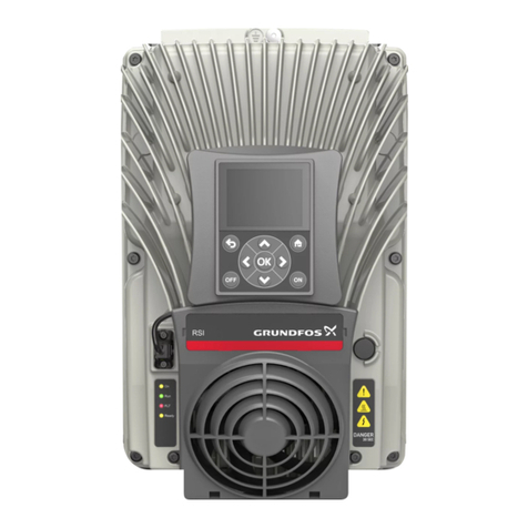
Grundfos RSI User manual

RSI, 1.5-250 kW (2-340 hp)
SOLAR APPLICATION
Installation and operating instructions
GRUNDFOS INSTRUCTIONS


English (GB) Installation and operating instructions
Original installation and operating instructions
Table of contents
1. Grundfos RSI................. 5
1.1 Specific functions of Grundfos RSI ...... 5
2. Safety ..................... 6
2.1 Danger .................... 6
2.2 Warnings ................... 6
3. Receiving the product............ 7
3.1 Lifting the product ............... 7
4. Installation ..................10
4.1 Danger ....................10
4.2 Warning ....................10
4.3 Ventilation ...................11
4.4 Electrical protection ..............11
4.5 DC fuse selection ...............12
4.6 Manufacturers of gPV fuses .........13
4.7 Parallel diode selection ............14
4.8 Photovoltaic system dimensioning ......16
4.9 Power ratings .................18
4.10 Grounding ...................20
4.11 AC grid connection ..............20
4.12 External +24 V supply ............21
4.13 DC power connection .............21
5. Startup ....................25
5.1 Operating panel ................25
5.2 Startup wizard parameter description ....26
5.3 Description of the applications ........27
6. User interfaces................38
6.1 Keypad of the drive ..............38
6.2 Grundfos PC tool ...............46
6.3 Example of control connections .......61
7. Monitoring menu ..............63
7.1 Monitor group .................63
8. Parameters ..................72
8.1 Application parameter lists ..........72
8.2 Additional parameter information..... 127
9. Faults ................... 167
9.1 Fault tracing ................ 167
9.2 Fault appears ............... 167
9.3 Fault history ................ 168
9.4 Fault codes and remedies ........ 168
10. Document quality feedback ...... 179
4
English (GB)

1. Grundfos RSI
The Grundfos RSI contains a preloaded Grundfos
motor library for instant use.
1.1 Specific functions of Grundfos RSI
The dedicated application software was developed to
drive a Solar Pump with an optimized MPPT
(Maximum Power Point Tracking) for RSI supplied by
Solar Panels.
The MPPT is based on 4 parallel algorithms:
• Feed-Forward Controller (to follow the radiation
variations)
• Correction Controller (to compensate the
temperature variations)
• Oscillation Damping Regulator (to prevent the
panel entering in the "current source" branch of
the characteristic)
• Local Maxima logic (to prevent the regulator from
being trapped in a local maximum lower than
absolute maximum)
Features
• The MPP Tracker controls DC voltage reference
in order to find the maximum power.
• Extensive wizards for start-up, PID-control used to
facilitate commissioning
• "Funct" button for easy change between Local
(keypad) and Remote control place. The remote
control place is selectable by parameter (I/O or
Fieldbus)
• 8 preset frequencies
• Motor potentiometer functions
• 2 programmable ramp times, 2 supervisions and 3
ranges of prohibited frequencies
• Control page for easy operation and monitoring of
the most essential values.
• Fieldbus data mapping
• Automatic reset
• Different pre-heat modes used to avoid
condensation problems
• Maximum output frequency 320 Hz
• Real-time clock and timer functions available
(optional battery required). Possible to program 3
time channels to achieve different functions on the
drive (e.g. Start/Stop and Preset frequencies)
• External PID-controller available. Can be used to
control e.g. a valve using the AC drive I/O
• Sleep mode function which automatically enables
and disables drive running with user defined
levels to save energy.
• 2-zone PID-controller (2 different feedback
signals; minimum and maximum control)
• Two setpoint sources for the PID-control.
Selectable with digital input
• PID setpoint boost function
• Feedforward function to improve the response to
the process changes
• Process value supervision
• Maintenance counter
• Underload protection can be managed by
measuring Motor torque (standard sensorless
mode) or by measuring the water flow with a flow
meter sensor. This sensor can be an analogue
signal or a digital input. With this sensor it is
possible to measure the water flow [litres/min] and
the total volume of the water flow [m3].
• Sleep mode can be enabled or disabled with a
parameter.
• Digital inputs can be used to measure water levels
(minimum and maximum).
5
English (GB)

2. Safety
This manual contains clearly marked warning
information which is intended for your personal safety
and to avoid any unintentional damage to the product
or connected appliances.
Before installing, commissioning or using the
frequency converter, please read the warning
information contained in RSI Installation Manual.
Please read the following additional safety
instructions carefully.
Only authorized, trained and qualified personnel are
allowed to install, operate and maintain the drive.
2.1 Danger
These warnings are intended to personnel
responsible for grounding the frequency converter.
Ignoring the following instructions can be extremely
dangerous and may cause death or severe injury.
DANGER
Electric shock
Death or serious personal injury
‐Ground the frequency converter to
ensure personnel safety and to reduce
electromagnetic interference.
DANGER
Electric shock
Death or serious personal injury
‐After disconnecting the AC drive from
the mains or from the DC input supply,
wait until the indicators on the keypad
go out (if no keypad is attached, see
the indicators on the cover). Wait an
additional 60 seconds before starting
any work on the connections of RSI.
After expiration of this time, use
measuring equipment to absolutely
ensure that no voltage is present.
Always ensure absence of voltage
before starting any electrical work!
2.2 Warnings
WARNING
Electric shock
Death or serious personal injury
‐The touch current of RSI exceeds 3.5
mA AC. According to standard
EN61800-5-1, a reinforced protective
ground connection must be ensured.
See RSI Installation Manual for further
information.
WARNING
Electric shock
Death or serious personal injury
‐Never work on the photovoltaic
generator or frequency converter and
its input/output cables when the
frequency converter is connected to
the mains or to the photovoltaic
generator.
WARNING
Electric shock
Death or serious personal injury
‐Before performing any measurement
on the frequency converter, disconnect
or isolate the mains supply voltage or
the DC input supply.
WARNING
Electric shock
Death or serious personal injury
‐Do not touch the components on the
frequency converter or on the string
box cabinet that have high DC voltage.
WARNING
Electric shock
Death or serious personal injury
‐The photovoltaic generator cells
exposed to light supply DC voltage
even at low light intensity.
6
English (GB)
3. Receiving the product
3.1 Lifting the product
WARNING
Lifting heavy load
Death or serious personal injury
‐Do not walk under suspended loads.
‐Use lifting devices that are appropriate
for the weight of the unit.
‐Use the recommended lifting method.
1. The AC drive is delivered horizontally in a
cardboard box or on a wooden pallet. Open the
package only when you install the drive.
2. Do not keep the drive in storage in the vertical
position.
3.1.1 Weight of the AC drive
The weights of AC drives of different enclosure sizes
are different. It can be necessary for you to use a
lifting device to move the drive from its package. See
the weights of the different enclosure sizes in below
table.
Weights of RSI drives (A-C)
Enclosure size Weight
[kg] [lb]
A 8.8 19.4
B 14.9 32.8
C 31.5 69.4
Weights of RSI wall-mounted drives (MR4-MR9)
Enclosure size Weight
[kg] [lb]
MR4 6.0 13.2
MR5 10.0 20.0
MR6 20.0 44.1
MR7 37.5 82.7
MR8 66.0 145.5
MR9 119.5 263.5
7
English (GB)

Weights of RSI drive modules (MR8-MR10)
Enclosure size or item Weight
[kg] [lb]
MR8 IP00 drive module 50 110
MR9 IP00 drive module 107 214
MR10 IP00 drive module 221 487
MR10 IP00 drive module and the options module with the brake chopper 252 556
MR10 IP00 drive module and the options module with the brake chopper and
the common-mode filter 258 569
MR10 IP00 drive module and the options module with the brake chopper, the
common- mode filter, and the dU/dt filter 289 637
MR10 IP00 drive module and the options module with AC fuses and fuse
switch (+CIFD) 332 732
3.1.2 Lifting enclosure sizes A-C and MR4-MR9
≤45° ≤45°
≤45°
TM083241
Lifting enclosure sizes A-C and MR4-MR9
8
English (GB)

1. Remove the drive from the cardboard box or the pallet where it was bolted to.
2. Use a lifting device that is sufficiently strong for the weight of the drive.
3. Put the lifting hooks symmetrically in a minimum of 2 holes.
4. The maximum lifting angle is 45°.
3.1.3 Lifting RSI drive module MR10 without options
AA
TM083242
Lifting RSI drive module MR10 without options
1. Remove the drive from the package.
2. Make sure that the support (A in fig. Lifting RSI drive module MR10 without options) is attached to the bottom
of the drive. It gives the terminals protection when you lift the drive or put it vertically on the floor.
3. Use a lifting device that is sufficiently strong for the weight of the drive.
4. Put the lifting hooks in the holes on the top of the cabinet. The maximum lifting angle is 60°.
5. After the lifting, you can remove the support if necessary. You can also use it as a fixing bracket.
9
English (GB)

3.1.4 Lifting RSI drive module MR10 with an options module
≤60°
TM083243
Lifting RSI drive module MR10 with an options module
1. Remove the drive from the package.
2. Use a lifting device that is sufficiently strong for the weight of the drive.
3. Put the lifting hooks in the holes on the top of the cabinet. The maximum lifting angle is 60°.
4. Lift the drive into a vertical position.
4. Installation
The installation instructions in this chapter are
intended only for RSI (A-C) and RSI (MR5-MR10)
drives with additional solar pump application. See the
corresponding operating guide/installation manual for
more installation instructions.
4.1 Danger
DANGER
Electric shock
Death or serious personal injury
‐The terminals are live when the drive is
connected to a photovoltaic system.
Photovoltaic cells generate DC voltage
even at low intensity of sunlight.
DANGER
Electric shock
Death or serious personal injury
‐Wait 60 seconds until the drive is
discharged, before switching between
AC and DC supply (photovoltaic
system) and vice versa.
4.2 Warning
WARNING
Electric shock
Death or serious personal injury
‐Do not remove the EMC screws in the
solar pump application. IT (impedance-
grounded) AC supply network is not
allowed in the solar pump application.
10
English (GB)

4.3 Ventilation
The following requirements must be met to
ensure sufficient air circulation:
• Sufficient free space above and below the RSI
drive. See the table below.
• Ambient temperature up to 60 °C (140 °F).
• The RSI drive must be hung directly on the wall or
fitted with a back plate.
Required free space above and below the RSI drive:
A
CB
A
T
TM085605
Enclosure Space [mm (in)]
A B C
RSI (A-C)
RSI (MR5-MR10) 80 (3.15) 160 (6.3) 60 (2.36)
A = Clearance left and right from the drive
B = Clearance above the drive
C = Clearance underneath the AC drive drive
4.4 Electrical protection
WARNING
Electric shock
Death or serious personal injury
‐The leakage current to protective earth
must exceed 3.5 mA.
If RSI is connected to an electrical installation where
an earth leakage circuit breaker (ELCB/RCD) is used
as additional protection, the circuit breaker must be of
a type marked with the following symbols:
ELCB/RCD
The circuit breaker is type B.
The total leakage current of all the electrical
equipment in the installation must be taken into
account.
During startup and in asymmetrical supply systems,
the leakage current can be higher than normal and
may cause the ELCB/RCD to trip.
11
English (GB)

4.5 DC fuse selection
The fuses on the DC-Input of the inverter must have
the following characteristics:
Fuse characteristics
Fuse type Min. voltage rating
DC current 1000 V
It is recommended to use gPV fuses, which are
developed for solar application, in order to protect
cables and panels against reverse over current, when
multiple strings are connected in parallel. See chapter
4.6 Manufacturers of gPV fuses for recommended
gPV fuse manufacturer.
The photovoltaic fuses have to meet the IEC 60269-6
or the UL 2579 standard.
The maximum ISC PV and inverter back-feed current
depend on the used DC fuses. Make sure that the
breaking capacity of the fuses is sufficient for the final
application. Also, local regulations must be taken into
account.
See the tables below for recommended fuse sizes.
Recommended fuse sizes, Mains voltage 3AC 208-240 V, 50/60 Hz, up to 400 V in V DC
Enclosure size AC drive type
Rated
continuous
current
[A]
IEC60269-6
Fuse size
[A]
UL-2579 Fuse
size
[A]
Total number of
fuses
A
0007 6.6 12 12 2
0008 8.0 15 15 2
0011 11.0 20 20 2
0012 12.5 20 25 2
B
0018 18.0 30 40 2
0024 24.0 40 50 2
0031 31.0 50 63 2
C0048 48.0 80 100 2
0062 62.0 100 125 2
MR5
0018 18.0 30 40 2
0024 24.0 40 50 2
0031 31.0 50 63 2
MR6 0048 48.0 80 100 2
0062 62.0 100 125 2
MR7
0075 75.0 125 160 2
0088 88.0 160 200 2
0105 105.0 200 200 2
MR8
0140 140.0 250 315 2
0170 170.0 315 400 2
0205 205.0 400 400 2
MR9A 0261 261.0 500 500 2
0310 310.0 600 630 2
12
English (GB)

Recommended fuse sizes, Mains voltage 3AC 380-480/500 V, 50/60 Hz, up to 800 V in V DC
Enclosure size AC drive type
Rated
continuous
current
[A]
IEC60269-6
Fuse size
[A]
UL-2579 Fuse
size
[A]
Total number of
fuses
A
0003 3.4 6 6 2
0004 4.8 8 8 2
0005 5.6 10 10 2
0008 8.0 12 15 2
0009 9.6 15 16 2
0012 12.0 20 20 2
B
0016 16.0 25 30 2
0023 23.0 40 40 2
0031 31.0 50 63 2
C
0038 38.0 63 63 2
0046 46.0 80 80 2
0061 61.0 100 100 2
0072 72.0 125 125 2
MR5
0016 16.0 30 30 2
0023 23.0 40 50 2
0031 31.0 50 63 2
MR6
0038 38.0 63 80 2
0046 46.0 80 100 2
0061 61.0 100 125 2
MR7
0072 72.0 125 150 2
0087 87.0 160 200 2
0105 105.0 200 200 2
MR8
0140 140.0 250 315 2
0170 170.0 315 400 2
0205 205.0 400 400 2
MR9A 0261 261.0 500 500 2
0310 310.0 600 630 2
MR9B 0386 385.0 2 x 350 2 x 400 4
MR10 0385 385.0 2 x 350 2 x 400 4
0460 460.0 2 x 500 2 x 500 4
4.6 Manufacturers of gPV fuses
Recommended manufacturers of gPV type fuses:
• Littelfuse
• Siba
• Bussmann
• Mersen
• ETI
• DF Electric
13
English (GB)

4.7 Parallel diode selection
When RSI A-C or RSI MR5-MR10 is used in the Solar
Pump application, a diode must be connected
between DC+ and DC- to protect the inverter against
reverse voltage. See tables below for diode
specification.
Diode specification, Mains voltage 3AC 208-240 V, 50/60 Hz, up to 400 V in V DC
AC drive Diode
specifications
Enclosure size AC drive type Min. IFav
[A]
Min. Voltage rating
[V]
Max. Vf [V]
@ IFav [A]
A
0007 15
1200 1.5
0008 18
0011 25
0012 28
B
0018 40
0024 54
0031 70
C0048 110
0062 140
MR5
0018 50
1200 1.5
0024 63
0031 80
MR6 0048 125
0062 160
MR7
0075 200
0088 250
0105 250
MR8
0140 400
0170 500
0205 500
MR9A 0261 625
0310 800
14
English (GB)

Diode specification, Mains voltage 3AC 380-480/500 V, 50/60 Hz, up to 800 V in V DC
AC drive Diode specifications
Enclosure size AC drive type Min. IFav
[A]
Min. Voltage rating
[V]
Max. Vf [V]
@ IFav [A]
A
0003 8
1200 1.5
0004 12
0005 12
0008 18
0009 22
0012 28
B
0016 36
0023 50
0031 70
C
0038 85
0046 100
0061 140
0072 160
MR5
0016 40
1200 1.5
0023 63
0031 80
MR6
0038 100
0046 140
0061 160
MR7
0072 200
0087 250
0105 250
MR8
0140 400
0170 500
0205 500
MR9A 0261 625
0310 800
MR9B 0386 1000
MR10 0385 1000
0460 1250
15
English (GB)

4.8 Photovoltaic system dimensioning
The photovoltaic system has to be dimensioned in
order to not exceed the values specified in the tables
below. The RSI enclosure sizes are A-C and MR5-
MR10.
Non-isolated inverters must be used with PV modules
that have an IEC 61730 Class A rating.
AC drive (208-240 V 3AC 50/60 Hz, up to 400 V DC) DC-link input ratings
Enclosure
size AC drive type DC supply
[V DC]
Max.
recommende
d PV array
power
[kW]
Vmax PVa
(absolute
maximum)
[V DC]
PV input
operating
voltage
range
[V DC]
Maximum
operating PV
input current
[A DC]
A
0006
234-400
No tolerance
permissible,
0%
2.2 400 234-400 7.0
0008 3.0 400 234-400 9.0
0011 4.4 400 234-400 12.0
0012 6.0 400 234-400 14.0
B
0018 8.0 400 234-400 20.0
0024 11.0 400 234-400 27.0
0031 15.0 400 234-400 35.0
C0048 22.0 400 234-400 54.0
0062 30.0 400 234-400 69.0
MR5
0018
234-400
No tolerance
permissible,
0%
8.0 400 234-400 20.0
0024 11.0 400 234-400 27.0
0031 15.0 400 234-400 35.0
MR6 0048 22.0 400 234-400 54.0
0062 30.0 400 234-400 71.0
MR7
0075 37.0 400 234-400 85.0
0088 44.0 400 234-400 101.0
0105 60.0 400 234-400 121.0
MR8
0140 74.0 400 234-400 161.0
0170 90.0 400 234-400 198.0
0205 110.0 400 234-400 239.0
MR9A 0261 150.0 400 234-400 304.0
0310 180.0 400 234-400 361.0
16
English (GB)

AC drive (380-480/500 V 3AC 50/60Hz, up to 800 V DC) DC-link input ratings
Enclosure
size AC drive type DC supply
[V DC]
Max.
recommende
d PV array
power
[kW]
Vmax PVa
(absolute
maximum)
[V DC]
PV input
operating
voltage
range
[V DC]
Maximum
operating PV
input current
[A DC]
A
0003
300/436-800
No tolerance
permissible,
0%
2.2 800 300/436-800 4.0
0004 3.0 800 300/436-800 5.0
0005 4.4 800 300/436-800 6.0
0008 6.0 800 300/436-800 9.0
0009 8.0 800 300/436-800 11.0
0012 11.0 800 300/436-800 13.0
B
0016 15.0 800 300/436-800 18.0
0023 22.0 800 300/436-800 26.0
0031 30.0 800 300/436-800 34.0
C
0038 37.0 800 300/436-800 42.0
0046 44.0 800 300/436-800 51.0
0061 60.0 800 300/436-800 68.0
0072 74.0 800 300/436-800 80.0
MR5
0016
436-800
No tolerance
permissible,
0%
15.0 800 436-800 18.0
0023 22.0 800 436-800 26.0
0031 30.0 800 436-800 35.0
MR6
0038 37.0 800 436-800 43.0
0046 44.0 800 436-800 52.0
0061 60.0 800 436-800 69.0
MR7
0072 74.0 800 436-800 82.0
0087 90.0 800 436-800 100.0
0105 110.0 800 436-800 121.0
MR8
0140 150.0 800 436-800 161.0
0170 180.0 800 436-800 198.0
0205 220.0 800 436-800 239.0
MR9A 0261 264.0 800 436-800 304.0
0310 320.0 800 436-800 361.0
MR9B 0386 400.0 800 436-800 454.0
MR10 0460 500.0 800 436-800 542.0
17
English (GB)

4.9 Power ratings
AC drive (208-240 V 3AC 50/60 Hz, up to 400 V DC) output ratings
Enclosure
size
AC drive
type
Voltage
(nominal
or range)
[V AC]
Current
(maximu
m
continuou
s)
[A AC]
Current
(inrush)
[A AC]
(2 s)
Frequenc
y
(nominal
or range)
[Hz]
Power
(maximu
m
continuou
s)
[W]
(230 V)
Power
factor
range
Max.
output
fault
current
[A AC]
Max.
output
over
current
protection
[A AC]
A
0006 0-240 6.6 13.2 0-320 1100 0.3-1 19.9 19.9
0008 0-240 8.0 16.0 0-320 1500 0.3-1 26.3 26.3
0011 0-240 11.0 22.0 0-320 2200 0.3-1 33.1 33.1
0012 0-240 12.5 25.0 0-320 3000 0.3-1 39.8 39.8
B
0018 0-240 18.0 36.0 0-320 4000 0.3-1 72.3 72.3
0024 0-240 24.2 48.4 0-320 5500 0.3-1 72.3 72.3
0031 0-240 31.0 62.0 0-320 7500 0.3-1 91.1 91.1
C0048 0-240 48.0 96.0 0-320 11000 0.3-1 154.3 154.3
0062 0-240 62.0 124.0 0-320 15000 0.3-1 185.7 185.7
MR5
0018 0-240 18.0 25.0 0-320 4000 0.3-1 50.0 50.0
0024 0-240 24.0 36.0 0-320 5500 0.3-1 72.0 72.0
0031 0-240 31.0 46.0 0-320 7500 0.3-1 100.0 100.0
MR6 0048 0-240 48.0 62.0 0-320 11000 0.3-1 124.0 124.0
0062 0-240 62.0 96.0 0-320 15000 0.3-1 192.0 192.0
MR7
0075 0-240 75.0 124.0 0-320 18500 0.3-1 248.0 248.0
0088 0-240 88.0 150.0 0-320 22000 0.3-1 300.0 300.0
0105 0-240 105.0 176.0 0-320 30000 0.3-1 352.0 352.0
MR8
0140 0-240 140.0 210.0 0-320 37000 0.3-1 456.0 456.0
0170 0-240 170.0 280.0 0-320 45000 0.3-1 560.0 560.0
0205 0-240 205.0 340.0 0-320 55000 0.3-1 680.0 680.0
MR9A 0261 0-240 261.0 410.0 0-320 75000 0.3-1 844.0 844.0
0310 0-240 310.0 502.0 0-320 90000 0.3-1 1004.0 1004.0
18
English (GB)

AC drive (380-480/500 V 3AC 50/60 Hz, up to 800 V in VDC) output ratings
Enclosure
size
AC drive
type
Voltage
(nominal
or range)
[V AC]
Current
(maximu
m
continuou
s)
[A AC]
Current
(inrush)
[A AC]
(2 s)
Frequenc
y
(nominal
or range)
[Hz]
Power
(maximu
m
continuou
s)
[W]
(230 V)
Power
factor
range
Max.
output
fault
current
[A AC]
Max.
output
over
current
protection
[A AC]
A
0003 0-500 3.4 6.8 0-320 1100 0.3-1 13.1 13.1
0004 0-500 4.8 9.6 0-320 1500 0.3-1 16.6 16.6
0005 0-500 5.6 11.2 0-320 2200 0.3-1 19.9 19.9
0008 0-500 8.0 16.0 0-320 3000 0.3-1 26.3 26.3
0009 0-500 9.6 19.2 0-320 4000 0.3-1 33.1 33.1
0012 0-500 12.0 24.0 0-320 5500 0.3-1 39.8 39.8
B
0016 0-500 16.0 32.0 0-320 7500 0.3-1 51.0 51.0
0023 0-500 23.0 46.0 0-320 11000 0.3-1 72.3 72.3
0031 0-500 31.0 62.0 0-320 15000 0.3-1 91.1 91.1
C
0038 0-500 38.0 76.0 0-320 18500 0.3-1 122.5 122.5
0046 0-500 46.0 92.0 0-320 22000 0.3-1 154.3 154.3
0061 0-500 61.0 122.0 0-320 30000 0.3-1 185.7 185.7
0072 0-500 72.0 108.0 0-320 37000 0.3-1 185.7 185.7
MR5
0016 0-500 16.0 24.0 0-320 7500 0.3-1 48.0 48.0
0023 0-500 23.0 32.0 0-320 11000 0.3-1 64.0 64.0
0031 0-500 31.0 46.0 0-320 15000 0.3-1 92.0 92.0
MR6
0038 0-500 38.0 62.0 0-320 18500 0.3-1 124.0 124.0
0046 0-500 46.0 76.0 0-320 22000 0.3-1 152.0 152.0
0061 0-500 61.0 92.0 0-320 30000 0.3-1 184.0 184.0
MR7
0072 0-500 72.0 122.0 0-320 37000 0.3-1 244.0 244.0
0087 0-500 87.0 144.0 0-320 45000 0.3-1 288.0 288.0
0105 0-500 105.0 174.0 0-320 55000 0.3-1 348.0 348.0
MR8
0140 0-500 140.0 210.0 0-320 75000 0.3-1 420.0 420.0
0170 0-500 170.0 280.0 0-320 90000 0.3-1 560.0 560.0
0205 0-500 205.0 340.0 0-320 110000 0.3-1 680.0 680.0
MR9A 0261 0-500 261.0 410.0 0-320 132000 0.3-1 820.0 820.0
0310 0-500 310.0 502.0 0-320 160000 0.3-1 1004.0 1004.0
MR9B 0386 0-500 385.0 620.0 0-320 200000 0.3-1 1240.0 1240.0
MR10 0460 0-500 460.0 770.0 0-320 250000 0.3-1 1540.0 1540.0
19
English (GB)

4.10 Grounding
Pole grounding
It is prohibited to connect any pole, DC+ or DC-, of
the photovoltaic system directly to PE.
Drive grounding
All non-current-carrying metal parts (module frames,
enclosures) and also the midpoint of the current
carrying conductors of the photovoltaic system must
be connected to the PE of the drive.
4.11 AC grid connection
4.11.1 More than one source of supply
It is not recommended to supply the drive
simultaneously from the photovoltaic cell and from
grid.
4.11.2 Toggle between AC and DC
If both the DC input and the AC input are used (for
example, when the energy from the photovoltaic
system is not sufficient), it is not allowed to switch
directly between AC and DC supply. When switching
from one supply to the other, it is mandatory to wait
until the drive is discharged.
The minimum AC-DC switchover delay is 30 s for RSI
A-C and RSI MR5-MR6.
The minimum AC-DC switchover delay is 60 s for RSI
MR7-MR10.
DANGER
Electric shock
Death or serious personal injury
‐To completely isolate the equipment,
use a two-pole disconnect switch for
the photovoltaic input (suitable for DC)
and for the grid input (AC switch). Only
one of these switches is allowed to be
on at a time. The delay time must be
respected when changing from one
switch to the other.
DANGER
Electric shock
Death or serious personal injury
‐If it is necessary to connect the drive
simultaneously on AC and DC supply,
note that if the AC supply is lost, the
drive must be separated from the AC
supply grid.
4.11.3 Dual supply functionality
Sometimes a back up from the AC mains is needed in
case the power from the photovoltaic supply is not
enough, for example, during night time and cloudy
weather. The connection can be created in several
different ways. In this chapter, three alternative
solutions are described.
Common safety related topic in every solution is to
make sure that in case of possible malfunction of
drive there is no DC voltage connected into AC side.
DC voltage from photovoltaic system can make AC
supply side parts energized having dangerous
voltage, in case AC power is down. DC voltage can
go very far distance wise into AC side, as far as
galvanically possible. This can be very dangerous
especially during AC grid service. System must have
a way to prevent this happening.
Changeover switch
Using a manually operated changeover switch is the
most recommended way to make the switchover
between AC and DC supply. In this case, a digital
input can be programmed to select normal reference
when using AC supply or MPPT when using DC
supply. The changeover switch must have a potential
free auxiliary contact. See parameter P3.5.1.53 Mains
Supply On. In case of a failure, the changeover
switch also prevents the DC voltage from going into
the AC side.
AC and DC connected simultaneously without
control
In this case, there is no possibility to have any control
if AC or DC supply is used for energy source. Supply
always comes automatically from the source where
the voltage is higher. Therefore, photovoltaic
dimensioning is very critical. In addition to that, a
blocking diode on the DC side is needed to protect
solar panels in case their voltage is low. On the AC
side, function of the blocking diode is made by drive
rectifier diodes. However, in case of malfunction of
rectifier diodes also electromechanics separation is
needed in case AC supply goes down. It is mandatory
to separate the drive from AC supply in case of power
down. There are different methods to make the
separation. See one example in chapter Automatic
dual supply control.
Automatic dual supply control
This functionality can be used by activating the drive
relay output to control additional contactor on the AC
supply side. See the related programming in chapter
7.2.24. The functionality can have three different
operation modes:
• 0 - Always active (supply from AC and DC used
together)
Works in the same way as described in chapter
AC and DC connected simultaneously without
control, but AC supply is only used when the drive
is at Run state.
• 1 - Closed loop Irradiation
Controls the AC supply contactor based on
irradiation measurement on analog input.
• 2 - Closed loop Sensorless
Controls the AC supply contactor based on
periodic PV capacity checks.
20
English (GB)
Other manuals for RSI
5
Table of contents
Other Grundfos Inverter manuals

Grundfos
Grundfos CUE User manual

Grundfos
Grundfos Solar 15-80 130 Owner's manual

Grundfos
Grundfos RSI User manual

Grundfos
Grundfos RSI User manual

Grundfos
Grundfos RSI Operating manual

Grundfos
Grundfos CUE Operating manual

Grundfos
Grundfos RSI Installation and operation manual

Grundfos
Grundfos RSI Series User manual