Weq CFW-11 Series User manual

Motors | Automation | Energy | Transmission & Distribution | Coatings
Frequency Inverter
Convertidor de Frecuencia
Inversor de Frequência
C F W-11 Ve45.3X
Addendum to the Programming Manual CFW-11 V5.8X
Adendo al Manual de Programación CFW-11 V5.8X
Adendo ao Manual de Programação CFW-11 V5.8X

Addendum to the Programming Manual CFW-11 V5.8X
S e r i e s : C F W -11
Language: English
Document: 10007111254 / 02
Software Version: Ve45.3X
Publication Date: 09/2020


CFW11 | 3
Addendum to the Programming Manual CFW-11 V5.8X
Parameter Description Adjustable Range Default User
Setting Properties Groups
P0201 Language 0 = Português
1 = English
2 = Español
3 = Deutsch
0 = Português - 30
P0273 Filter for Torque Current - Iq 0.00 to 9.99 s 0.00 Vector 41
P0274 Hysteresis for Torque Current - Iq 0.00 to 9.99 % 2.00 Vector 41
P0275 DO1 Function (RL1) 0 = Not Used
1 = N* > Nx
2 = N > Nx
3 = N < Ny
4 = N = N*
5 = Zero Speed
6 = Is > Ix
7 = Is < Ix
8 = Torque > Tx
9 = Torque < Tx
10 = Remote
11 = Run
12 = Ready
13 = No Fault
14 = No F070
15 = No F071
16 = No F006/21/22
17 = No F051/54/57
18 = No F072
19 = 4-20 mA OK
20 = P0695 Value
21 = Forward
22 = Proc. V. > PVx
23 = Proc. V. < PVy
24 = Ride-Through
25 = Pre-Charge OK
26 = Fault
27 = Time Enab > Hx
28 = SoftPLC
29 = Not Used
30 = N>Nx and
Nt>Nx
31 = F > Fx (1)
32 = F > Fx (2)
33 = STO
34 = No F160
35 = No Alarm
36 = No Fault/ Alarm
37 = PLC11
38 = No Fault IOE
39 = No Alarm IOE
40 = No Cable IOE
41= No A/cable IOE
42 = No F/cable IOE
43 =Torque +/-
44 = Torque -/+
13 CFG 41
ABOUT THE ADDENDUM
This addendum contains the modifications implemented in the special version Ve45.3X, which must be used
together with the CFW-11 V5.8X Programming Manual.
NOTE!
Below are the changes made in the Parameter Quick Reference:
P0333 and P0334: They are not available in this version.

CFW11 | 4
Addendum to the Programming Manual CFW-11 V5.8X
Parameter Description Adjustable Range Default User
Setting Properties Groups
P0276 DO2 Function (RL2) 0 = Not Used
1 = N* > Nx
2 = N > Nx
3 = N < Ny
4 = N = N*
5 = Zero Speed
6 = Is > Ix
7 = Is < Ix
8 = Torque > Tx
9 = Torque < Tx
10 = Remote
11 = Run
12 = Ready
13 = No Fault
14 = No F070
15 = No F071
16 = No F006/21/22
17 = No F051/54/57
18 = No F072
19 = 4-20 mA OK
20 = P0695 Value
21 = Forward
22 = Proc. V. > PVx
23 = Proc. V. < PVy
24 = Ride-Through
25 = Pre-Charge OK
26 = Fault
27 = Time Enab > Hx
28 = SoftPLC
29 = Timer
30 = N>Nx and
Nt>Nx
31 = F > Fx (1)
32 = F > Fx (2)
33 = STO
34 = No F160
35 = No Alarm
36 = No Fault/Alarm
37 = PLC11
38 = No Fault IOE
39 = No Alarm IOE
40 = No Cable IOE
41= No A/cable IOE
42 = No F/cable IOE
43 = Torque +/-
44 = Torque -/+
2 CFG 41
P0277 DO3 Function (RL3) See options in P0276 1 CFG 41

CFW11 | 5
Addendum to the Programming Manual CFW-11 V5.8X
Parameter Description Adjustable Range Default User
Setting Properties Groups
P0278 DO4 Function 0 = Not Used
1 = N* > Nx
2 = N > Nx
3 = N < Ny
4 = N = N*
5 = Zero Speed
6 = Is > Ix
7 = Is < Ix
8 = Torque > Tx
9 = Torque < Tx
10 = Remote
11 = Run
12 = Ready
13 = No Fault
14 = No F070
15 = No F071
16 = No F006/21/22
17 = No F051/54/57
18 = No F072
19 = 4-20 mA OK
20 = P0695 Value
21 = Forward
22 = Proc. V. > PVx
23 = Proc. V. < PVy
24 = Ride-Through
25 = Pre-Charge OK
26 = Fault
27 = Time Enab > Hx
28 = SoftPLC
29 = Not Used
30 = N>Nx and
Nt>Nx
31 = F > Fx (1)
32 = F > Fx (2)
33 = STO
34 = No F160
35 = No Alarm
36 = No Fault/Alarm
37 to 42 = Not Used
43 = Torque +/-
44 = Torque -/+
0 CFG 41
P0279 DO5 Function See options in P0278 0 CFG 41
P0354 Fan Speed Setting 0 = Alarm
1 = Fault
2 = Inactive
1 CFG 45
P0362 Motor Stop Fault Time 0 to 999 s 20 s V/f, VVW,
Vector and PM
20
P0396 Motor type 0 = Induction
1 = PMSM (VVW PM)
0 CFG, V/F
Ajust.
43
P0397 Slip Compens. Regen. 0 = Disable
1 = Enable Motorizing/
Regenerating
2 = Enable Motorizing
3 = Enable
Regenerating
1 CFG and VVW 25
P0428 Speed Regulator Type 0 = Academic
1 = Parallel
0 PM and Vector 29
P0445 MTPA Ref. Constant 0.00 to 4.00 0,50 V/F Ajust. 23
P0446 MTPA Prop. Gain 0 to 500 100 V/F Ajust. 23
P0447 MTPA Int. Gain 0 to 500 12 V/F Ajust. 23
P0448 Dampening Adjustment 0 to 30000 750 V/F Ajust. 23
P0449 Sensorless Regulator 0 = Disable
1 = Enable
0 = Disable PM 92
P0450 Sless Prop. Gain 0.000 to 2.000 0.000 PM 92
P0451 Dampening Initial Speed 0 to 100.0 % 5.0 % V/F Ajust. 23
P0452 DQ Current Filter 1 to 1000 ms 1 V/F Ajust. 23
P0454 MTPA Minimum Voltage 0 to 100.0 % 100 % V/F Ajust. 43
P0455 Const. Offset Ke0 to 100.00 krpm/V V/F Ajust. 43
P0662 Detection Peak Amp. 0 to 100 % 25 % CFG and PM 05, 29

CFW11 | 6
Addendum to the Programming Manual CFW-11 V5.8X
Parameter Description Adjustable Range Default User
Setting Properties Groups
P0678 Check Enc. Rot. 0 to 200 rpm 0 CFG and PM 45
P0760 PROFIdrive Output Current 0 to 16384 - - 115
P0761 PROFIdrive Output Power 0 to 16384 - - 115
P0762 PROFIdrive Output torque -16535 to 16384 - - 115
P0763 Status Word namur PROFIdrive 0 to 65535 - - 115
P0840 Anybus status 0 = Setup
1 = Init
2 = Wait Comm
3 = Idle
4 = Data Active
5 = Error
6 = Reserved
7 = Exception
8 = Access Error
- RO 114
P0841 Ethernet Baud Rate 0 = Auto
1 = 10 Mbps, half
2 = 10 Mbps, full
3 = 100 Mbps, half
4 = 100 Mbps, full
0 = Auto - 114
P0842 Timeout Modbus TCP 0 to 655 0 - 114
P0843 IP Address Settings 0 = Parameters
1 = DHCP
2 = DCP
3 = IP Config
1 = DHCP - 114
P0844 IP1 Address 0 to 255 192 - 114
P0845 IP2 Address 0 to 255 168 - 114
P0846 IP3 Address 0 to 255 0 - 114
P0847 IP4 Address 0 to 255 10 - 114
P0848 CIDR 0 to 255 24 - 114
P0849 Gateway 1 0 to 255 0 - 114
P0850 Gateway 2 0 to 255 0 - 114
P0851 Gateway 3 0 to 255 0 - 114
P0852 Gateway 4 0 to 255 0 - 114
P0853 Suffix for Station Name 0 to 255 0 - 114
P0854 Compatibility Mode 0 = WEG Modbus
1 = Anybus Modbus
0 = WEG Modbus - 114
P1004 SoftPLC Supervision 0 = Disable
1 = Alarm A708
2 = Fault F709
0 RO 50
NOTE!
F417 corrected to A417.
F419 corrected to A419.

CFW11 | 7
Addendum to the Programming Manual CFW-11 V5.8X
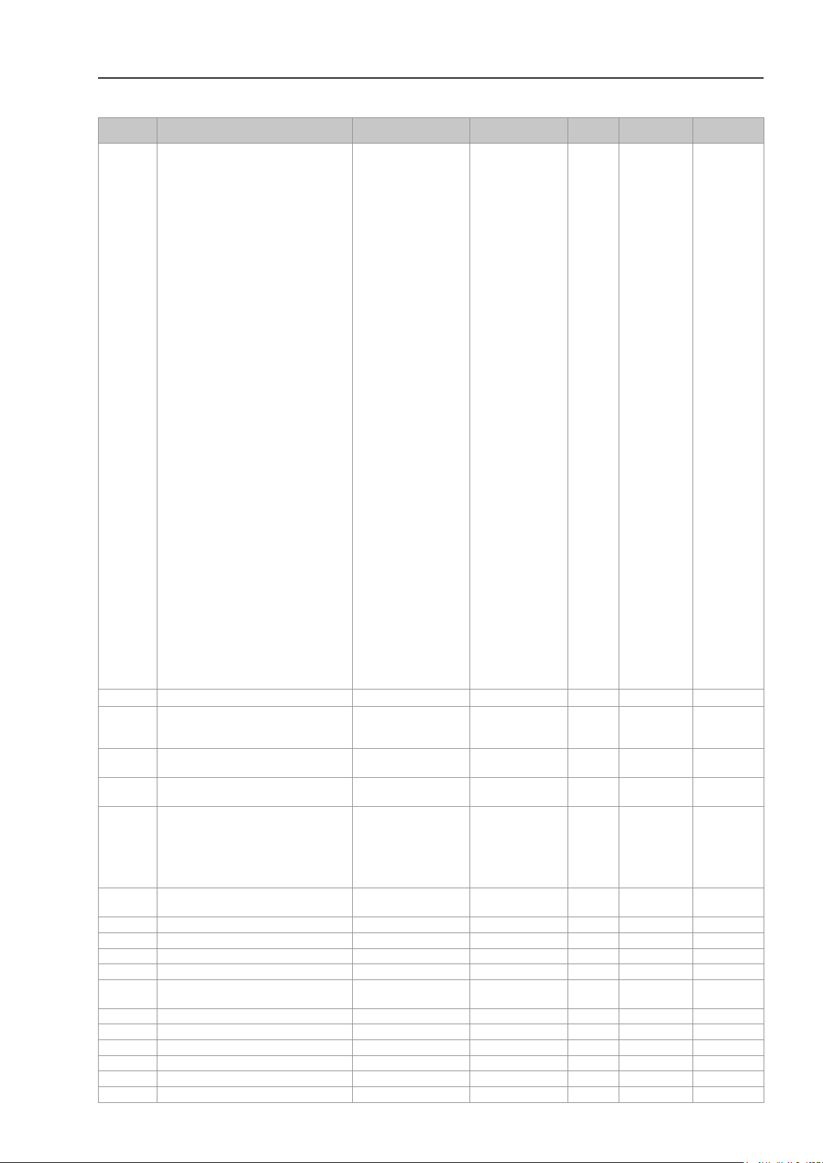
Fault/Alarm Description Possible Causes
F028
Motor Stop Time Exceeded
Motor stop time exceeded fault. Motor being dragged by the load.
Sensorless control with orientation loss.
F098
PM ID Fault
Fault related to the identification of the starting
position in the PM motor control.
Motor shaft spinning during procedure to identify
the starting position.
Setting of P0662 too low for the motor.
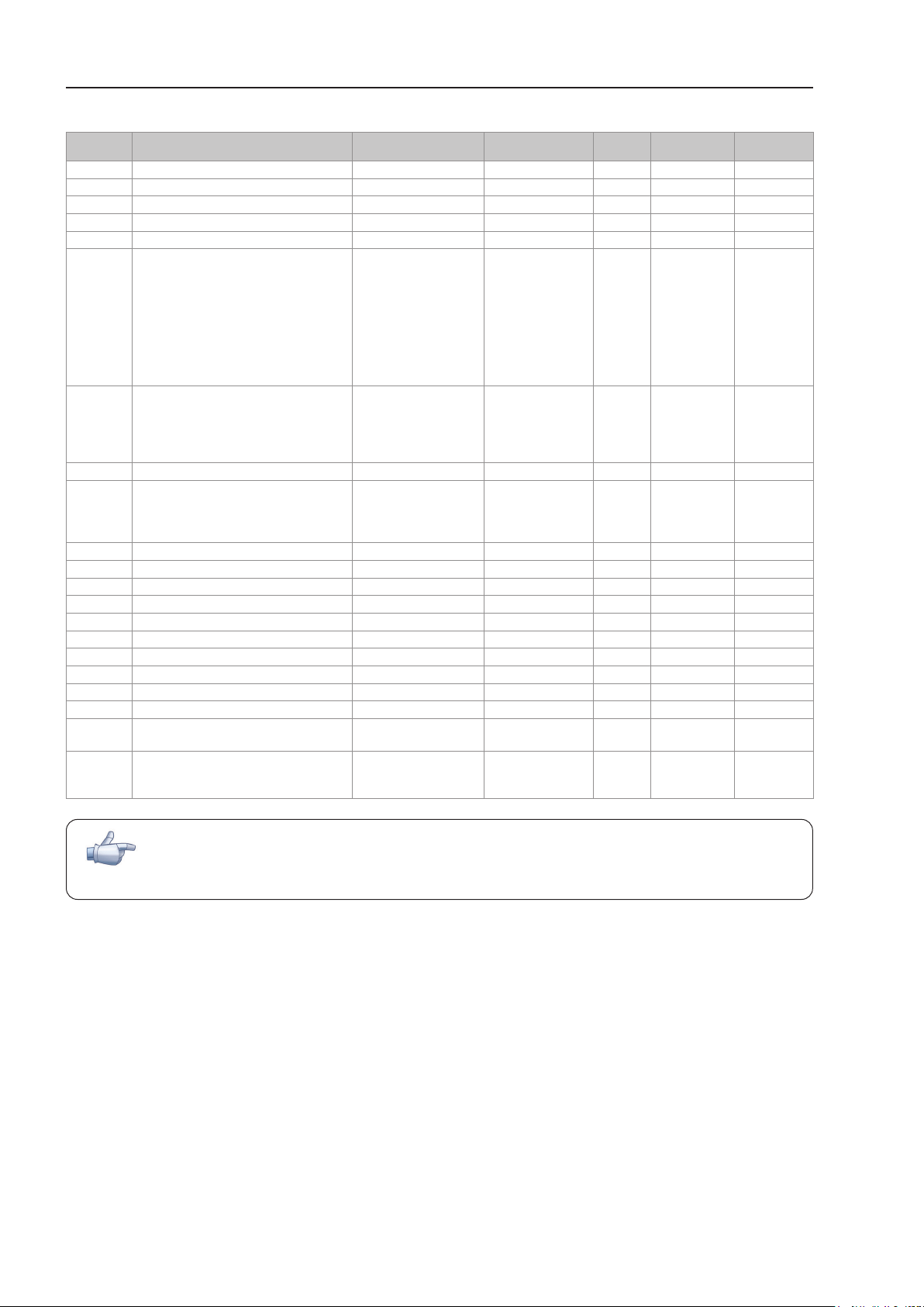
F167
PM Spin Fault
Feedback obtained via encoder does not
match the commanded direction of rotation.
Note:
It may be disabled by setting P0678 = 0.
Motor shaft spinning during procedure to identify
the starting position.
Setting of P0662 too high for the motor.
F168
PM ID Overcurrent
Output overcurrent fault during procedure
to identify the starting position.
Motor shaft spinning during procedure to identify
the starting position.
Setting of P0662 too high for the motor.
F182
Pulse Feedback Fault
Fault in the output pulse feedback. No motor connected or the motor connected to
the inverter output is too small.
Possible defect on the internal circuits of the
inverter.
Possible solutions:
Reset inverter and try again.
Set P0356 = 0 and try again.
A415 (10)
High Temperature on the External Rectifier
Signals related to the setting of parameters
P0832 and P0833.
High ambient temperature around the rectifier
and high output current.
Rectifier heatsink too dirty.
A708
SoftPLC Application Stopped
SoftPLC Application is Not Running. Without SoftPLC application (P1000 = 0 and
P1004 = 1)
SoftPLC Application is stopped (P1001 = 0 and
P1000 = 3).
SoftPLC status indicates application incompatible
with the CFW11 firmware version.
F709
SoftPLC Application Stopped
SoftPLC Application is Not Running. Without SoftPLC application (P1000 = 0 and
P1004 = 2)
SoftPLC Application is stopped (P1001 = 0 and
P1000 = 3).
SoftPLC status indicates application incompatible
with the CFW11 firmware version.
F711
SoftPLC Execution Failed
SoftPLC Execution Failed. Incompatible application.
Uploading of the application failed.
Program generated with an old version of the WLP.
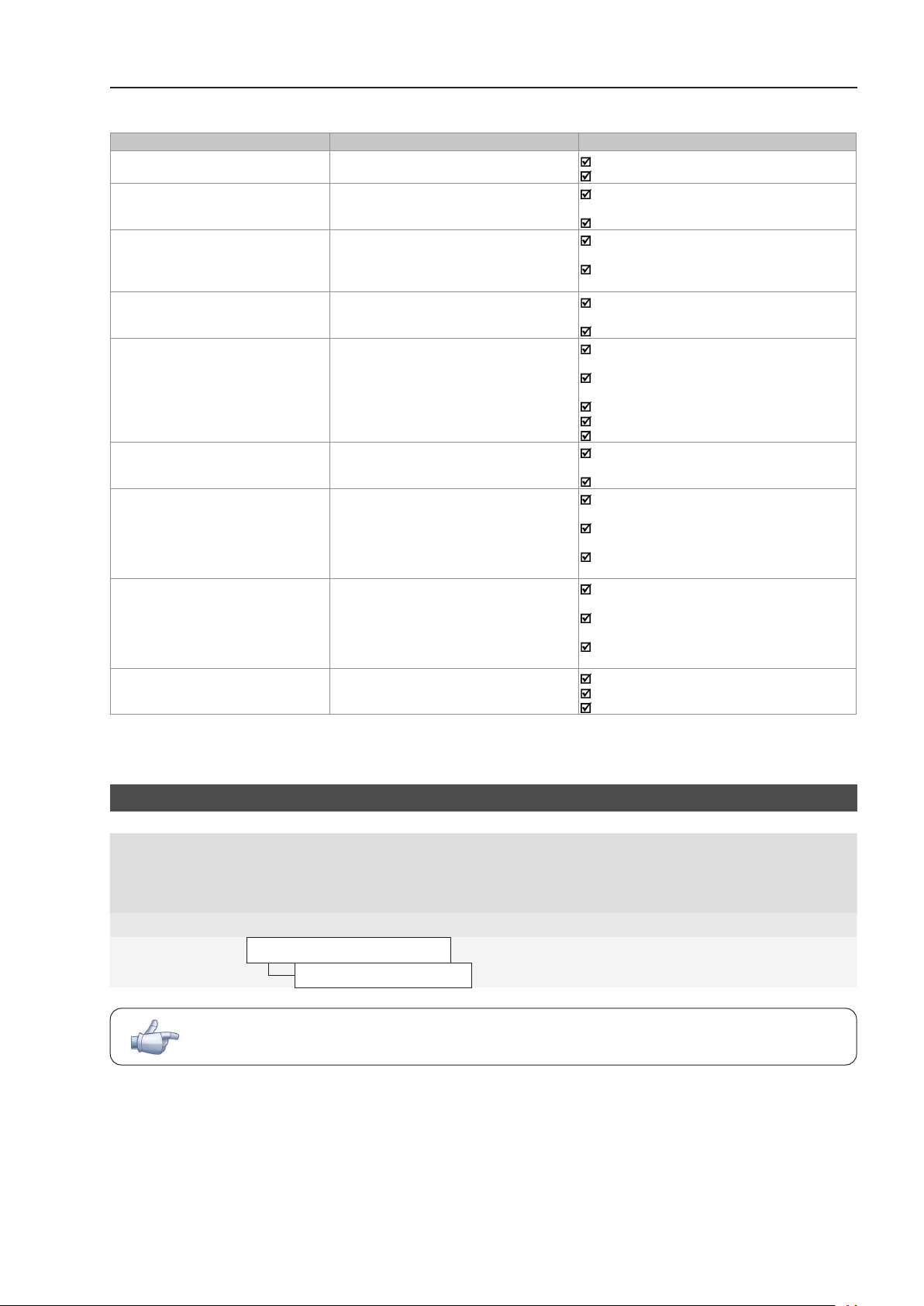
5.4 HMI [30]
P0201 - Language
Adjustable
Range:
0 = Português
1 = English
2 = Español
3 = Deutsch
Factory
Setting:
0
Properties:
Access Groups
via HMI:
01 PARAMETER GROUPS
30 HMI
NOTE!
French language removed.

CFW11 | 8
Addendum to the Programming Manual CFW-11 V5.8X
8 AVAILABLE CONTROL TYPES
8.1 CONTROL TYPES
VVW for PM motor: (Voltage Vector WEG for Permanent Magnet) uses a control method based on the
voltage-oriented vector control technique for permanent magnet motors with good performance for systems
with slow dynamics.
9 SCALAR CONTROL (V/F)
Permanent magnet synchronous motors can be driven with scalar control. To that end, simply set P0396 = 1
during the oriented START-UP.
9.1 V/F CONTROL [23]
P0138 - Slip Compensation
NOTE!
Not used if P0396 = 1.
P0202 - Control Type
Note:
Proper setting of P0400 ensures that the correct V/f ratio will be applied to the output for motors with
voltage at 50 Hz or 60 Hz different from the inverter input voltage.
P0202 = 2 for special motors with rated frequency other than 50 Hz or 60 Hz or for adjusting special
V/f curve profiles. E.g.: approximation of quadratic V/f curve for energy saving in the drive of loads with
variable torque such as centrifugal pumps and fans.
For driving permanent magnet synchronous motors in the V/F mode (VVW PM), select P0202 = 2 and
P0396 = 1.
9.2.1 V/F CONTROL FOR PERMANENT MAGNET SYNCHRONOUS MOTORS (VVW PM)
The VVW PM (Voltage Vector WEG for Permanent Magnet) control mode uses a control method based on the
voltage-oriented vector control technique for permanent magnet motors with good performance for slow dynamics
systems. This control is user-friendly and provides high performance, reducing losses and saving energy, due
to the tracking of the maximum torque per ampere and the maintainability of current stability, according to the
block diagram shown below in Figure 9.1 on page 9.

CFW11 | 9
Addendum to the Programming Manual CFW-11 V5.8X
DC Link Regulation
Current stabilizer
i0 P0003 Calculation of i0
iV, iw
iV, iw
iV, iwi0
Ud
Ramp Hold
P0150=0 or P0150=2
P0151
Hold
P0134
P0133
Zero
P0135
Output
current
limitation
P0448=0 or
P0451>f0
+
+-
fr
fUd
f
f
VV/f curve
Ia
t
P0100-P0104
P0151
Ramp acceleration
P0150=1 or P0150=3
P0152
P0151 UdUd
fUd
P0142
P0143
P0144
P0136
P0444
P0448 Gain P0452 ldq dq
angle,
sextant
PWM
space vector
modulation
PWM
Direction
of rotation
P0454
Ud P0004
Power supply
t
m
TMTPA
P0445 I
VW
P0446 ≠ 0
and
P0451 < f0mP0007
f0P0002
P0147
P0146
P0145
Figure 9.1 - VVW PM control block diagram
Therefore, this strategy eliminates two problems inherent to permanent magnet synchronous motors:
Instability with oscillatory responses in their electrical variables or loss of synchronism after changes in the
load and/or speed reference.
Excessive current for load application.
In this control strategy no self-tuning is required; however, to achieve a good regulation, the motor nameplate
data must be entered into the oriented START-UP. This type of control is ideal for medium and high speed
applications which do not require a fast dynamic response, focused on energy efficiency such as the driving of:
Fans.
Pumps.
Compressors.
On the other hand, the VVW PM is not recommended for applications requiring fast dynamic response or precise
torque control, focused on dynamic performance such as:
Dynamometers.
Cargo handling (such as overhead cranes, hoists, elevators).
Applications requiring performance similar to servomotors, such as CNC machines and machine tools
(positioning and high dynamics required).

CFW11 | 10
Addendum to the Programming Manual CFW-11 V5.8X
NOTE!
The motor rated current must be higher than 1/3 of the inverter rated current.
The VVW PM control mode is selected through parameters P0202 = 2 and P0396 = 1. This control requires
just the motor nameplate data for its proper operation. Besides, it is recommended that the driven motor match
the inverter, that is, the motor and inverter power be as close as possible.
The setting of the VVW PM control is simplified by the HMI STARTUP menu, where the relevant parameters for
the VVW PM configuration are selected to navigate the HMI.
The configuration and setting parameters of the VVW PM control are described here. This information is obtained
on the WEG motor nameplate.
P0396 - Motor Type
Adjustable
Range:
0 = Induction
1 = PMSM (VVW PM)
Factory
Setting:
0
Properties: CFG, V/F and Adjustable V/F
Access Groups
via HMI:
01 PARAMETER GROUPS
43 MOTOR DATA
Description:
It defines the motor type for scalar control.
P0398 - Motor Service Factor
P0400 - Motor Rated Voltage
P0401 - Motor Rated Current
P0402 - Motor Rated Speed
P0404 - Motor Rated Power
P0406 - Motor Cooling
Description:
For further details, see Section 11.7 MOTOR DATA of the programming manual.

CFW11 | 11
Addendum to the Programming Manual CFW-11 V5.8X
P0431 - Number of Poles
Adjustable
Range:
2 to 24 Factory
Setting:
6
Properties: CFG, V/F, V/F Adjustable
Access Groups
via HMI:
01 PARAMETER GROUPS
43 MOTOR DATA
Description:
It sets the motor number of poles.
P0444 - Electromotive Constant KeCT
Adjustable
Range:
0 to 3000 V/kRPM Factory
Setting:
100
Properties: CFG, V/F, V/F Adjustable
Access Groups
via HMI:
01 PARAMETER GROUPS
43 Motor Data
Description:
It sets the magnet induced RMS line voltage as a function of the motor speed. For example: P0444 = 100V/krpm.
Therefore, if the motor is spinning at 1000 rpm, the motor induced voltage will be 100 V.
If P0444 = 0, the considered V/krpm ratio will be 1000 x P0400 / P0402.
9.2.2.1 Parameters For Setting The VVW PM Control
P0445 - MTPA Adjustment Gain
Adjustable
Range:
0.00 to 4.00 Factory
Setting:
0.50
Properties: CFG, V/F Adjustable
Access Groups
via HMI:
01 PARAMETER GROUPS
24 V/F Curve Adjust.
Description:
This parameter can be set by checking the calculated power factor (P0011) and the motor output current (P0003).
Depending on the application, a reactive reduction setting can be obtained, increasing the motor power factor and
reducing the output current.
P0446 - Proportional Gain of the MTPA Regulator
Adjustable
Range:
0 to 500 Factory
Setting:
100
Properties: CFG, V/F Adjustable
Access Groups
via HMI:
01 PARAMETER GROUPS
24 V/F Curve Adjust.

CFW11 | 12
Addendum to the Programming Manual CFW-11 V5.8X
P0447 - Integral Gain of the MTPA Regulator
Adjustable
Range:
0 to 500 Factory
Setting:
12
Properties: CFG, V/F Adjustable
Access Groups
via HMI:
01 PARAMETER GROUPS
24 V/F Curve Adjust.
Description:
These parameters are gained for dynamic regulation of the motor output voltage adjustment for load variations.
If P0446 = 0, the MTPA control will be disabled.
NOTE!
In most cases, these parameters do not require setting.
P0448 - Current Stabilizer Adjustment
Adjustable
Range:
0 to 3000 Factory
Setting:
750
Properties: CFG, V/F Adjustable
Access Groups
via HMI:
01 PARAMETER GROUPS
24 V/F Curve Adjust.
Description:
This gain eliminates instability with oscillatory responses in currents and speed, and or loss of synchronism, after changes
in load and/or speed reference.
P0451 - Current Stabilizer Initial Speed
Adjustable
Range:
0.0 to 100.0 % Factory
Setting:
2.0 %
Properties: CFG, V/F Adjustable
Access Groups
via HMI:
01 PARAMETER GROUPS
24 V/F Curve Adjust.
Description:
It determines a percentage of the motor rated speed to enable the motor current stabilization. If P0002 is greater than
P0451 x P0402, the motor stabilization will be enabled.

CFW11 | 13
Addendum to the Programming Manual CFW-11 V5.8X
P0452 - Time constant of the Current Low-Pass filter - DQ
Adjustable
Range:
20 to 5000 ms Factory
Setting:
1 ms
Properties: CFG, V/F Adjustable
Access Groups
via HMI:
01 PARAMETER GROUPS
24 V/F Curve Adjust
Description:
It determines a percentage of the motor rated speed to enable the motor current stabilization. If P0002 is greater than
P0451 x P0402, the motor stabilization will be enabled.
P0454 - Percentage of the MTPA Minimum Voltage
Adjustable
Range:
0.0 to 100.0 % Padrão: 100 %
Properties: CFG, V/F Adjustable
Access Groups
via HMI:
01 PARAMETER GROUPS
24 V/F Curve Adjust
Description:
This parameter defines the minimum voltage value that will be applied to the motor when the MTPA function is active. This
minimum value is the percentage of the ratio P0435 x Nrpm x 1000.
E.g.:
If P0435 = 120 V/krpm, Nrpm = 900 rpm and P0454 = 50.0 %, the Minimum voltage (V) will be defined by:
(P0454/100)*(P0435*Nrpm)/1000 = 54 V. Where Nrpm is the motor speed in revolutions per minute.
9.5 ENERGY SAVING FUNCTION
Function removed in this firmware version.
9.7 START-UP IN THE VVW PM MODE
NOTE!
Read all the CFW-11 user manual before installing, powering up or operating the inverter.
Sequence for installation, verification, power-up and start-up:
a) Install the inverter according to Chapter 3 - Installation and Connection of the CFW-11 user manual, making
all the power and control connections.
b) Prepare the drive and power up the inverter according to Section 5.1 - Prepare for Start-up of the CFW-11
user manual.
c) Set the password P0000 = 5 according to Section 5.3 PASSWORD SETTING IN P0000.

CFW11 | 14
Addendum to the Programming Manual CFW-11 V5.8X
d) Upload the factory setting at P0204 = 5 and repeat the previous step to set the password.
e) Set the inverter to operate with the line and the motor of the application through the “Oriented Start-up” Menu,
accessing P0317 and changing its content to 1, which causes the inverter to start the “Oriented Start-up” routine .
The "Oriented Start-up" routine displays the main parameters on the HMI in a logical sequence. The setting of
these parameters prepares the inverter for operation with the line and motor of the application. Check the step
by step sequence in Figure 9.1 on page 9
During the "Oriented Start-up" routine, the “Config” (Configuration) status will be indicated on the top left of
the HMI.
f) Set the specific parameters and functions for the application by programming the digital and analog inputs
and outputs, HMI keys, etc., according to the application requirements.
For:
- Simple applications that can use the factory default settings of the analog and digital inputs and outputs, use
the “Basic Application” Menu. See item 5.2.3 - Setting Basic Application Parameters of the CFW-11 user manual.
- Applications that require just the analog and digital inputs and outputs with programming different from the
factory default, use the “I/O Configuration” Menu.
- Applications that require functions such as Flying Start, Ride-Through, DC Braking, Rheostatic Braking, etc.,
access and change the parameters of those functions in the "Parameter Groups" Menu.
For a better view of the start-up in the VVW PM mode, see Figure 9.14 below.

CFW11 | 15
Addendum to the Programming Manual CFW-11 V5.8X
Seq. Action/Result Display Indication
1
- Monitoring Mode.
- Press "Menu" (right "soft
key").
Ready LOC 0rpm
13:48 Menu
0 rpm
0,0 A
0,0 Hz
2
- The group "00 ALL
PARAMETERS" is already
selected.
Ready LOC 0rpm
Exit 13:48 Selec.
00 ALL PARAMETERS
01 PARAMETER GROUPS
02 ORIENTED START-UP
03 CHANGED PARAM.
3
- The group "01
PARAMETER GROUPS" is
selected.
Ready LOC 0rpm
Exit 13:48 Selec.
00 ALL PARAMETERS
01 PARAMETER GROUPS
02 ORIENTED START-UP
03 CHANGED PARAM.
4
-The group "02
ORIENTED START-UP" is
then selected.
- Press "Select".
Ready LOC 0rpm
Exit 13:48 Selec.
00 ALL PARAMETERS
01 PARAMETER GROUPS
02 ORIENTED START-UP
03 03CHANGED PARAM.
5
- The parameter
"Oriented Start-up
P0317: No" is already
selected.
- Press "Select".
Ready LOC 0rpm
Exit 13:48 Selec.
Oriented Start-up
P0317: No
6
- The content of
"P0317 = [000] No" is
showed.
Ready LOC 0rpm
Exit 13:48 Save
P0317
Oriented Start-up
[000] No
7
- The content of the
parameter is changed to
"P0317 = [001] Yes"
- Press "Save".
Ready LOC 0rpm
Exit 13:48 Save
P0317
Oriented Start-up
[001] Yes
8
- In this moment the
Oriented Start-up routine
is initiated and the
"Config" status is
indicated at the top left
part of the keypad (HMI).
- The parameter
"Language P0201:
English" is already
selected.
- If necessary, change the
language by pressing
“Select", next
and to select the
language and then press
"Save".
Config LOC 0rpm
Reset 13:48 Selec.
Language
P0201: English
Control Type
P0202: V/F 60Hz
Seq. Action/Result Display Indication
9
- Set the content of
P0202 pressing "Select".
-Next press
until selecting the option
"[002] V/f Adjustable",
and then press "Save".
Config LOC 0rpm
Reset 13:48 Selec.
Language
P0201: English
Control Type
P0202: V/F 60Hz
Config LOC 0rpm
Exit 13:48 Save
P0202
Control Type
[002] V/f Adjustable
10
- If necessary, change
the content of P0296
according to the used line
voltage. Therefore press
"Select". This change will
affect P0151, P0153,
P0185, P0321, P0322,
P0323 and P0400.
Config LOC 0rpm
Reset 13:48 Selec.
Control Type
P0202: VVW
Line Rated Voltage
P0296: 440 - 460 V
11
- If necessary, change
the content of P0298
according to the inverter
application. To do that,
press "Select". This
change will affect P0156,
P0157, P0158, P0401,
P0404 and P0410.
(the latter only if P0202
= 0.1 or 2 V/f modes).
The time and performance
level of the overload
protection will also be
affected.
Config LOC 0rpm
Reset 13:48 Selec.
Line Rated Voltage
P0296: 440 - 460 V
Application
P0298: Normal Duty (ND)
12
- Set the content of P0396
by pressing "Select".
- Then press
until selecting the
option "[001] PMSM (VVW
PM)" and then press
"save".
Config LOC 0rpm
Reset Selec.
Application
P0298: Normal Duty
(ND) Motor Type
P0396:Induction
Config LOC 0rpm
Exit Save
Motor Type
P0396
{001} PMSM (VVW PM)
13
- If necessary, set the
content of P0398
according to the motor
service factor. To do that,
press "Select".
This change will affect
the current value and
the operating time of the
motor overload function.
Config LOC 0rpm
Reset 13:48 Selec.
Motor Type
P0396: PMSM (VVW PM)
Motor Service Factor
P0398: 1,15

CFW11 | 16
Addendum to the Programming Manual CFW-11 V5.8X
Seq. Action/Result Display Indication
14
- If necessary, set the
content of P0400
according to the motor
rated voltage. To do that,
press "Select".
Config LOC 0rpm
Reset 13:48 Selec.
Motor Service Factor
P0398: 1.15
Motor Rated Efficiency
P0400: 440 V
15
- If necessary, change
the content of P0401
according to the motor
rated current. To do
that, press "Select". This
change will affect P0156,
P0157 and P0158.
Config LOC 0rpm
Reset 13:48 Selec.
Motor Rated Voltage
P0400: 440 V
Motor Rated Current
P0401: 13,5 A
16
- If necessary, change
the content of P0402
according to the motor
rated speed. Therefore
press "Select". This
change will affect P0122
to P0131, P0133, P0134,
P0208, P0288, P0289,
P0403 and P0135.
Config LOC 0rpm
Reset 13:48 Selec.
Motor Rated Current
P0401: 13.5 A
Motor Rated Speed
P0402: 1750 rpm
17
- P0403 is automatically
set according to:
P0403 = P0402 x P0431
120
To do that, press “Select".
Config LOC 0rpm
Reset 13:08 Selec.
Motor P0402: 1750 rpm
Motor Rated Frequency
P0403: 60 Hz
18
- If necessary, change
the content of P0404
according to the motor
rated power. To do that,
press "Select".
Config LOC 0rpm
Reset 13:48 Selec.
Motor Rated Frequency
P0403: 60 Hz
Motor Rated Power
P0404: 7,5 CV
Seq. Action/Result Display Indication
19
- Parameter P0405 will
only be visible if the ENC1
encoder board or PLC11
module is connected to
the inverter.
- Set P0405 according to
the number of pulses per
encoder rotation. To do
that, press "Select".
Config LOC 0rpm
Reset 13:48 Selec.
Motor Rated Power
P0404: 7,5 CV
Encoder Pulse Number
P0405: 1024 ppr
20
- If necessary, change
P0406 according to the
type of motor ventilation.
To do that, press “Select".
Config LOC 0rpm
Reset 13:48 Selec.
Encoder Pulse Number
P0405: 1024 ppr
Motor Ventilation
P0406: Selfventilated
21
- Set P0431 to 6 for
standard Wmagnet motor.
To do that, press "Select".
Such change will affect
P0403.
Config LOC 0rpm
Reset 13:48 Selec.
Motor Ventilation
P0496: Selfventilated
Number of Poles
P0431: 6
22
- Set P0444 according to the
nameplate data.
To do that, press
"Select"
.
- To finish the Oriented
Start-up routine, press
"Reset". (Left soft key) or
Config LOC 0rpm
Reset 13:48 Selec.
Number of Poles
P0431: 6
Ke Constant - CT
P0444: 100
23
- After some seconds,
the display returns to the
monitoring mode.
Ready LOC 0rpm
13:48 Menu
0 rpm
0.0 A
0.0 Hz
Figura 9.2 - Oriented start-up of the VVW PM mode

CFW11 | 17
Addendum to the Programming Manual CFW-11 V5.8X
10.1 VVW CONTROL [25]
P0397 - Slip Compensation
Adjustable
Range:
0 = Disable
1 = Enable Motorizing/Regenerating
2 = Enable Motorizing
3 = Enable Regenerating
Factory
Setting:
1
Properties: CFG and VVW
Access Groups
via HMI:
01 PARAMETER GROUPS
25 VVW Control
Description:
It enables or disables the slip compensation when it is motorizing or regenerating in the VVW control mode. See parameter
P0138 in Section 9.1 V/F CONTROL [23] for further details on slip compensation.
11.8.8 DROOP FUNCTION [90]
Function removed in this firmware version.
15 FAULTS AND ALARMS
15.3 PROTECTIONS [45]
P0156 - Motor Overload Current at 100 % Rated Speed
P0157 - Motor Overload Current at 50 % Rated Speed
P0158 - Motor Overload Current at 5 % Rated Speed
Note:
When P0202 = 6 or 7, parameters P0156, P0157 and P0158 will be adjusted during the Oriented Start-up routine
to 1.05 x P0401.

CFW11 | 18
Addendum to the Programming Manual CFW-11 V5.8X
P0354 - Heatsink Fan Protection Configuration
Adjustable
Range:
0 = Alarm
1 = Fault
0 = Inactive
Factory
Setting:
1
Properties: CFG
Access Groups
via HMI:
01 PARAMETER GROUPS
45 Protections
Description:
Table 15.7 - Actions for the options of parameter P0354
P0354 Action
0 = Alarm Enables alarm (A178). The inverter will not be disabled when the alarm occurs.
1 = Fault Enables fault (F179). The inverter will be disabled when the fault occurs.
2 = Inactive The protection of the the heatsink fan speed is disabled.
P0362 - Motor Stop Fault Time
Adjustable
Range:
0 to 999 s Factory
Setting:
20 s
Properties: V/f, VVW, Vector and PM
Access Groups
via HMI:
01 PARAMETER GROUPS
20 Ramps
Description:
This parameter defines the time to generate the F028 fault in the motor stop command. The inverter will indicate F028
if the motor stop time exceeds the sum of the value programmed in the deceleration ramps (P101/P103) and the time
programmed in P0362.
To disable fault F028, set P0362 = 0.
P0678 - Check Encoder Direction of Rotation
Adjustable
Range:
0 to 200 rpm Factory
Setting:
0 rpm
Properties: CFG, PM with encoder
Access Groups
via HMI:
01 PARAMETER GROUPS
45 Protections
Description:
This parameter defines the speed at which it will be checked whether the direction of rotation of the motor shaft is consistent
with the reference direction of rotation.
The direction of rotation of the motor shaft is only checked when the PM control with encoder (P0202 = 6) is being used.
If the direction of rotation of the motor shaft is different from the reference direction of rotation, a fault will occur (F167).
When set to 0 rpm, the direction of rotation of the motor shaft is not checked.

CFW11 | 19
Addendum to the Programming Manual CFW-11 V5.8X
17 COMMUNICATION [49]
17.3 ANYBUS-CC INTERFACE
P0741 - Profibus Data Profile
P0760 - PROFIdrive Output Current
P0761 - PROFIdrive Output Power
P0762 - PROFIdrive Output Torque
P0763 - Status Word Namur PROFIdrive
P0840 - Anybus Status
P0841 - Ethernet Baud Rate
P0842 - Modbus TCP Timeout
P0843 - IP Address Configuration
P0844 - IP1 Address
P0845 - IP2 Address
P0846 - IP3 Address
P0847 - IP4 Address
P0848 - CIDR
P0849 - Gateway 1
P0850 - Gateway 2
P0851 - Gateway 3
P0852 - Gateway 4
P0853 - Suffix for Station Name
P0854 - Compatibility Mode
This manual suits for next models
1
Table of contents
Languages:
Other Weq Inverter manuals
Popular Inverter manuals by other brands

Gardigo
Gardigo 70095 operating instructions

SolaX Power
SolaX Power X3-Retro Fit Series Quick installation guide

Huawei
Huawei SUN2000-8KTL Quick installation guide

Briggs & Stratton
Briggs & Stratton QuietPower Q6500 Quick start up guide

Dometic
Dometic TEC29 EV AUS installation manual

KROHNE
KROHNE OPTIFLUX Series Supplementary instructions

Mitsubishi Electric
Mitsubishi Electric FR-HEL-N280K instruction manual

Atlas Copco
Atlas Copco QAX 12 Dd S2 APP instruction manual

York
York YVAG012 Operation & maintenance manual

Xantrex
Xantrex XPower 450 owner's manual

FRONIUS
FRONIUS xPrimo GEN24 4.0 Plus operating instructions

SOLIS
SOLIS S5-GC75K-US user manual