Allgemeiner Teil / General Section GDV 200
1 - 4 GRUNDIG Service
Ausbauhinweise (Netzstecker ziehen)
Öffnen der Schublade bei defektem Laufwerk
– Laufwerk ausbauen (Pkt. 7).
– Schieber A(Fig. 6) bis zum Anschlag nach links schieben.
– Die Schublade kann jetzt herausgezogen werden.
1. Gehäuseoberteil
– 7 Schrauben Fherausdrehen (Fig. 2).
– Gehäuseoberteil abnehmen.
2. Frontblende
– 2 Schrauben Eherausdrehen (Fig. 1).
– Rasthaken I(Fig. 4) lösen und Frontblende abnehmen.
– Gegebenenfalls Steckverbindungen lösen.
3. Bedieneinheit ausbauen
– 3 Schrauben Mund 4 Schrauben J(Fig. 5) herausdrehen.
– 3 Rasthaken K(Fig. 5) lösen und durch die Platine drücken.
– Seitenteil Nabnehmen (Fig. 5).
– Bedieneinheit an der Unterseite anheben und aus der Blende
nehmen.
Einbauhinweis:
– 2 Passstifte Ldes Lichtleiters und 3 Rasthaken Kdes Einschalt-
knopfes in die Aussparungen der Bedieneinheit stecken und mit je
4 Schrauben Jund 4 Schrauben Mbefestigen.
4. A/V-MUX-Platte ausbauen
– 7 Schrauben H(Fig. 3) herausdrehen.
– 2 Rastnasen A(Fig. 1) lösen und A/V-MUX-Platte aus dem Gerät
nehmen.
– Gegebenenfalls Steckverbindungen lösen.
6. Netzteil ausbauen
– 2 Schrauben D(Fig. 1) und Schraube G(Fig. 3) herausdrehen.
– 2 Rastnasen C(Fig. 1) lösen und Netzteil aus dem Gerät nehmen.
– Gegebenenfalls Steckverbindungen lösen.
7. Laufwerk ausbauen (CD-Laufwerk)
– 4 Schrauben B(Fig. 1) herausdrehen.
– Laufwerk in Richtung Geräterückseite aus dem Gerät nehmen.
– Gegebenenfalls Steckverbindungen lösen.
7.1 DVD-Monoboard ausbauen
– 4 Schrauben I(Fig. 6) herausdrehen und DVD-Monoboard ab-
nehmen.
– Gegebenenfalls Steckverbindungen lösen.
Achtung: Die Lasereinheit ist sehr empfindlich gegen statische
Aufladungen (MOS-Bauteile)!
Schließen Sie deshalb die Flexprintleitung zur
Lasereinheit vor dem Abziehen mit einer Bü-
roklammer kurz.
7.2 Laufwerk ausbauen
– DVD-Monoboard ausbauen (Pkt. 7.1).
– 2 Schrauben B(Fig. 6) herausdrehen.
– 4 Gummipuffer C(Fig. 6) aushängen und die Laufwerksmechanik
vorsichtig in Pfeilrichtung herausziehen.
Montagehinweis zum Einbau eines neuen Laufwerks:
– Flexprint an der Lasereinheit anschließen.
– offenes Ende des Flexprint mit einer Büroklammer kurz schließen
(MOS-Schutz).
– werkseitig angebrachte Schutzlötstellen der Lasereinheit entfernen
(Fig. 8).
7.3 Laufwerk zerlegen
– Laufwerk ausbauen (Pkt. 7.2).
7.3.1 Schublade ausbauen
– Schieber A(Fig. 6) bis zum Anschlag nach links schieben.
– Schublade herausziehen.
– Rastnase E(Fig. 7) vorsichtig mit einem kleinen Schraubendreher
anheben und Schublade ganz herausziehen.
7.3.2 Lasereinheit ausbauen
– 4 Rastnasen F(Fig. 9) ausrasten und DVD-Abdeckung Gabneh-
men.
– Bügel I(Fig. 10) ausrasten und Lasereinheit Jherausnehmen.
Beim Wiedereinbau auf korrekten Sitz der Lasereinheit in den
Führungen K(Fig. 11) achten!
7.3.3 Lademotor ausbauen
– Riemen H(Fig. 10) abnehmen.
– Bügel D(Fig. 6) ausrasten und Lademotor herausnehmen.
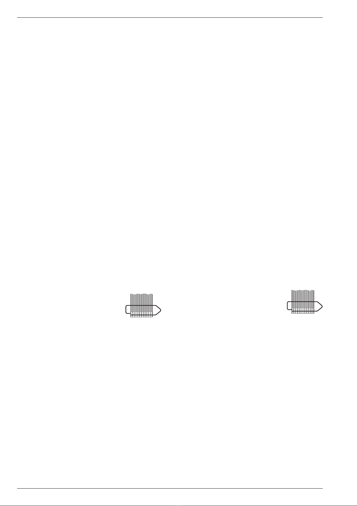
FLEXPRINT
Disassembly Instructions (Disconnect the mains plug)
Opening the Tray when the Drive is defective
– Remove the Drive Mechanism (para 7).
– Push the slider A(Fig. 6) to the left until its stop.
– The tray can be pulled out now.
1. Cabinet Upper Part
– Undo 7 screws F(Fig. 2).
– Remove the upper part of the cabinet.
2. Front Panel
– Undo 2 screws E(Fig. 1).
– Release the catches I(Fig. 4) and remove the front panel.
– Unplug the connectors if necessary.
3. Removing the Keyboard Control Unit
– Undo 3 screws Mand 4screws J(Fig. 5).
– Release the 3 catches K(Fig. 5) and push them through the board.
– Remove the side part N(Fig. 5).
– Lift the keyboard control unit at its bottom side and remove it from the
trimplate.
Fitting Instructions:
– Insert the 2 locating pins Lof the optical fibre lead and the 3 catches
Kof the power-on button into the cutouts in the control unit and fix
them with the 4 screws Jand 4 screws M, respectively.
4. Removing the A/V-MUX Board
– Undo 7 screws H(Fig. 3).
– Disengage the 2 locking lugs A(Fig. 1) and remove the A/V-MUX
Board.
– Unplug the connectors if necessary.
6. Removing the Power Supply
– Undo the 2 screws D(Fig. 1) and the screw G(Fig. 3).
– Disengagethe2locking lugs C(Fig. 1) andremovethepower supply
from the unit.
– Unplug the connectors if necessary.
7. Removing the Drive Mechanism (CD Drive)
– Undo 4 screws B(Fig. 1).
– Push the CD drive to the back of the cabinet and remove it.
– Unplug the connectors if necessary.
7.1 Removing the DVD-Monoboard
– Undo 4 screws I(Fig. 6) and remove the DVD-Monoboard.
– Unplug the connectors if necessary.
Attention: The laser unit is very sensitive to
static charges (MOS components)!
Therefore, short-circuit the Flexprint to the
laser unit with a paper clip before discon-
necting it.
7.2 Disassembling the Drive Mechanism
– Remove the DVD-Monoboard (para 7.1).
– Undo 2 screws B(Fig. 6).
– Unhook the 4 rubber shock-mounts C(Fig. 6) and pull out carefully
the drive mechanism in direction of the arrow.
Instructions for Mounting a new Drive Mechanism:
– Connect the Flexprint to the laser unit.
– Short the open end of the Flexprint with a paper clip (MOS
protection).
– Remove the factory-applied protective soldering joints from the
laser unit (Fig. 8).
7.3 Disassembling the Drive Mechanism
– Remove the drive mechanism (para 7.2).
7.3.1 Removing the Tray
– Push the slider A(Fig. 6) to the left until its stop.
– Pull the tray out.
– Carefully lift the locking lug E(Fig. 7) with a small screw driver and
pull the tray out completely.
7.3.2 Removing the Laser Unit
– Disengage the 4 locking lugs F(Fig. 9) and remove the DVD
cover G.
– Unhook the clip I(Fig. 10) and remove the Laser Unit J.
When reassembling, the laser unit must fit in the guides K
(Fig. 11)!
7.3.3 Removing the Loading Motor
– Remove the belt H(Fig. 10).
– Unhook the clip D(Fig. 6) and remove the loading motor.
FLEXPRINT