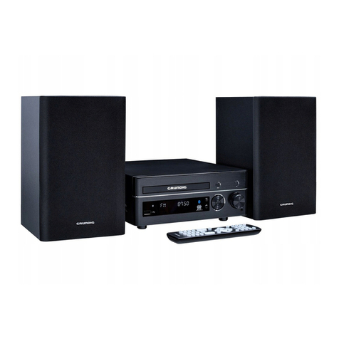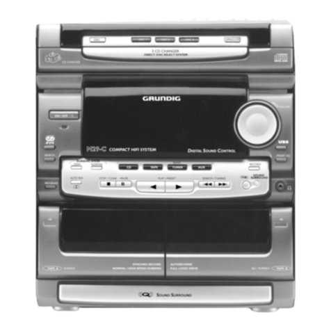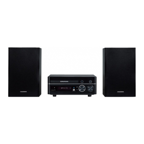
Allgemeiner Teil / General Section UMS 4100, UMS 4101
1 - 2 GRUNDIG Service
Es gelten die Vorschriften und Sicherheitshin-
weise gemäß dem Service Manual "Sicherheit",
Materialnummer 720108000000, sowie zusätz-
lich die eventuell abweichenden, landes-
spezifischen Vorschriften!
The regulations and safety instructions shall be
validasprovidedbythe"Safety"ServiceManual,
part number 720108000000, as well as the re-
spective national deviations!
Table of Contents
Page
General Section ............................ 1 - 2 … 1 - 15
Measuring Instruments / Equipment .......................................... 1 - 2
Technical Data ........................................................................... 1 - 3
Service Hints .............................................................................. 1 - 3
Disassembly Instructions ........................................................... 1 - 4
Operating Hints ........................................................................ 1 - 12
Adjustment Procedures..................2 - 3 ... 2 - 4
Layout of PCBs
and Circuit Diagrams ................... 3 - 1 … 3 - 23
Block Diagram ............................................................................ 3 - 1
Wiring Diagram .......................................................................... 3 - 2
Circuit Diagrams:
Amplifier Part .......................................................................... 3 - 6
Tuner Part .............................................................................. 3 - 8
CD and Processor Part ........................................................ 3 - 14
Cassette Part (only UMS 4101) ........................................... 3 - 16
Mains Unit ............................................................................ 3 - 19
Display PCB ......................................................................... 3 - 20
Keyboards UMS 4100 .......................................................... 3 - 22
Keyboards UMS 4101 .......................................................... 3 - 23
Layout of the PCBs:
Amplifier Part .......................................................................... 3 - 4
Tuner Part ............................................................................ 3 - 10
CD and Processor Part ........................................................ 3 - 12
Cassette Part (only UMS 4101) ........................................... 3 - 18
Mains Unit ............................................................................ 3 - 19
Display PCB ......................................................................... 3 - 21
Keyboards UMS 4100 .......................................................... 3 - 22
Keyboards UMS 4101 .......................................................... 3 - 23
Exploded Views and
Spare Parts Lists ............................ 4 - 1 … 4 - 8
Exploded View UMS 4100 ......................................................... 4 - 1
Spare Parts List UMS 4100 ....................................................... 4 - 5
Exploded View UMS 4101 ......................................................... 4 - 3
Spare Parts List UMS 4101 ....................................................... 4 - 7
Inhaltsverzeichnis
Seite
Allgemeiner Teil ........................... 1 - 2 … 1 - 11
Messgeräte / Messmittel ............................................................ 1 - 2
Technische Daten ...................................................................... 1 - 3
Servicehinweise ......................................................................... 1 - 3
Ausbauhinweise ......................................................................... 1 - 4
Bedienhinweise .......................................................................... 1 - 8
Abgleichvorschriften ......................2 - 1 ... 2 - 2
Platinenabbildungen
und Schaltpläne ........................... 3 - 1 … 3 - 23
Blockschaltplan .......................................................................... 3 - 1
Verdrahtungsplan ....................................................................... 3 - 2
Schaltpläne:
Verstärkerteil .......................................................................... 3 - 6
Rundfunkteil ........................................................................... 3 - 8
CD- und Prozessorteil .......................................................... 3 - 14
Cassettenteil (nur UMS 4101) .............................................. 3 - 16
Netzteil ................................................................................. 3 - 19
Display-Platte ....................................................................... 3 - 20
Bedien-Platten UMS 4100 .................................................... 3 - 22
Bedien-Platten UMS 4101 .................................................... 3 - 23
Platinenabbildungen:
Verstärkerteil .......................................................................... 3 - 4
Rundfunkteil ......................................................................... 3 - 10
CD- und Prozessorteil .......................................................... 3 - 12
Cassettenteil (nur UMS 4101) .............................................. 3 - 18
Netzteil ................................................................................. 3 - 19
Display-Platte ....................................................................... 3 - 21
Bedien-Platten UMS 4100 .................................................... 3 - 22
Bedien-Platten UMS 4101 .................................................... 3 - 23
Explosionszeichnungen und
Ersatzteillisten ................................ 4 - 1 … 4 - 8
Explosionszeichnung UMS 4100 ............................................... 4 - 1
Ersatzteilliste UMS 4100 ............................................................ 4 - 5
Explosionszeichnung UMS 4101 ............................................... 4 - 3
Ersatzteilliste UMS 4101 ............................................................ 4 - 7
Allgemeiner Teil
Messgeräte / Messmittel
Frequenzzähler Mess-Sender
Wobbelsender Oszilloskop
Digitalvoltmeter Klirrfaktormessgerät
Testcassette 3150Hz/10kHz (z.B. 448)
Beachten Sie bitte das GRUNDIG Messtechnik-Programm, das Sie
unter folgender Adresse erhalten:
General Section
Measuring Instruments / Equipment
Frequency counter Signal generator
Sweep generator Oscilloscope
Digital voltmeter Distortion meter
Test cassette 3150Hz/10kHz (e.g. 448)
Please note the GRUNDIG Catalog "Test and Measuring Equipment"
obtainable from:
GRUNDIG AG Geschäftsbereich Instruments
Test- und Mess-Systeme
Würzburger Str. 150
D 90766 Fürth/Bay
Tel. 0911/703-4540
Fax 0911/703-4130
Internet: http://www.grundig-instruments.de


