Grundig STR 7122 TWIN User manual

ǵ
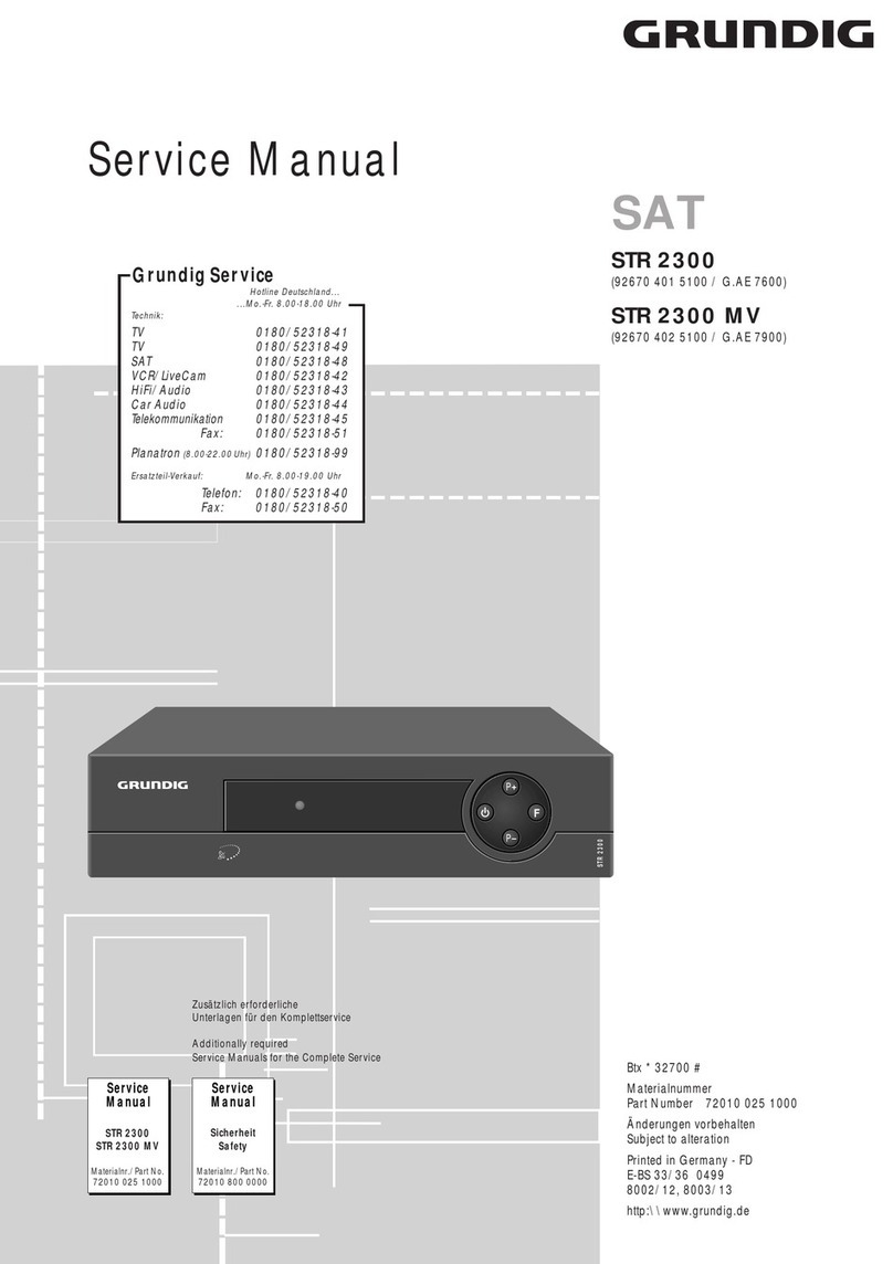
SATELLITE TV RECEIVER
STR 7122 TWIN
DEUTSCH
ENGLISH

CONTENTS__________________________________________________________________________
5 General
Scope of delivery
GRUNDIG accessories for satellite reception systems
6 Special Features
8 Installation and Safety
Installation, safety, environment
9 At a Glance
Front panel
Rear panel
The remote control
Inserting batteries
14 Connecting up and Switching On
How to connect the satellite aerial
Connection via a EURO-AV cable
TV set
Video recorder
Decoder
Connecting up to hifi equipment
Connecting devices via an RF aerial cable
Connecting the satellite receiver to the mains power supply
To switch on from standby mode
18 Reception Unit and Channel Selection
Reception unit A or B selection
Choosing a satellite channel
2

CONTENTS_____________________________________________________________________________
19 Pre-programming
Explanatory notes about the table of stations
20 Sound Settings
Volume control
Setting the sound to mute (sound off)
21 The Menus
The key functions in the menus
The main menu
23 Timer Programming
The »Timer« sub-menu
29 Blocking the Receiver
Blocking the receiver
Unblocking the receiver
31 Settings
“Channel position set-up” sub-menu
“Basic set-up” sub-menu
“LNC set-up” sub-menu
39 LNC Arrangements
Explanation of the LNC arrangements available
ENGLISH
3

CONTENTS_____________________________________________________________________________
4
42 Multi-satellite Reception
Two-satellite reception
LNC selection with DiSEqC
LNC selection with ToneBurst (mini DiSEqC)
46 Adjusting to External Equipment
Tuning the TV set and the video recorder to the satellite receiver
48 Technical Data
49 Trouble Shooting
52 GRUNDIG Service
Subject to alterations and ererrors!

ENGLISH
5
GENERAL ____________________________________________________________________________
Scope of delivery
1 stereo satellite receiver STR 7122 TWIN
1 mains power lead
1 remote control TP 716 SAT
2 1.5 V batteries (type AA) for the remote control
1 user manual
1 table of stations
1 symbol card
Note:
Please consult your dealer if any of these items are missing or damaged.
GRUNDIG accessories for satellite reception systems
Your dealer or technician will be pleased to give you details on GRUNDIG's comprehensive range of
accessories for satellite receiver equipment.
To operate the receiver you will need a suitable satellite aerial, installed and aligned to the required
satellite (eg ASTRA).
The installation and connection of this satellite aerial is a complex task and is best left to a professional.

SPECIAL FEATURES _____________________________________________________________
6
One satellite receiver with two reception units
Dear Customer,
To use the receiver you will need a suitable satellite aerial which must be installed and aligned with
the desired satellite (for example Astra).
The satellite receiver STR 7122 TWIN is fitted with two separate reception units Aand B
(Input Aand Input B).
Both reception units (Aand B) of the satellite receiver must receive the signals from the same
satellite.
Reception unit A(Input A) is provided for TV operation, reception unit B(Input B) for video
operation.
By means of this comprehensive equipment, you may
– Input A: watch one satellite programme on a TV set and
– Input B: record at the same time a second satellite programme on your video recorder,
or
– watch two different satellite programmes on two TV sets.
So that it will be easier for you to make a selection and enter the necessary settings, we have pre-
programmed most of the channel positions available via this satellite receiver using all the settings
required.
The pre-set satellite channel positions available via this receiver are shown separately on the enclosed
table of stations.
This table does not claim to be either complete or fully up-to-date.
Current satellite data can be called up using the Teletext tables of the various satellite channels
(eg SAT 1 or 3SAT Text), or via Internet, and will also be available in any current satellite TV guide.

SPECIAL FEATURES ___________________________________________________
ENGLISH
7
You will, of course, be able to re-programme "new" satellite channels in an easy and straight-
forward way.
The television's on-screen menus provide the dialogue between the user and the receiver.
The receiver will respond to many of the functions selected via the remote control by displaying info
menus and on-screen symbols on the TV screen.
In a simple and understandable way, you will be guided step-by-step to the next setting available.
We have also provided you with a symbol card, which sets out all the symbols used in the menu and
gives an explanation of each one.
Using the sub-menus you can
programme the timer;
lock the satellite receiver;
select and mark your favourite programmes;
change channel position settings, e.g. the transmission frequency,
set the LNC polarity, change sound settings;
choose decoder settings, change the contrast settings;
select and change the basic settings;
make LNC settings;
switch the LNC voltage on/off.

8
INSTALLATION AND SAFETY______________________________________________
In order that you may enjoy this high-quality and comfortable satellite receiver for a long time it
is very important that you observe the following points when installing the receiver.
This satellite receiver is intended for the reception of TV picture and sound signals.
Any other application is expressly prohibited.
If the receiver is exposed to drastic temperature changes, for example when taking it from a cold
to a warm place, connect it to the mains supply and let it stand at the new place for at least
two hours.
Do not expose the satellite receiver to any moisture.
The receiver is intended for use in dry rooms. If you wish to operate it in the open air, make
absolutely sure that it is protected against moisture (rain, splashes of water).
Do not place any object filled with water (vases and similar) on the receiver.
The object might fall over and the liquid spilling into the unit would impair its electrical safety.
Place the receiver on a flat and hard surface. Do not place any objects (e.g. newspapers) on
the receiver.
If placed on a wall-mounted unit, the all-round distance between the receiver and the sides of
the wall unit must be at least 10 cm!
Do not place the receiver in the immediate vicinity of a heat source or in direct sunlight as this would
prevent appropriate cooling.
°C2h
°C
ɩ
ǵ
STR7100
Ǽ
P
P
STR7100
Ǽ
P
P
ɩ
ǵ
STR 7100
Ǽ
P
P
ɩ
ǵ
STR7100
Ǽ
P
P
Krieg im Balkan

ENGLISH
9
INSTALLATION, SAFETY, ENVIRONMENT ______________________________________
Thunderstorms are a danger for any electrical appliance. Even when switched off, the receiver might
be damaged by lightning striking the mains supply and/or the aerial lead. During a thunderstorm
you must always disconnect the mains and aerial plugs.
Never open the receiver. Damage caused by unqualified work is not covered by the manufacturer’s
guarantee.
For this satellite receiver, technology and ecology form a convincing overall idea. Only ecologically
high-grade materials are used. The packing consist of almost 100% recycled paper, its plastic parts
have been reduced to a minimum.
The batteries supplied are free of mercury and cadmium. For environmental reasons no buffer
battery is used.
To enable a high-grade recycling after use, the number of plastic parts has consequently been reduced.
All large plastic parts are marked.
To facilitate service and for optimum recycling, this receiver has been designed in a specially
disassembly-friendly and recycling-friendly way.
Do not dispose of used batteries, also those free of heavy metals, together with domestic waste.
Please dispose of them at the appropriate collection points.
If you are not using the receiver for a lengthy period (including overnight), please switch it over to
standby. This saves energy.
This manual is printed on recycled paper. This helps to protect the environment.
CH.ADJ
AERIAL
MADE IN U.K.
VCR
DECODER
HAZARD-LIVE PARTS
DO NOT REMOVE COVERS
TV
R
L
AUDIO
OUT
13W MAX.
50/60 Hz
230V
INPUT
MAINS
300mA DC
13V/18V
LNC
TV /VCR

10
AT A GLANCE_____________________________________________________________________
Front panel
000011
3-digit display of the channel position number.
Indicators A green »
–
« is lit if the satellite receiver is in standby.
(green/red)
A green »●« is lit if the satellite receiver is switched on.
– The left green »●« is lit if reception unit A(INPUT A) is selected.
– The right green »●« is lit if reception unit B(INPUT B) is selected.
Note:
If the built-in timer is programmed and the receiver is in standby mode, a red
»●« and a green »
–
« are lit.
ǼǼSwitches the receiver to standby, and from standby back to the last selected
channel position (last channel position memory).
P+ Switches on from standby mode. Switches to the next channel position step-by-step.
P
-
Switches on from standby mode and step-by-step to the previous channel position.
A/B Switches between the two reception units (INPUT Aor INPUT B).
ɩ
ǵ
STR 7122 TWIN
Ǽ
00 1
P
P
A
/
B

ENGLISH
11
AT A GLANCE _________________________________________________________________________
Rear panel
MAINS INPUT Connector for plug-in power cable
Input A Input sockets Aand Bfor satellite aerial (screw terminals).
Input B The two reception units (INPUT Aand INPUT B) must receive the signals from
the same satellite.
CH.ADJ Adjuster for modulator output.
TV/VCR Modulator output (VHF/UHF).
AERIAL Terrestrial aerial input (VHF/UHF).
AUDIO OUT Stereo audio outputs for a hifi system,
L R L = left channel, R= right channel.
TV EURO-AV socket for TV set.
DECODER EURO-AV socket for external decoder (e.g. Première).
VCR EURO-AV socket for video recorder (VCR).
Note:
The type plate can be found on the bottom of the receiver.
CH.
ADJ.
MADE IN U.K.
DECODER
HAZARD-LIVE PARTS
DO NOT REMOVE COVERS
INPUT A
13V/18V
350mA DC TV VCR
INPUT B
13V/18V
350mA DC
30W MAX.
50/60 Hz
230V
INPUT
MAINS
AERIAL
TV /VCR
R
L
AUDIO
OUT

AT A GLANCE _________________________________________________________________________
The remote control
ǼǼSwitches the receiver to standby or from standby to the last selected channel
position (last station memory).
1…0 Numeric buttons for channel position selection (also from standby) and for entering
data in the menus.
ǺDisplays the main menu on the screen.
As long as the main menu is displayed, the appropriate sub-menu can be called
up using the buttons »1 … 4«.
In the sub-menus: exit without saving.
ĭĭSound on/off. When the sound is switched to mute the symbol »ĭ« is shown in
the right-hand corner of the screen.
,,..Change channel position step-by-step.
Switch on from standby.
In the sub-menus: choose menu rows.
;;::Change the volume.
In the sub-menus: step-by-step selection of channel position numbers;
altering values.
OK Saves the volume setting.
Switches between the two reception units (INPUT Aor INPUT B).
In the sub-menus: save settings (then exit sub-menu automatically).
A/B Switches between the two reception units (INPUT Aor INPUT B).
TXT ķIn main menu and sub-menus: display blue screen background and then
remove it again.
3
21
654
987
0
TP 716 SAT
TV
P
OK
P
TXTA/B
VIDEO
EF
Ȅ
ķ
DXPERISAT 2
VIDEO
12

ENGLISH
13
AT A GLANCE _________________________________________________________________________
SAT 2 For operating a second GRUNDIG satellite receiver:
press this button and the desired function button at the same time.
Note:
Buttons not described have no function for this satellite receiver. They may, however, have a
function for a GRUNDIG TV set or for a GRUNDIG video recorder (see the description of the
»TV« and »VIDEO « buttons).
TV For operating GRUNDIG TV sets:
press this button and the desired function button at the same time.
VIDEO For operating GRUNDIG video recorders:
press this button and the function button with the corresponding symbol embossed at the
same time.
Inserting batteries
1Press on the lock and remove the cover from the battery compartment.
2Insert the batteries (Mignon type, e.g. UM-3 or AA, 2x1.5V). Check that the polarity is correct
(marks at the bottom of the compartment).
Note:
If the satellite receiver does no longer correctly respond to the remote control commands, the bat-
teries are probably exhausted. It is vital that spent batteries are replaced in good time. We can
accept no liability for damage caused by a leaking battery.
Protect your environment!
Do not dispose of spent batteries, even if they are free of heavy metals, together with domestic
waste. Leave them at an appropriate collection point.

14
CONNECTING UP_______________________________________________________________
How to connect the satellite aerial
1Connect the cable of your satellite aerial(s) to the »Input A« and/or »Input B« socket (screw
terminal, F-connector).
Note:
The two reception units Aand B(INPUT Aand INPUT B) must receive the singnals from the
same satellite.
7
12
CH.
ADJ.
MADE IN U.K.
DECODER
HAZARD-LIVE PARTS
DO NOT REMOVE COVERS
INPUT A
13V/18V
350mA DC TV VCR
INPUT B
13V/18V
350mA DC
30W MAX.
50/60 Hz
230V
INPUT
MAINS
AERIAL
TV /VCR
R
L
AUDIO
OUT
R
L
AV1
PAY-TV
ń
DEC. - AV 2
EURO - AV 1
R
L
AUDIO
R
L
I
N
O
U
T

ENGLISH
15
CONNECTING UP ____________________________________________________________________
Connection via a EURO-AV cable
Your dealer can provide you with a EURO-AV cable.
The advantage of this connection is an optimum transmission quality of the picture and sound
signals.
TV set
1If your TV set is fitted with one or more EURO-AV sockets:
connect the EURO-AV cable with the »TV« socket on the satellite receiver and the corresponding
EURO-AV socket on the TV set.
Video recorder
1Connect the EURO-AV cable with the »VCR« socket on the satellite receiver and the EURO-AV
socket (e.g. EURO-AV, LINE IN/OUT, EXT.1) on the video recorder.
Note:
No on-screen menu displays are transmitted via the EURO-AV »VCR« socket on the receiver.
Video recordings are not affected.
When playing back a video recording, the video recorder signals will be passed on via the
EURO-AV »VCR« and »TV« sockets of the receiver to the TV set, even if the receiver is in
standby mode. »VCR« appears in the display.
Decoder
1Connect the EURO-AV cable with the »DECODER « socket on the satellite receiver and the
EURO-AV socket on the decoder.
Once you have connected a decoder, please check the "Decoder norm selection" in the
"Basic set-up" sub-menu on page 36.
CH.
ADJ.
HAZARD-LIVE PARTS
DO NOT REMOVE CO
INPUT A
13V/18V
350mA DC TV
30W MAX.
50/60 Hz
230V
INPUT
MAINS
AERIAL
TV /VCR
R
L
AUDIO
OUT
MADE IN U.K.
DECODER
-LIVE PARTS
REMOVE COVERS
VCR
INPUT B
13V/18V
350mA DC
MAD
DECODER
HAZARD-LIVE PARTS
DO NOT REMOVE COVERS
TV VCR
INP
13V
350
R
L
AUDIO
OUT

16
CONNECTING UP ____________________________________________________________________
Connecting up to hifi equipment
The best sound quality is obtained by connecting the receiver to hifi equipment.
1Connect the »AUDIO OUT« sockets »L« (left) and »R« (right) on the back of your receiver
via a commercially available phono (cinch) cable to the corresponding input sockets on your
hifi unit.
Connecting devices via an RF aerial cable
If your TV set or video recoder is not fitted with aEURO-AVsocket, these devices receive the
signals via the modulator output socket »TV/VCR« on the back of the receiver.
1Connect the »TV/VCR « socket of the receiver with the aerial input socket of the TV set and/or
video recorder using a commercially available RF aerial cable.
2If you wish to receive also terrestrial TV programmes via the receiver, it is necessary to connect
the aerial cable of the terrestrial aerial with the aerial input socket »AERIAL« on the back of the
receiver.
3When the connections are made, the devices must be adjusted to each other.
See pages 46 and 47, under "Tuning the TV set and video recorder to the receiver" for
information on how this works and what to look out for.
CH.
ADJ.
DE
HAZARD-LIVE PARTS
DO NOT REMOVE COVERS
INPUT A
13V/18V
350mA DC TV
30W MAX.
50/60 Hz
230V
INPUT
MAINS
AERIAL
TV /VCR
R
L
AUDIO
OUT
CH.
ADJ.
HAZARD-LIVE PARTS
DO NOT REMOVE CO
INPUT A
13V/18V
350mA DC TV
30W MAX.
50/60 Hz
230V
INPUT
MAINS
AERIAL
TV /VCR
R
L
AUDIO
OUT
CH.
ADJ.
HAZARD-LIVE PARTS
DO NOT REMOVE CO
INPUT A
13V/18V
350mA DC TV
30W MAX.
50/60 Hz
230V
INPUT
MAINS
AERIAL
TV /VCR
R
L
AUDIO
OUT

ENGLISH
17
CONNECTING UP AND SWITCHING ON ______________________________________
Connecting the satellite receiver to the mains power supply
1Connect the mains cable enclosed to the » MAINS INPUT « connector on the receiver.
2Insert the plug of the mains cable into a wall outlet. The receiver is now in standby mode.
– A green »
–
« is lit on the front panel of the satellite receiver.
Attention!
The receiver is only disconnected from the mains when the plug is removed from the mains
socket.
To switch on from standby mode
1Once you press the »Ǽ« button on the receiver or on the remote control, you will switch on the
receiver from standby mode, and in the last channel position selected (last station memory).
– A green »●●« is lit on the front panel of the satellite receiver.
2The same button can be used to switch the receiver back into standby mode.
Note:
If the left green »●●« is lit up, the reception unit A(INPUT A) is selected, if the right green »●●«
is lit up, the reception unit B(INPUT B) is selected.
3Using the numeric buttons »1 … 0 « on the remote control you will be able to switch on the
receiver directly to the channel position you want from standby mode.
4You can also switch on the receiver using the »P+/P– « buttons on the receiver or the »,,..«
buttons on the remote control.
P
P
Ǽ
P
P
A
/
B
CH.
ADJ.
INPUT A
13V/18V
350mA DC
30W MAX.
50/60 Hz
230V
INPUT
MAINS TV

18
RECEPTION UNIT AND CHANNEL SELECTION___________________
Selecting reception unit A or B
1Using »A/B« or »OK« it is possible to switch between the reception units Aand B(INPUT A
or INPUT B).
Note:
At the front panel of the satellite receiver the left green »●●« is lit if reception unit A(INPUT A) is
selected, the right green »●●« is lit if reception unit B(INPUT B) is selected.
Choosing a satellite channel
1The channel position numbers can be entered directly using the numeric buttons »1...0 « on
the remote control. Channel position numbers with several digits must be entered within a space
of 3 seconds.
2The »P+/P– « buttons on the receiver or the »,,..« buttons on the remote control allow you
to scroll step-by-step through the channel positions.
3To fast scroll through the channel positions: keep the »P+/P– « buttons on the receiver or the
»,,..« buttons on the remote control pressed.
Note:
If there is no image on the screen of the TV set please check that the pre-programmed oscillator
frequency (e.g. 9.750 GHz for Astra and Eutelsat) conforms with the oscillator frequency of the
LNC used.
Correct the oscillator frequency of the LNC if necessary.
See page 38, under "LNC oscillator frequencies" in the “LNC set-up” sub-menu for information
on how this works.
A
/
B
OK
P
P
Ǽ
P
P
A
/
B

ENGLISH
19
PRE-PROGRAMMING_________________________________________________________
Explanatory notes about the table of stations
The extra station table attached provides an overview of the pre-programmed channels on each
satellite.
In the station table, the channels of each satellite are grouped together and marked with a number
(e.g. 1Astra, 2Eutelsat etc.).
Example:
So that the Eutelsat 13°/Hotbird satellite can be received together with the Astra or Eutelsat 16°
satellite, their channel positions are pre-programmed several times.
When receiving from more than one satellite, the pre-programming facility supports aerial
systems with either a digital DiSEqC signal (DiSEqC 1.0), a ToneBurst switch (settings A/B) or
a 22 kHz switch (settings – 0 kHz/~22 kHz).
The table below shows several examples of use:
Which channel position groups can be used for the reception of which satellite (using the appropriate
aerial? How many further combinations are possible.)
*LNC for the 11 GHz range.
** LNC for the 11 and 12 GHz range. When using a Universal LNC, the LO frequencies must be corrected in the “LNC set-up”
sub-menu, see section “LNC oscillator frequencies”, page 38.
Desired Channel Switch
satellites groups LNC required
Astra (TV) + Eutelsat 13° (TV) + 1+ 2+
Astra Radio + Eutelsat 13° Radio ß? + ß` Single* 22 kHz switch
Eutelsat 13° (TV) + Eutelsat 16° (TV) 2+ 3Single* 22 kHz switch
Eutelsat 13° (TV) + Türksat 42° (TV) 2+ 7+
Eutelsat 13° Radio + Türksat Radio ß` + ßQ Single* 22 kHz switch
Astra (TV) + Eutelsat 13° (TV) 1+ 4+ 5Universal ** DiSEqC 1.0, ToneBurst
Astra (TV) + Türksat 42° (TV) 1+ 7Universal ** DiSEqC 1.0, ToneBurst

20
SOUND SETTINGS ______________________________________________________________
Volume control
1Display the menu for setting the volume by pressing the »;;« or »::« button.
2You can set the volume between ”01” and ”20” using the »;;« or »::« button.
Adjust the volume to suit your personal preferences.
3Save the volume setting using the »OK« button.
Note:
If you do not save the volume setting with the »OK« button, the sub-menu will disappear after
several seconds. The set volume is maintained until the satellite receiver is switched to standby.
The volume setting applies only to the basic volume setting of the TV set (via the »TV« EURO AV
socket), and has no effect on the EURO-AV sockets »VCR« (video recorder) and »DECODER«.
Setting the sound to mute (sound off)
1To switch the sound off and on again, press the »ĭĭ« button.
While the sound is set to mute, the »ĭĭ« symbol will be displayed in the top right corner of the
picture screen.
ʀʀǁǁ16
Ǻ
/
OK
Other manuals for STR 7122 TWIN
1
Table of contents
Other Grundig TV Receiver manuals

Grundig
Grundig DTR 1100 User manual

Grundig
Grundig P 37 - 830 text User manual

Grundig
Grundig STR 2300 MV User manual

Grundig
Grundig GUFSAT01HD User manual

Grundig
Grundig GPVR3250HD User manual

Grundig
Grundig SE 7230 DOLBY User manual

Grundig
Grundig STR 310 User manual

Grundig
Grundig STR 322 TWIN User manual

Grundig
Grundig STR 110 microSAT User manual

Grundig
Grundig GUDB20USB3 User manual