Address PIN Mode (mode explanation on page 2)
Before using this mode the configuration
In this Mode PINs can be added as previously described on page 4.
Amore secure method is to allow each person to enter their own PIN thus ensuring
that the PINs are secret.
To use this method, PIN addresses are allocated with a blank PIN and each user
automatically adds their PIN the first time they use the unit to gain access.
The configuration setting - ‘PIN Entry Mode’ must be set to 1 to use this
method - see page 14 for details.
As before, the Add PIN command is a two stage command:
1st Stage: 1 code (inhibit) # (see above for explanation of parameters).
The unit is now in Add PIN mode.
2nd Stage address # # (address in the range 1 -800)
Adds a blank PIN to the selected address - this can be repeated for all addresses that
have the same code and (inhibit) parameters.
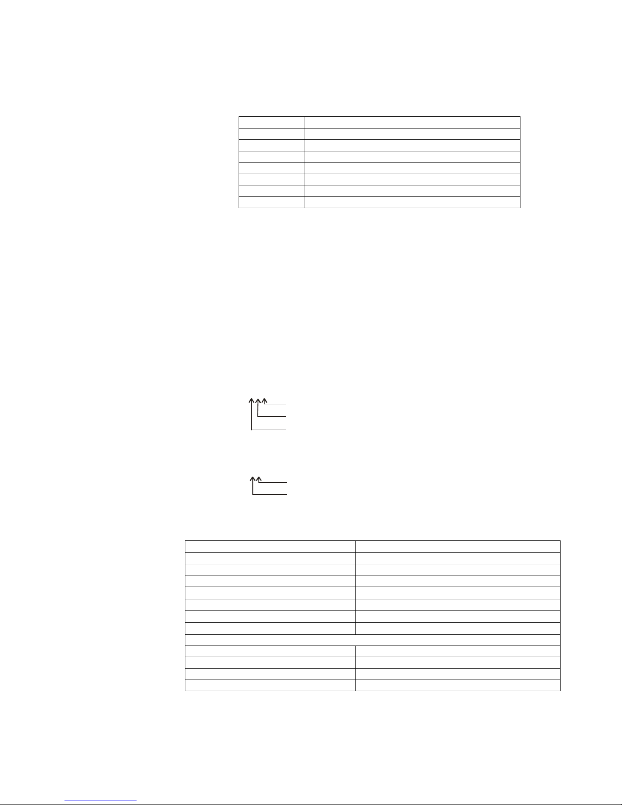
The programming status is indicated by the Green and Yellow LEDs and is explained
in the table below:
Normal ModeYellow Flashing
Press * to terminate Program ModeYellow Steady
Program mode waiting for a commandYellow Steady
Press # - terminates Add PIN commandYellow Steady + Green Flash
Repeat as many times as required
Enter # - blank PIN is enteredYellow Steady + Double Green Flash
Enter next PIN address # - e.g. 24#
Yellow Steady + Green Flash
Enter # - blank PIN is enteredYellow Steady + Double Green Flash
Enter address # - e.g. 23#
Yellow Steady + Green Flash
1code (inhibit) # - e.g. 11#
Yellow Steady
Program mode waiting for a commandYellow Steady
Enter MASTER codeYellow Flashing
Explanation / ActionLED Status
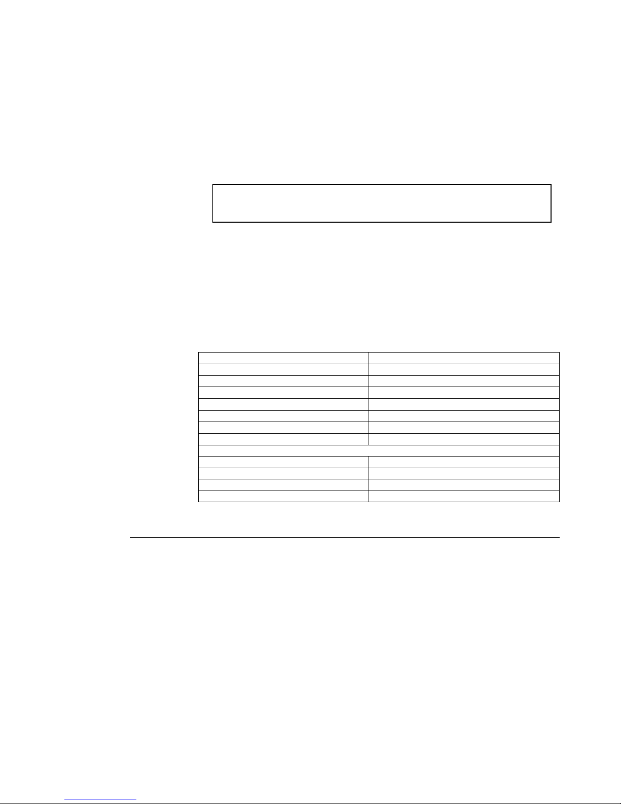
Command - Set Expiry (180-20 & 180-40 Only)
Each PIN record can be set for limited access either by limiting the number of
accesses allowed or by an expiry date. Access is suspended when the count limit is
reached or the date is passed. The PIN record is not deleted and can be reinstated by
setting a new count value or expiry date.
The Expiry command structure is:
2 # Address # Mode # Value #
where the parameters are: Address - address of the PIN to set
Mode - set count or date expiry mode
Value - expiry count value or date
180-Series Keypad Handbook rev 2.1 page 6 of 23