Assembly Instructions
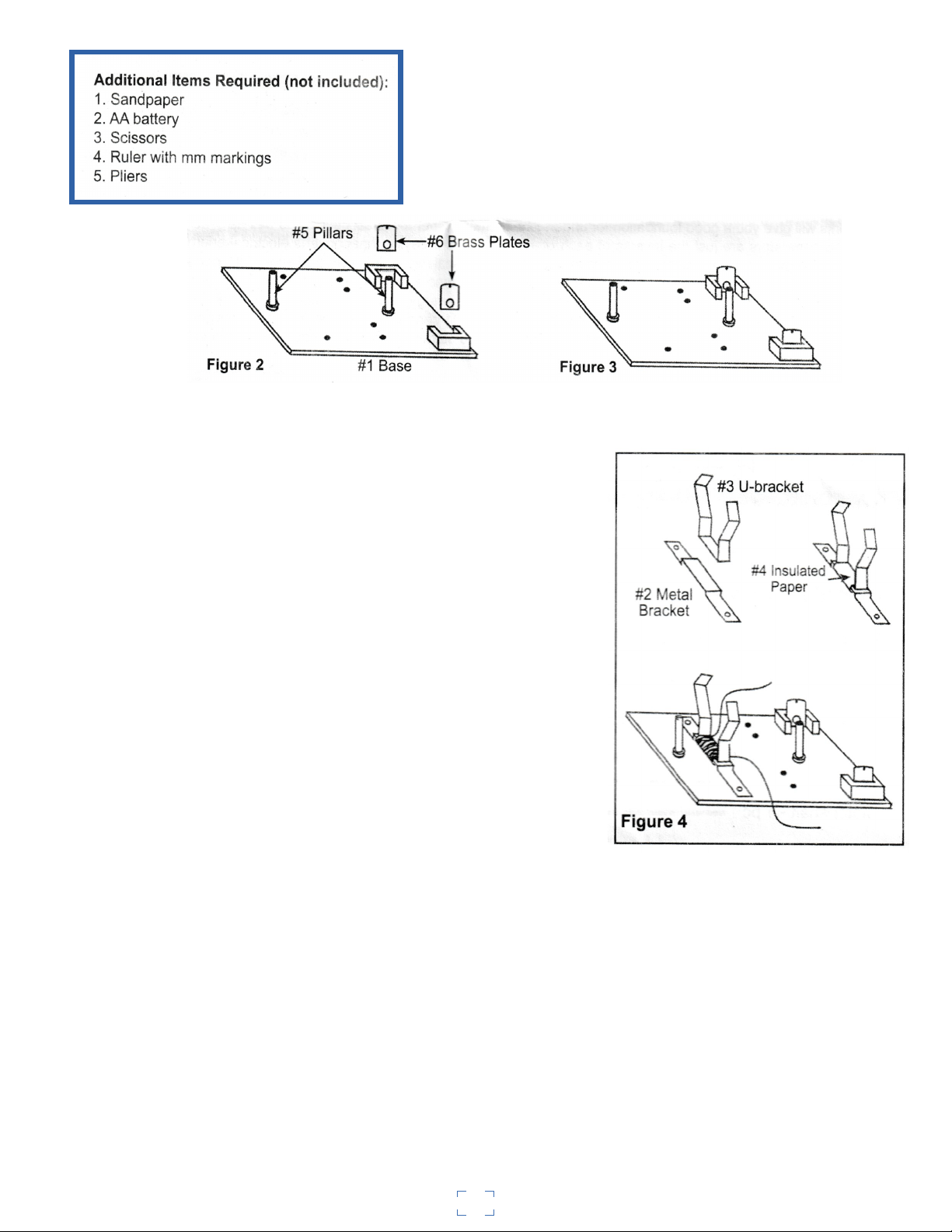
1. Insert brass plates (#6) into base slots marked number 1
and number 2 (as shown in Fig. 1). These will be the
connection plates for your battery. The hole in the brass
plates should be on the top and extending above the slots.
These holes are for the connection of wire.
2. Insert the two posts (#5) in the holes of the base marked number 3 and number 4 (see Fig. 1) as
shown in Figures 2 and 3. These posts will hold the armature shaft.
3. Attach the "U" shaped bracket (#3) to the metal bracket
(#2) by first wrapping the smaller piece of insulation paper
(#4) around both brackets with the glossy side down. If the
paper is too wide, trim to fit the "U" shaped bracket. Wrap the
paper all the way around both brackets so as to bind them
together (see Fig. 4). Leaving about 4cm of wire, start
wrapping one of the coils of magnet wire around both
brackets. When you get close to the end of the roll, stop when
you have about 8cm left. Place the bracket on the base, lining
up the holes marked number 5 and number 6 (see Fig. 1) on
the base and as in the illustration. Place screws into the holes
and thread on the hex nuts from the underside of the base.
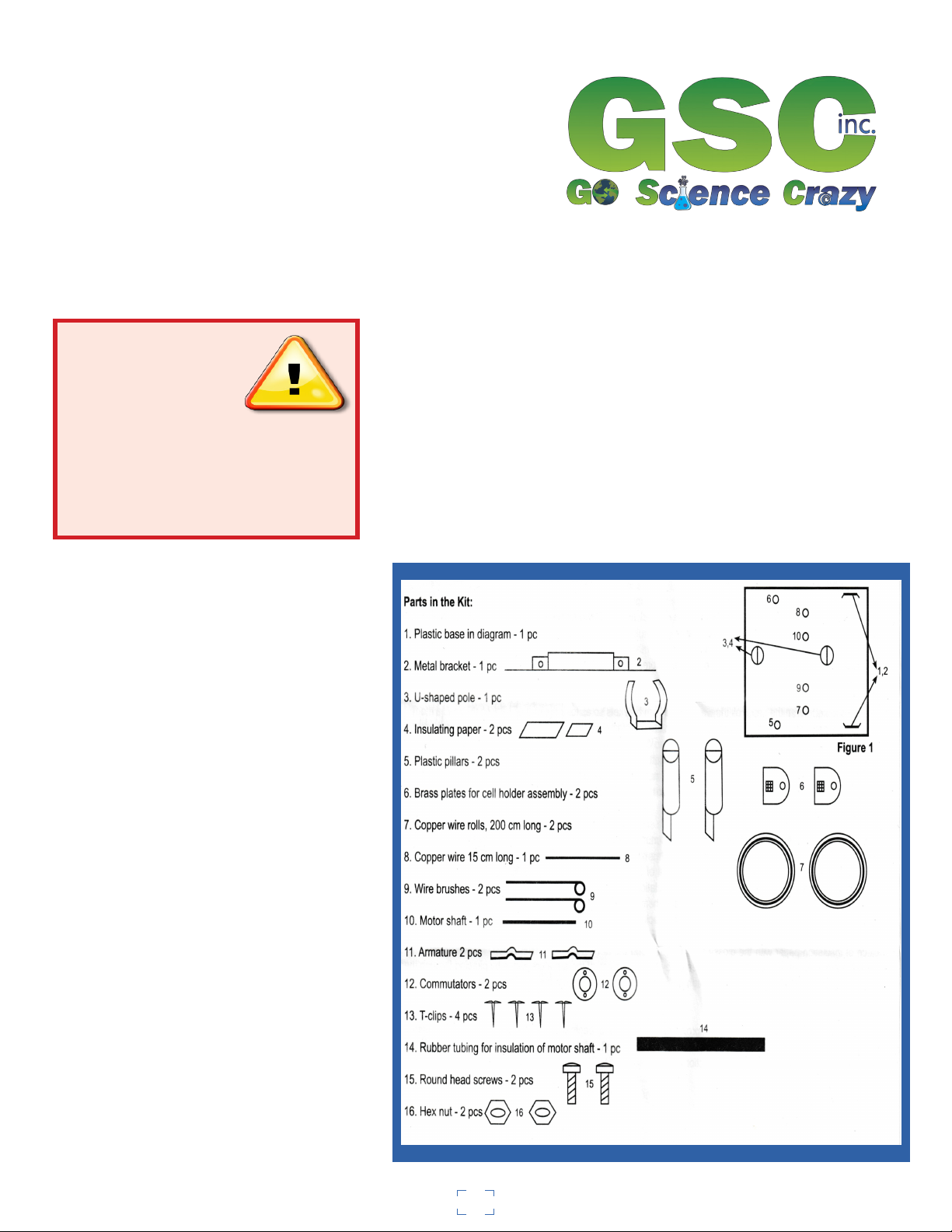
4.You will now construct the armature and the commutator.
Refer to the Part List (Fig. 1). You will need both armature
plates (#11), motor shaft (#10), bigger piece of insulating paper
(4), one coil of copper wire (#7), both commutators
(#12), and a plastic sleeve for insulation of motor shaft (#14).
Take the two armature plates (#11) and place them together in
such a way that the protrusions (bumps in the center) are facing
outward, which causes a hole to be formed for the motor shaft.
(See Fig. 5). Wrap the big piece of insulation paper with the
glossy side down around the armature. Pu8sh the armature shaft
through the hole created by the two halves of the armature
plates by piercing through the insulated paper. Push the motor
shaft through until it is approximately 1.5cm from the front
edge of the armature plates.
Take a second coil of wire and leaving
approximately 4cm of wire, begin
wrapping the wire around the armature.
Try to keep the number of wraps even
on both sides of the shaft. as you get
close to the end of the coil, leave
approximately 4cm of wire to make
connections later (see Fig. 5)
2