GSE 350 User manual

AWT35-500349 Issue AA June 2009
Model 350/355
Digital Weight Indicator
User Instructions

AWT35-500349 Issue AA June 2009
© Avery Weigh-Tronix group of companies 2009. All rights reserved.
No part of this publication may be reproduced, stored in an electronic retrieval system, or transmitted in any
form or by any means, electronic, mechanical, photocopying, recording or otherwise without the prior written
consent of the copyright owner, or as permitted by law or under license. Full acknowledgment of the source
must be given. Avery Weigh-Tronix is a registered trade mark of the Avery Weigh-Tronix group of
companies. This publication was correct at the time of going to print however; Avery Weigh-Tronix reserves
the right to alter without notice the specification, design, price or conditions of supply of any product or
service at any time.
All third party brands and product names used within this document are trademarks or registered trademarks
of their respective holders.

AWT35‐500349|June2009 Page1
Table of Contents
1.0INSTALLATION................................................................................................................................................3
1.1DESKTOPMOUNTING................................................................................................................................................3
1.2PANELMOUNTING(350DIECASTONLY).....................................................................................................................3
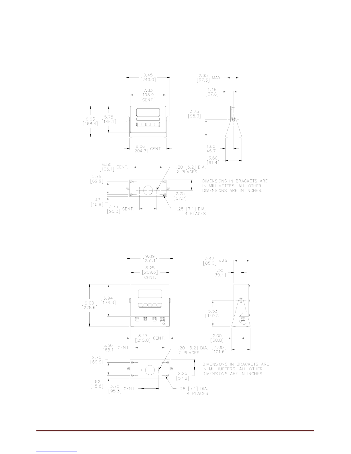
1.3OUTLINEDRAWINGS..................................................................................................................................................4
1.3.1350DieCast................................................................................................................................................4
1.3.2350StainlessSteel......................................................................................................................................4
1.3.3355StainlessSteel......................................................................................................................................5
1.4ACANDDCPOWER..................................................................................................................................................5
1.4.1BatteryOperated........................................................................................................................................5
1.4.2ACOperated................................................................................................................................................5
2.0KEYPADANDDISPLAY.....................................................................................................................................6
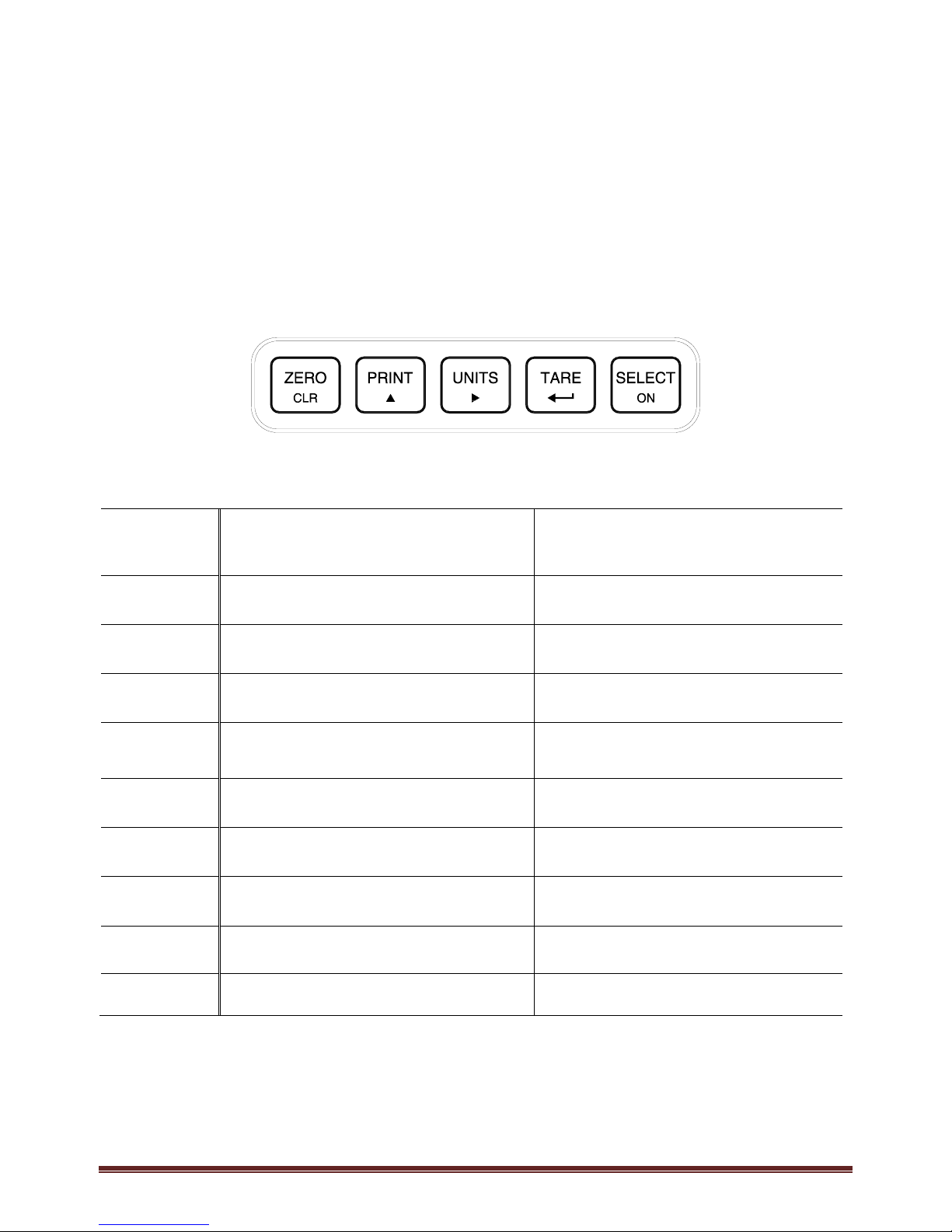
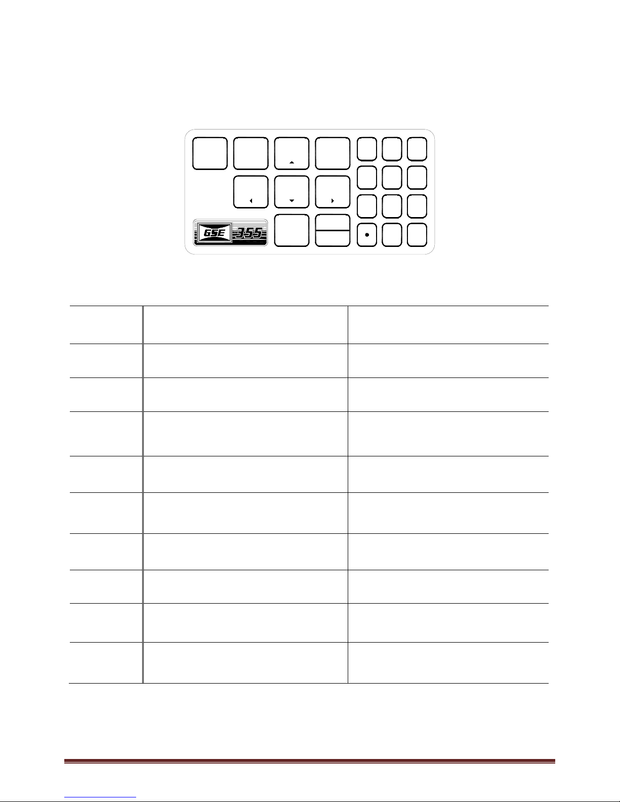
2.1KEYPADS.................................................................................................................................................................6
2.1.1Model350Keypad......................................................................................................................................6
2.1.2Model355Keypad......................................................................................................................................7
2.1.3WeighModeFunctions...............................................................................................................................8
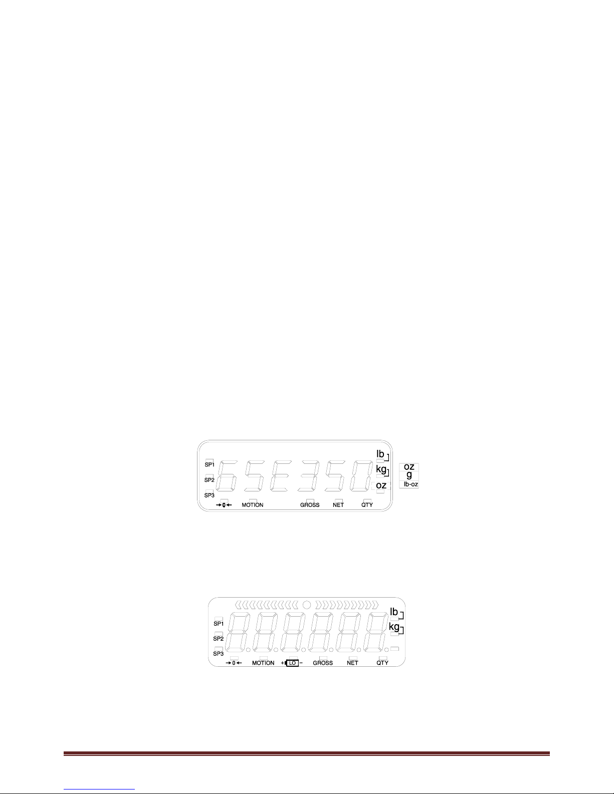
2.2DISPLAYS.................................................................................................................................................................8
2.2.1LED..............................................................................................................................................................8
2.2.2LCD..............................................................................................................................................................8
2.3REMOTEDISPLAY......................................................................................................................................................9
3.0OPERATION..................................................................................................................................................10
3.1ENTERINGATAREVALUE(MODEL350)......................................................................................................................10
3.2ENTERINGATAREVALUE(MODEL355)......................................................................................................................10
3.3ENTERANIDNUMBER.............................................................................................................................................10
3.4SETTIME&DATE...................................................................................................................................................11
3.4.1Model350.................................................................................................................................................11
3.4.2Model355.................................................................................................................................................11
3.5PARTSCOUNTING...................................................................................................................................................12
3.5.1Model350.................................................................................................................................................12
3.5.2Model355.................................................................................................................................................13
3.5.3Viewtheaveragepieceweight.................................................................................................................13
3.6PERCENTAGECHECKWEIGH.......................................................................................................................................14
3.6.1EnteraTargetValue.................................................................................................................................14
3.6.2StartCheckweighing.................................................................................................................................15
3.7FILL......................................................................................................................................................................15
3.7.1EnteraTargetValue.................................................................................................................................15
3.7.2StartFill.....................................................................................................................................................16
3.7.3FillExample...............................................................................................................................................16
3.8BATCH..................................................................................................................................................................17
3.8.1EnteraTarget...........................................................................................................................................17
3.8.2StartBatch................................................................................................................................................18
3.8.3BatchExample..........................................................................................................................................18
3.9DISCHARGE............................................................................................................................................................19
3.9.1EnteraTarget...........................................................................................................................................19
3.9.2Pre‐acts.....................................................................................................................................................20
3.9.3StartDischarge.........................................................................................................................................20

AWT35‐500349|June2009 Page2
3.9.4DischargeExample...................................................................................................................................20
3.10FILLANDDISCHARGE...........................................................................................................................................21
3.10.1EnteraTarget......................................................................................................................................21
3.10.2Pre‐acts................................................................................................................................................21
3.10.3ActivationMethod...............................................................................................................................22
3.10.4Pause....................................................................................................................................................22
3.10.5FillandDischargeExample..................................................................................................................22
3.11ABSOLUTECHECKWEIGH......................................................................................................................................23
3.11.1EnteraTargetValue............................................................................................................................23
3.11.2StartCheckweighing............................................................................................................................23
3.11.3AbsoluteCheckweighingExample.......................................................................................................24
3.12TARGETDEVIATIONCHECKWEIGH..........................................................................................................................24
3.12.1EnteraTargetValue............................................................................................................................24
3.12.2StartCheckweighing............................................................................................................................25
3.12.3TargetDeviationCheckweighingExample...........................................................................................25
3.13BATCH2...........................................................................................................................................................26
3.13.1EnteraTarget......................................................................................................................................26
3.13.2ActivationMethod...............................................................................................................................26
3.13.3Batch2Example...................................................................................................................................27
4.0TROUBLESHOOTING......................................................................................................................................28
4.1OPERATIONALERRORS.............................................................................................................................................28
4.2MISCELLANEOUSERRORS..........................................................................................................................................28
4.3HARDWAREERRORS................................................................................................................................................29
4.4COMMUNICATIONERRORS........................................................................................................................................29
5.0SPECIFICATIONS............................................................................................................................................30

AWT35‐500349|June2009 Page3
1.0 Installation
The standard Model 350 zinc die cast enclosure is a NEMA1 (IP 20) equivalent. The Model 350/355
stainless steel enclosure meets NEMA 4X/IP65 type specifications.
WARNING: Risk of electrical shock! Service of the indicator should
only be performed by authorized service personnel.
If the Model 350/355 is being plugged into an outlet, it must have an
earth ground. Make sure the supply voltage from the outlet meets the
requirements of the indicator.
When choosing a mounting location for the Model 350 die cast, ensure
that the unit is not installed in a wash-down area or conductive dust
environment.
1.1 Desktop Mounting
The die cast enclosure is designed for desktop mounting. When set on a flat surface, the front face is angled
for easy viewing. An optional swivel bracket is available for a broader range of viewing. All wiring enters
from the rear and can be secured with the included screw mounted cable ties.
The stainless steel models have a swivel bracket for quick adjustment of viewing angle.
1.2 Panel Mounting (350 Die Cast Only)
The optional panel mount kit allows the zinc die cast enclosure to be installed in a user panel. Allow for 2.00"
(57.2mm) depth behind the panel surface. See the Panel Mount cutout drawing below for dimensions.
7.33” – 7.45”
(
186.2 – 189.2mm
)
5.25” – 5.37”
(
133.4 – 136.4mm
)
PANEL
CUTOUT

AWT35‐500349|June2009 Page4
1.3 Outline Drawings
1.3.1 350 Die Cast
Figure 1: Model 350 Die Cast Dimensions
1.3.2 350 Stainless Steel
Figure 2: Model 350 Stainless Steel Dimensions

AWT35‐500349|June2009 Page5
1.3.3 355 Stainless Steel
Figure 3: Model 355 Stainless Steel Dimensions
1.4 AC and DC Power
1.4.1 Battery Operated
The optional battery module gives the Model 350/355 portability, providing a Model 350 with a LCD display
and one loadcell 20 hours minimum battery life, or a Model 350/355 with a LED display and one loadcell 8
hours minimum battery life.
1.4.1.1 ON/OFF Switch
The on/off switch for the Model 350 die cast is a rocker-type switch that is located on the rear of the
enclosure.
The on/off switch for the Model 350/355 stainless is a toggle-type (washdown type) switch replaces one of
the available strain reliefs on the bottom or rear of the enclosure.
The Model 350/355 will immediately switch to battery operation when AC power is interrupted if the switch is
in the ON position. Placing the switch in the OFF position prevents the battery from running down when AC
power is removed. The battery will be charged whenever there is AC power to the Model 350/355, regardless
of the switch position.
1.4.2 AC Operated
The AC version does not have an On/Off switch. Plug the indicator into an appropriate AC outlet. Unplug
the indicator to turn it off.

AWT35‐500349|June2009 Page6
2.0 Keypad and Display
2.1 Keypads
2.1.1 Model 350 Keypad
The Model 350 offers a sealed 5-button elastomer keypad which is used for operator input. Each key is
assigned two distinct functions. Various key combinations are also used. Each key has secondary functions;
allowing an operator to enter target values, perform piece samples, access setup parameters, etc.
Figure 4: Model 350 Keypad
Key Press Weigh Mode Count Mode
Performs a gross zero function and/or clears an entry
in progress. Hold this key on power-up to turn on
the display if in sleep mode.
Performs a quantity zero function and/or clears an
entry in progress.
Performs a print function and/or ‘scrolls’ through
digits during setpoint entry. Performs a print function and/or ‘scrolls’ through
digits during setpoint entry.
2Toggles between ‘lb’ and ‘kg’ and/or advances
cursor to next entry position. Toggles through standard sample sizes and/or
begins a new sample entry.
1Performs an auto-tare function (if enabled) and/or
accepts an entry in progress. Performs an auto-tare function and requests a piece
sample and/or accepts an entry in progress.
Toggles between display modes and/or restores
power to the indicator (if auto-shutoff enabled). Toggles between display modes and/or restores
power to the indicator (if auto-shutoff enabled).
+ 1Absolute clear – clears an entry in progress and/or
clears the value of a parameter. No function.
+ Backspace – erases the right-most digit during data
entry. Backspace – erases the right-most digit during
sample entry.
+ Extended gross. Extended gross.
2+ 1Turn off indicator by holding key for approximately
1 second. Battery mode only. Turn off indicator by holding key for
approximately 1 second. Battery mode only.
+ 2Reverse character scroll during data entry. Reverse character scroll during sample entry.

AWT35‐500349|June2009 Page7
2.1.2 Model 355 Keypad
The Model 355 keypad performs different functions in the Weigh Mode and the Count Mode. The numeric
keys make entering values such as tare or average piece weight easier.
123
CLR
NO
PRINT
STOP
START
TARGET
TARE
ZERO
ENTER
YES 0
SAMPLE
UNITS
SELECT
78
45
9
6
Figure 5: Model 355 Keypad
Key Press Weigh Mode Count Mode
"Performs a gross zero function and/or clears an entry
in progress. Performs a quantity zero function and/or clears an
entry in progress.
Performs a print function and/or ‘scrolls’ through
digits during setpoint entry. Performs a print function and/or ‘scrolls’ through
digits during setpoint entry.
2Toggles between ‘lb’ and ‘kg’ and/or advances
cursor to next entry position. Toggles through standard sample sizes and/or
begins a new sample entry.
#Performs an auto-tare function (if enabled) and/or
accepts an entry in progress. If the tare weight is
known, key in the value and press #.
Performs an auto-tare function and/or accepts an
entry in progress.
!Toggles between display modes and/or restores
power to the indicator (if auto-shutoff enabled).
Toggles between display modes and/or restores
power to the indicator (if auto-shutoff enabled).
(Performs a sample. If a number is keyed in before
hand, it will be used as the sample size. Accepts an
entry.
Performs a sample. If a number is keyed in before
hand, it will be used as the sample size.
Clears an entry in progress. Hold this key on
power-up to turn on the display if in sleep mode. Performs a quantity zero function and/or clears an
entry in progress.
&If setpoints are enabled, causes a process to start or
resume. If setpoints are enabled, causes a process to start or
resume.
%If setpoints are enabled, causes a pause. Press %
again to abort the process. If setpoints are enabled, causes a pause. Press %
again to abort the process.
$Wake up the indicator if in sleep mode. Turn on the
indicator if power is off. Access the target entry
mode.
Wake up the indicator if in sleep mode. Turn on the
indicator if power is off. Access the target entry
mode.

AWT35‐500349|June2009 Page8
2.1.3 Weigh Mode Functions
The Model 350 and Model 355 keypads have five primary Weigh Mode functions:
"Performs a gross zero and selects the gross mode
Initiates data transmission out the communication port
2Toggles the units of measure between lb, kg, (g, lb oz, oz if enabled)
#Tares any displayed weight and selects the net mode
!Toggles the display between GROSS, NET, QUANTITY and setpoint TARGETS (if enabled)
2.2 Displays
The Model 350 is available with a LED or LCD while the Model 355 is only available with a LED. The Model
350 and Model 355 will display alphanumeric data, but due to the nature of 7-segment LEDs/LCD and the
limitation of six digits, some information is abbreviated.
All segments and annunciators are illuminated for a brief display test upon power up. The current gross
weight is then displayed in default units.
2.2.1 LED
The LED display is a six digit, 7-segment bright green LED screen with 12 annunciators to show
weight and status information. The SP1, SP2, and SP3 annunciators are red, green, and yellow. Also
there is an annunciator for a third unit under kg. Place the third unit label above the third annunciator
(the third unit is available on both the LED and LCD displays).
Figure 6: Model 350/355 LED
2.2.2 LCD
The LCD display is a six digit, 7-segment black LCD screen with 12 annunciators and a bargraph to show the
operational status.
Figure 7: Model 350 LCD

AWT35‐500349|June2009 Page9
2.3 Remote Display
The remote display function allows a master indicator (Model 350 or Model 355) to be echoed to another
indicator (350 Series or 60 Series) and be used in a remote location. There are certain parameters that must
be set in order to have the master and slave indicators communicate together. If the remote display mode is
enabled, r-dsp will be shown on the display. Contact your GSE distributor for more information.

AWT35‐500349|June2009 Page10
3.0 Operation
The Model 350 and 355 can operate in a variety of modes such as check-weighing, parts counting and filling
etc. The functions described in this section are not available until enabled within the setup parameters.
Contact your GSE distributor to configure the indicator for a specific operation.
3.1 Entering a Tare Value (Model 350)
If a tare value is known, it is possible to enter that value into the tare register if the setup parameter has been
enabled.
1. From the gross or net mode press the !key until tare is displayed.
2. Use the key to scroll in the first number.
3. Press the 2key to move to the next digit.
4. Repeat steps 2 and 3 until the desired number is showing on the display.
5. Press the #key to accept the entered tare value.
3.2 Entering a Tare Value (Model 355)
If a tare value is known, it is possible to enter that value into the tare register if the setup parameter has been
enabled.
1. Enter the known tare value with the numeric keys and press #. The display will access the net mode.
3.3 Enter an ID Number
If the ID parameter has been enabled previously, a number may be entered to print on a ticket. Follow the
instructions below to enter an ID number.
1. Press the key from the weigh mode. The display will show the current ID number if one has been
entered previously.
2. Key in the desire ID number (numeric and/or alphanumeric) and press 1(Model 350) or ((Model
355). This will print a ticket.
-or-
3. If the ID number shown is acceptable simply press 1(Model 350) or ((Model 355). This will print a
ticket which includes the entered ID number.

AWT35‐500349|June2009 Page11
3.4 Set Time & Date
The time and date feature is stored as non-volatile (time/date setting will not be lost when the unit power is
reset).
The time and date can be accessed from the weigh mode with the !key if the time/date parameter has
been enabled. Time and date can be accessed via the communication port by sending 11%s.
3.4.1 Model 350
To enter the date from the Enter~date~01.01.70 prompt
EXAMPLE: 01.09.09 (January 9, 2009)
1. Press
to toggle through the numbers to enter the month.
2. Press
2twice to move the decimal point over to separate the month from the day. It is not necessary to
enter a 0 before a single digit month. If it is a double-digit entry, press 2once to move the cursor and
then to scroll through the digits.
3. Press
to toggle through the numbers to enter the day.
4. Press
2twice to move the decimal point over to separate the day from the year. It is not necessary to
enter a 0 before a single digit month. If it is a double-digit entry, press 2once to move the cursor and
then to scroll through the digits.
5. Press
to toggle through the numbers to enter the year.
6. Press
2once to move the cursor and then press to scroll through the digits.
7. Press
1twice to accept the entry.
To enter the time from the Enter~tine~00.00.00 prompt
EXAMPLE: 16.32.41 (4:32:41 P.M.)
1. Press
to toggle through the numbers to enter the hour. Hours must be entered as military time.
2. Press
2once to move the cursor. Press to select the next digit.
3. Press
2twice to move the decimal point over to separate the hour from the minutes. It is not necessary
to enter a 0 before a single digit hour.
3.4.2 Model 355
To enter the date from the Enter~date~01.01.70 prompt
EXAMPLE: 01.09.09 (January 9, 2009)
1. Key in the date in the following format: 1.9.9. It is not necessary to enter a 0 before a single digit month.
2. Press
(to except the date and move to the time entry. Press (again to bypass the time entry.
To enter the time from the Enter~tine~00.00.00 prompt
EXAMPLE: 16.32.41 (4:32:41 P.M.)
1. Key in the date in the following format: 16.32.41
2. Press
(to except the time and move to the weigh mode.

AWT35‐500349|June2009 Page12
3.5 Parts Counting
The counting parameter must be enabled before using. Follow the instructions below for sampling and
counting parts. A new sample must be performed for each unique part being counted. The indicator will not
store the average piece weight.
3.5.1 Model 350
3.5.1.1 Sample selectable fixed counts from the weigh mode
1. From the weigh mode, press !until the QTY annunciator is lit. The display may show do APS if
an average piece weight is not found. This message is to let you know this is a new sample. Go
to step 2.
2. Press
#to perform a sample. Add 10 will be displayed. If 10 is the desired sample size, go to
step 4. Otherwise go to step 3.
3. If a fixed sample size other than 10 is desired, press !to toggle through sample size choices 5,
10, 20, 50 and 100. When the desired sample size is displayed, go to step 4.
4. Add the pieces to be sampled and press #.After motion is stabilized, the sampled quantity will
be displayed.
5. Continue adding parts to be counted. The display will show the number of parts added.
6. If a different part needs to be counted, go to step 2.
3.5.1.2 To sample using variable counts
1. From the weigh mode, press !until the QTY annunciator is lit. The display may show do APS if
an average piece weight is not found. This message is to let you know this is a new sample. Go
to step 2.
2. Press
#to perform a sample. Add 10 will be displayed.
3. Add pieces and key in the number of pieces being sampled by entering the known sample size. First
press the key until the first digit is displayed. Use the 2key to move to the next digit. Continue
using the and 2keys until the desired sample size is displayed and press #.
4. Add the pieces to be sampled and press #.After motion is stabilized, the sampled quantity will be
displayed.
5. Continue adding parts to be counted. The display will show the number of parts added.
6. If a different part needs to be counted, go to step 2.
3.5.1.3 View the average piece weight
1. From the QTY mode, press !once. The display will show APS and then flash the last sampled
average piece weight. This value cannot be altered.
2. Press the
!key to exit the average piece weigh mode. Continue to press !until the desire
weigh mode parameter is displayed.

AWT35‐500349|June2009 Page13
3.5.2 Model 355
3.5.2.1 To sample using selectable fixed counts from the weigh mode
1. From the weigh mode press (. Add 10 will be displayed. If 10 is the desired sample size, go to
step 3. Otherwise go to step 2.
2. If a fixed sample size other than 10 is desired, press !or 2to toggle through sample size
choices 5, 10, 20, 50 and 100. When the desired sample size is displayed, go to step 3.
3. Add the pieces to be sampled and press (.After motion is stabilized, the sampled quantity will
be displayed.
4. Continue adding parts to be counted. The display will show the number of parts added.
5. If a different part needs to be counted, go to step 2.
3.5.2.2 To sample using variable counts
1. From the weigh mode press (. Add 10 will be displayed. If 10 is the desired sample size, go to step
3. Otherwise go to step 2.
2. Add pieces and key in the number of pieces being sampled with the numeric keys. Press (to accept
the entry.
3. Add the pieces to be sampled and press (.After motion is stabilized, the sampled quantity will be
displayed.
4. Continue adding parts to be counted. The display will show the number of parts added.
5. If a different part needs to be counted, go to step 2.
3.5.3 View the average piece weight
1. From the QTY mode, press !once. The display will show APS and then flash the last sampled
average piece weight. This value cannot be altered.
2. Press the !key to exit the average piece weigh mode. Continue to press !until the desire weigh
mode parameter is displayed.

AWT35‐500349|June2009 Page14
3.6 Percentage Checkweigh
This feature is commonly used in checkweigh applications and must be enabled before attempting to use.
After a target weight is entered, upper and lower tolerances are entered as a percentage of the target. Over
and under tolerance values are automatically calculated according to the percentages entered. The desired
target may be based on gross weight, net weight or quantity (if counting is enabled).
3.6.1 Enter a Target Value
3.6.1.1 Model 350
1. Press !until tArG1 is displayed. If the target value shown is correct, press 1to go to the PctLo
value. To change the target value, go to step 2.
2. Press
until the first digit of the new target is displayed. Press 2to accept the number displayed.
Continue this step until the desired number is entered. Refer to the example below as a reference.
Example: Target of 20
Press four times
DISPLAY READS X2
Press 2to accept the 2 that is displayed
DISPLAY READS X2 .
Press once
DISPLAY READS X20
Press 1to accept the target weight as 20
DISPLAY READS X20
3. Press
1to accept the entered value. Once the tare key is pressed, PctLo will be displayed. This is
where the low percentage will be entered. Enter target percentage value in the same manner as the
target weight was entered above. If the displayed value is correct, press 1.
4. Next the PctHi value will be displayed. This is target percentage value for the high percentage. Enter this
value in the same manner as the target weight was entered above. If the displayed value is correct press
!. The display will return to the weigh mode. Press !to view the desired weigh mode parameter.
3.6.1.2 Model 355
1. Press !until tArG1 is displayed.
2. Key in the target weight with the numeric keys and press (.
3. The PctLo value will be displayed. Key the in target percentage value with the numeric keys and press
(.
4. The PctHi value will be displayed. Key the in target percentage value with the numeric keys and press
(.
5. Press
!to select the desired weigh mode parameter.

AWT35‐500349|June2009 Page15
3.6.2 Start Checkweighing
The checkweigh applications do not have a start function. Simply put the item to be weighed onto the scale
platter. An annunciator will illuminate to indicate whether the item is within tolerance.
3.6.2.1 Annunciators
In order for the annunciators to activate, the displayed value must be at least five graduations above zero.
Status Annunciator Status Annunciator Color
(LED)
OVER SP 1 Illuminated Red
GOOD SP 2 Illuminated Green
UNDER SP 3 Illuminated Yellow
3.7 Fill
The fill program is used for single-speed or dual-speed filling operations. The dual-speed fill operation allows
for both a fast and a slow fill mode. During a fast-fill, setpoints 1 (SP1) and 2 (SP2) are activated. During a
slow-fill or single-speed fill, only setpoint 1 (SP1) is activated. This feature must be enabled before
attempting to use. Over filling can be prevented with the use of pre-act values (PA1 and PA2). Pre-act 1
(PA1) is used for switching the fast fill to a slow fill. Pre-act 2 (PA2) is used as a final cutoff value.
3.7.1 Enter a Target Value
Pressing 1or (alone allows access to the subsets. PA1 and PA2 are the subsets for Targ 1.
3.7.1.1 Model 350
1. Press !until tArG1 is displayed.
2. Press
until the first digit of the new target is displayed. Press 2to accept the number displayed.
Continue this step until the desired number is entered. Refer to the example below.
Example: Target of 20
Press four times
DISPLAY READS X2
Press 2to accept the 2 that is displayed
DISPLAY READS X2 .
Press once
DISPLAY READS X20
Press 1to accept the target weight as 20
DISPLAY READS X20
3. Press
1. Once the tare key is pressed, it is possible that PA1 will be displayed if the pre-act parameter
is enabled.
If a value is desired, enter it in the same manner as the target weight was entered above. When the
displayed value is correct, press 1.

AWT35‐500349|June2009 Page16
If no value is to be entered or PA1 is not displayed, press 1to go to the next screen.
4. If PA2 is displayed, enter the value in the same manner as the target weight was entered above and
press 1to accept or press 1to return to the weigh mode. Press !to view the desired weigh mode
parameter.
3.7.1.2 Model 355
1. Press !until tArG1 is displayed.
2. Key in the desired target value with the numeric keys and press (.
3. The PA1 value will be displayed. Key the in value with the numeric keys and press (.
4. The PA2 value will be displayed. Key the in value with the numeric keys and press (.
5. Press
!to select the desired weigh mode parameter.
3.7.2 Start Fill
3.7.2.1 Activation Method
The fill begins with the selected activation method. The method is determined by the parameters in the setup
mode.
The deactivation of the setpoints is automatic. The desired target may be based on net or quantity (if
counting is enabled).
Activation types
•Tare key – Press the #key to start the process. A tare weight will be set and the weight will switch
to net zero.
•Remote key – Press the remote key switch.
•Auto-start – The process is automatically activated. It waits for a no-motion condition and then adds
the target to the current displayed weight to achieve a relative cutoff value.
3.7.2.2 Annunciators
Fill Status Annunciator Status
Fast Fill SP 1 & SP 2 Illuminated
Dribble Fill (or Single-Speed Fill) SP 1 Illuminated
Fill Done or Pause SP 1 & SP 2 Off
3.7.3 Fill Example
With a system set up to fill 55-gallon drums with motor oil, the following settings might be used to achieve an
accurate final fill weight of 400 lbs.:
Parameter Setting Actual Cutoff Value Comments
Targ 1 = 400 Desired final weight.
Pre-act 1 = 28 400 – 28 = 372.0 Switch to dribble feed at 372.
Pre-act 2 = .5 400 – 0.5 = 399.5 Final fill valve closes at 399.5.

AWT35‐500349|June2009 Page17
3.8 Batch
The standard batch program is used for batching up to three separate items. Ingredients 1 through 3 use
setpoints and pre-acts 1 through 3 respectively. Ingredients are batched one at a time. Free falling product
can be accounted for with the use of pre-act values (PA1 – PA3). This feature must be enabled before
attempting to use.
3.8.1 Enter a Target
Pressing 1or (alone allows access to the subsets. PA 1 and PA 2 are the subsets for Targ 1.
3.8.1.1 Model 350
1. Press !until tArG1 is displayed.
2. Press
until the first digit of the new target is displayed. Press 2to accept the number displayed.
Continue this step until the desired number is entered.
Example: Target of 20
Press four times
DISPLAY READS X2
Press 2to accept the 2 that is displayed
DISPLAY READS X2 .
Press once
DISPLAY READS X20
Press 1to accept the target weight as 20
DISPLAY READS X20
3. Press
1. Once the tare key is pressed, it is possible that PA1 will be displayed if the pre-act parameter
is enabled.
If a value is desired, enter it in the same manner as the target weight was entered above. When the
displayed value is correct, press 1.
If no value is to be entered or PA1 is not displayed, press 1to go to the next screen.
4. Repeat steps 2 and 3 until all targets and pre-acts are entered. Press 1to return to the weigh mode.
3.8.1.2 Model 355
1. Press !until tArG1 is displayed.
2. Key in the desired target value with the numeric keys and press (.
3. The PA1 value will be displayed. Key the in value with the numeric keys and press (.
4. Repeat steps 2 and 3 for tArG2, PA2, tArG3 and PA3.
5. Press
!to select the desired weigh mode parameter.

AWT35‐500349|June2009 Page18
3.8.2 Start Batch
3.8.2.1 Activation Method
The batch begins with the selected activation method. The method is determined by the parameters in the
setup mode. The deactivation of the setpoints is automatic. The desired target may be based on net or
quantity (if counting is enabled).
Activation types
•Tare key – Press the #key to start the process. A tare weight will be set and the weight will switch
to net zero.
•Remote key – Press the remote key switch.
•Auto-start – The process is automatically activated. It waits for a no-motion condition and then adds
the target to the current displayed weight to achieve a relative cutoff value.
3.8.2.2 Annunciators
Batch Status Annunciator Status Setpoint Status (Requires Setpoint Option Board)
Fill 1 SP 1 Illuminated Relay 1 Contacts Closed,
Relay 2 and 3 Contacts Open
Fill 2 SP 2 Illuminated Relay 2 Contacts Closed,
Relay 1 and3 Contacts Open
Fill 3 SP 3 Illuminated Relay 3 Contacts Closed,
Relay 1 and 2 Contacts Open
3.8.3 Batch Example
With a system set up a system to make a 50,000 lb batch with water (30,000 lbs.), corn syrup (15,000 lbs.)
and caramel color (5,000 lbs.), ingredient 1 should start with 1and subsequent ingredients should auto-
start.
Parameter Setting Actual Cutoff Value Comments
Target 1 = 30,000 Desired water weight.
Pre-Act 1 = 100 30,000 – 100 = 29,900 Water valve closes at 29,900 lbs. Free-fall will bring
weight to 30,000.
Start 1 = Tare Start water with #.
Target 2 = 15,000 Desired corn syrup weight.
Pre-Act 2 = 236 15,000 – 236 = 14,764 Corn syrup valve closes at 14,764 lbs. Free-fall will
bring weight to 15,000.
Start 2 = Auto Calculated cutoff value for
corn syrup is added to
current displayed weight
Start corn syrup when water is done and motion has
stopped.
Target 3 = 5,000 Desired caramel coloring weight.
Pre-Act 3 = 142 5,000 – 142 = 4,858 Carmel coloring valve closes at 4,858. Free-fall will
bring weight to 5,000.
Start 3 = Auto Calculated cutoff value for
caramel coloring is added
to current displayed weight
Start caramel coloring when corn syrup is done and
motion has ceased.
Other manuals for 350
2
This manual suits for next models
1
Table of contents
Other GSE Touch Panel manuals
Popular Touch Panel manuals by other brands

Duomo
Duomo KS23 Trio Labstart manual

3M
3M MicroTouch Near Field Imaging (NFI) Integration guide

Crestron
Crestron Isys TPS-4L Operations & installation guide

MAXHUB
MAXHUB Classic Series user manual

Portwell
Portwell FUDA2-S1 21 Series user manual

IEI Technology
IEI Technology IOVU-751R-CE5/UX-R10 user manual