GSI Group X Series Sweep User manual

PNEG-1858
12" and 16" “X” Series Sweep
Operator’s Manual
PNEG-1858
Date: 11-27-12

2PNEG-1858 12" and 16" “X” Series Sweep
Model Number of My Sweep:
__________________________________
Date Delivered:
__________________________________
Date Installed:
__________________________________
NOTE: The manufacturer reserves the right to improve its product whenever possible and practical to
do so. We reserve the right to change, improve and modify products at any time without
obligation to make changes, improvements and modifications on equipment sold previously.
Personnel operating or working around this equipment should read this manual. This manual
must be delivered with equipment to its owner. Failure to read this manual and its safety
instructions is a misuse of the equipment. Any misuse of the equipment may void the warranty.

Table of Contents
PNEG-1858 12" and 16" “X” Series Sweep 3
Contents
Chapter 1 Safety .....................................................................................................................................................4
Safety Guidelines .................................................................................................................................. 4
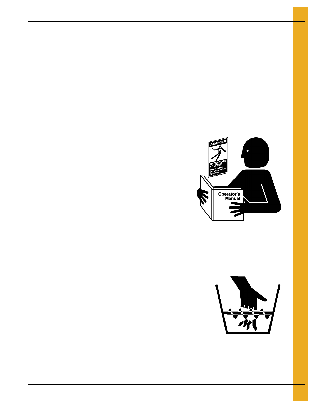
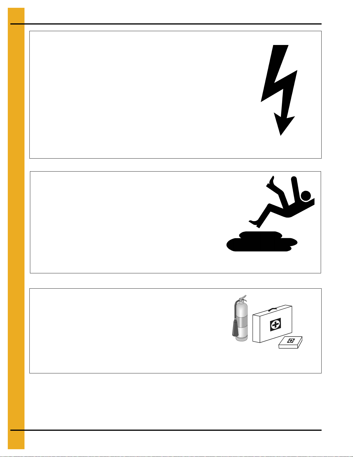
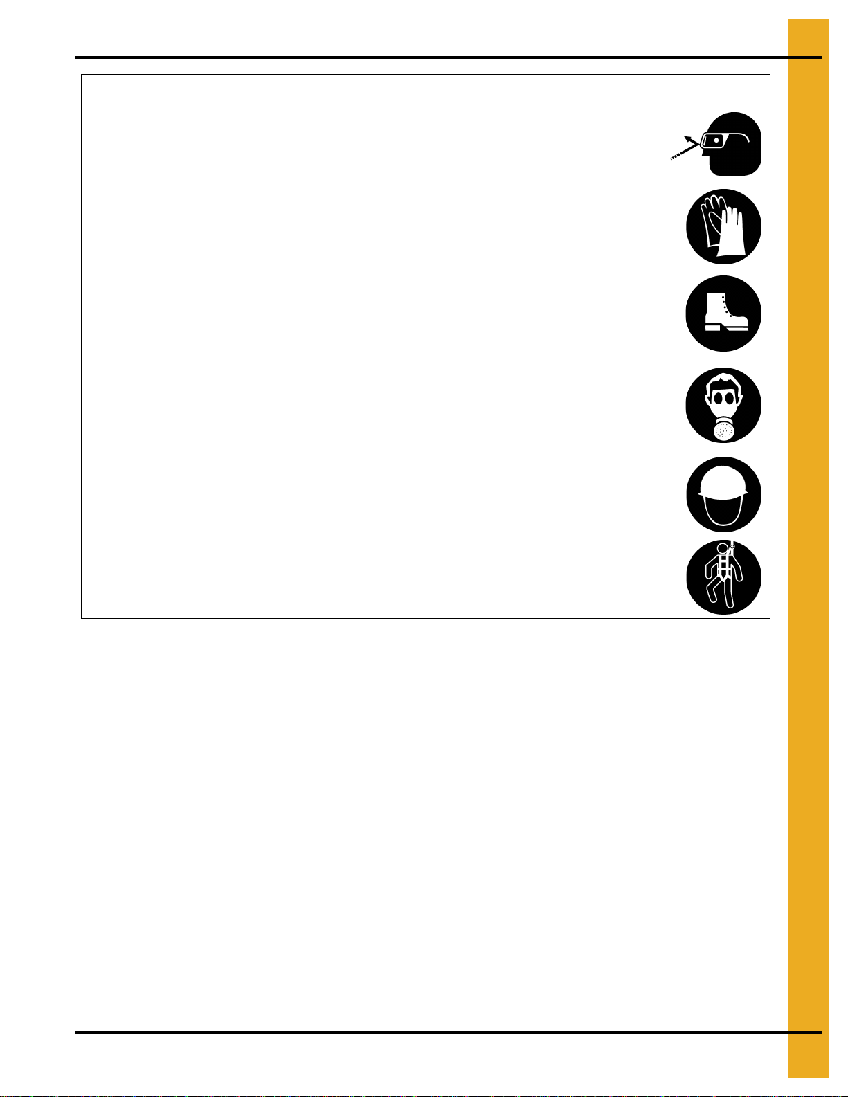
Safety Instructions ................................................................................................................................. 5
Operator Qualifications ......................................................................................................................... 9
Chapter 2 Safety Decals ......................................................................................................................................10
Chapter 3 Product Overview ...............................................................................................................................14
Sweep Criteria Recommendations ...................................................................................................... 14
Product Information ............................................................................................................................. 16
General Information ............................................................................................................................ 16
Capacities and Specifications ............................................................................................................. 18
Chapter 4 Start-Up ...............................................................................................................................................21
Perform Pre-Start Checks ................................................................................................................... 21
Start the Auger .................................................................................................................................... 21
Chapter 5 Operation ............................................................................................................................................22
Operating the Sweep Auger ................................................................................................................ 22
Operating in Manual Mode .................................................................................................................. 23
Operating in Auto Mode ...................................................................................................................... 27
Cleanout Mode .................................................................................................................................... 29
Warning Messages ............................................................................................................................. 31
Chapter 6 Shut Down ...........................................................................................................................................32
Normal Shut Down .............................................................................................................................. 32
Emergency Shut Down ....................................................................................................................... 32
Storage Preparation ............................................................................................................................ 32
Chapter 7 Maintenance ........................................................................................................................................33
Maintain the Auger .............................................................................................................................. 33
Lubrication ........................................................................................................................................... 34
Chapter 8 Control Panel Diagrams .....................................................................................................................39
Control Panel Schematic 380V and 480V ........................................................................................... 39
Control Panel Schematic 600V ........................................................................................................... 40
Chapter 9 Troubleshooting .................................................................................................................................41
FAQs ................................................................................................................................................... 42
Chapter 10 Parts List ...........................................................................................................................................49
Main Auger Components ................................................................................................................... 50
Auger Drive Components .................................................................................................................. 54
Track Drive Components ................................................................................................................... 56
Flight Components ............................................................................................................................ 58
Wheel and Caster Components ........................................................................................................ 62
12" and 16'' Plow Components .......................................................................................................... 64
Center Pivot and Collector Ring Components (Prior to 2013) ........................................................... 66
Center Pivot and Collector Ring Components (Current) ................................................................... 68
Electrical Connection Components ................................................................................................... 70
Control Panel Components ............................................................................................................... 71
Control Panel Assembly - 380V 3 Phase .......................................................................................... 72
Control Panel Assembly - 480V 3 Phase .......................................................................................... 74
Control Panel Assembly - 600V 3 Phase .......................................................................................... 76
Components ...................................................................................................................................... 78
Chapter 11 Warranty ............................................................................................................................................79

4PNEG-1858 12" and 16" “X” Series Sweep
1. Safety
Safety Guidelines
This manual contains information that is important for you, the owner/operator, to know and understand.
This information relates to protecting personal safety and preventing equipment problems. It is the
responsibility of the owner/operator to inform anyone operating or working in the area of this equipment
of these safety guidelines. To help you recognize this information, we use the symbols that are defined
below. Please read the manual and pay attention to these sections. Failure to read this manual and its
safety instructions is a misuse of the equipment and may lead to serious injury or death.
DANGER
WARNING
CAUTION
NOTICE
This is the safety alert symbol. It is used to alert you
to potential personal injury hazards. Obey all safety
messages that follow this symbol to avoid possible
injury or death.
WARNING indicates a hazardous situation which, if not
avoided, could result in death or serious injury.
CAUTION, used with the safety alert symbol, indicates a
hazardous situation which, if not avoided, could result in
minor or moderate injury.
NOTICE is used to address practices not related to
personal injury.
DANGER indicates a hazardous situation which, if not
avoided, will result in death or serious injury.

1. Safety
PNEG-1858 12" and 16" “X” Series Sweep 5
Safety Instructions
Our foremost concern is your safety and the safety of others associated with this equipment. We want to
keep you as a customer. This manual is to help you understand safe operating procedures and some
problems that may be encountered by the operator and other personnel.
As owner and/or operator, it is your responsibility to know what requirements, hazards, and precautions
exist, and to inform all personnel associated with the equipment or in the area. Safety precautions may be
required from the personnel. Avoid any alterations to the equipment. Such alterations may produce a very
dangerous situation, where SERIOUS INJURY or DEATH may occur.
This equipment shall be installed in accordance with the current installation codes and applicable
regulations, which should be carefully followed in all cases. Authorities having jurisdiction should be
consulted before installations are made.
Follow Safety Instructions
Carefully read all safety messages in this manual and
safety signs on your machine. Keep signs in good
condition. Replace missing or damaged safety signs. Be
sure new equipment components and repair parts include
the current safety signs. Replacement safety signs are
available from the manufacturer.
Learn how to operate the machine and how to use controls
properly. Do not let anyone operate without instruction.
Keep your machinery in proper working condition.
Unauthorized modifications to the machine may impair
the function and/or safety and affect machine life.
If you do not understand any part of this manual or need
assistance, contact your dealer.
Read and Understand Manual
Keep Hands Away from Moving Parts
DO NOT put hand or arm in hopper. Rotating auger can
crush and dismember.
DO NOT put any kind of tool inside hopper to try and clear
debris while the auger is running. Damage to the equipment
will result.
ALWAYS turn off and lock out all power sources before
servicing equipment.
Keep all shields and covers in place during operation. Rotating Auger

1. Safety
6PNEG-1858 12" and 16" “X” Series Sweep
Operate Motor Properly
In an emergency, shut down the power source.
Turn OFF and lock out all power sources before performing
any maintenance.
Do not operate electric motor equipped units until motors are
properly grounded.
Disconnect power on electrical driven units before resetting
motor overloads.
Do not repetitively stop and start the drive in order to free a
plugged condition. Jogging the drive in this manner can damage
the equipment and/or drive components. Electric Shock Hazard
Practice Safe Maintenance
Understand service procedures before doing work. Keep area
clean and dry.
Never lubricate, service, or adjust machine while it is in operation.
Keep hands, feet, and clothing away from rotating parts.
Keep all parts in good condition and properly installed. Fix
damage immediately. Replace worn or broken parts. Remove any
built-up grease, oil, and debris. Maintain Equipment
and Work Area
Prepare for Emergencies
Be prepared if fire starts.
Keep a first aid kit and fire extinguisher handy.
Keep emergency numbers for doctors, ambulance service,
hospital, and fire department near your telephone. Keep Emergency Equipment
Quickly Accessible

1. Safety
PNEG-1858 12" and 16" “X” Series Sweep 7
Wear Protective Clothing
Wear close-fitting clothing and safety equipment appropriate
to the job.
Remove all jewelry.
Tie long hair up and back.
Wear safety glasses at all times to protect eyes from debris.
Wear gloves to protect your hands from sharp edges on
plastic or steel parts.
Wear steel-toed boots to help protect your feet from falling
debris. Tuck in any loose or dangling shoestrings.
A respirator may be needed to prevent breathing potentially
toxic fumes and dust.
Wear a hard hat to help protect your head.
Wear appropriate fall protection equipment when working at
elevations greater than six feet (6').
Eye Protection
Gloves
Steel-Toed Boots
Respirator
Hard Hat
Fall Protection

1. Safety
8PNEG-1858 12" and 16" “X” Series Sweep
Operate Unload Equipment Properly
• Untrained operators subject themselves and others to SERIOUS INJURY
or DEATH. NEVER allow untrained personnel to operate this equipment.
• NEVER work alone.
• Keep children and other unqualified personnel out of the working
area at ALL times. Refer to the Start-Up section of this manual for
diagrams of the work area.
• Make sure ALL equipment is locked in position before operating.
• NEVER start equipment until ALL persons are clear of the work area.
• Keep hands and feet away from the auger intake and other moving parts.
• NEVER attempt to assist machinery operation or to remove trash from equipment while
in operation.
• Be sure all operators are adequately rested and prepared to perform all functions of operating
this equipment.
• NEVER allow any person intoxicated or under the influence of alcohol or drugs to operate
the equipment.
• Make sure someone is nearby who is aware of the proper shut down sequence in the event of an
accident or emergency.
• ALWAYS think before acting. NEVER act impulsively around the equipment.
• NEVER allow anyone inside a bin, truck or wagon which is being unloaded by an auger or
conveyor. Flowing grain can trap and suffocate in seconds.
• Use ample overhead lighting after sunset to light the work area.
• Keep area around intake free of obstacles such as electrical cords, blocks, etc., that might
trip workers.
• NEVER drive, stand or walk under the equipment.
• Use caution not to hit the auger when positioning the load.
• ALWAYS lock out ALL power to the equipment when finished unloading a bin.
• Be aware of pinch points. A pinch point is a narrow area between two surfaces that is likely to trap
or catch objects and so is a potential safety hazard.
Operate Unload
Equipment Safely

1. Safety
PNEG-1858 12" and 16" “X” Series Sweep 9
Operator Qualifications
A. The User/Operator must be competent and experienced to operate auger equipment. Anyone who
works with or around augers must have good common sense in order to be qualified. These persons
must also know and meet all other qualifications, such as:
i. Any person who has not read and/or does not understand all operation and safety procedures
is not qualified to operate any auger systems.
ii. Certain regulations apply to personnel operating power machinery. Personnelunder the age of
18 years may not operate power machinery, including augers. It is your responsibility, as owner
and/or supervisor, to know what these regulations are in your area or situation.
iii. Unqualified or incompetent persons are to remain out of the work area.
iv. O.S.H.A. (Occupational Safety and Health Administration) regulations state: “At the time of
initial assignment and at least annually thereafter, the employer shall instruct every employee
in the safe operation and servicing of all equipment with which the employee is, or will be
involved”. (Federal Occupational Safety and Health Standards for Agriculture. Sub Part D,
Section 1928.57 (a) (6)).
B. As a requirement of O.S.H.A., it is necessary for the employer to train the employee in the safe
operating and safety procedures for this auger. The sign-off sheet is for your convenience and
personal record keeping. All unqualified persons should always stay out of work area. It is strongly
recommended that another qualified person who knows the shut down procedure is in the area in
the event of an emergency.
Date Employee Name Supervisor Name

10 PNEG-1858 12" and 16" “X” Series Sweep
2. Safety Decals
The images below show the location of the decals and safety signs which should appear on the
“X” Series Sweep. (Refer to Page 10-13 for Decals.)
Figure 2A Safety Decal General Location Placement
NOTE: Please remember safety signs provide important safety information for people working near bin
unloading equipment that is in operation. Any safety signs that are worn, missing, illegible or
painted over should be replaced immediately. Obtain FREE replacements by contacting GSI.
Ref # Description Location
ARotating Auger Front of top flange
B High Voltage Corner of auger motor mount and each side of center well
CHigh Voltage Corner of drive motor plate
D Rotating Flighting Back of top flange
EShear Point Corner of drive motor plate
F Trip Hazard Each side of auger motor housing

2. Safety Decals
PNEG-1858 12" and 16" “X” Series Sweep 11
Figure 2B
Ref # Part # Description
ADC-1416 Safety Decal, Rotating Auger
B DC-1224 Safety Decal, High Voltage
CDC-889 Safety Decal, High Voltage
D DC-834 Safety Decal, Rotating Flighting
ROTATING AUGER!
•DISCONNECTANDLOCKOUTPOWERBEFORE
SERVICING, ADJUSTING OR CLEANING.
• KEEP HANDS, FEET, HAIR AND LOOSE
CLOTHING AWAY FROM ROTATING AUGER AND
MOVING PARTS AT ALL TIMES.
• NEVER REMOVE OR MODIFY GUARDS OR
SHIELDS.
FAILURE TO HEED WILL RESULT IN
SERIOUS INJURY OR DEATH!
DC-1416
DANGERDANGER
DC-889
DANGERDANGER
DC-1224
DANGER
DANGER
1. Keep all safety shields and devices in place.
2. Keep hands, feet, hair, loose clothing, and other objects away
from moving parts.
3. Do not operate the machine unless visitors, children, and all other
untrained personnel are well clear of the machine and work area.
4. Stop the machine and lock out power to clean, lubricate, service,
or adjust.
5. Read operation and assembly manual completely before using
equipment.
Failure to heed these warnings will
result in serious injury or death.
DC-834
Rotating flighting
can kill or dismember
.
DANGERDANGER
B
C
D
A

2. Safety Decals
12 PNEG-1858 12" and 16" “X” Series Sweep
Figure 2C
Ref # Part # Description
EDC-2192 Safety Decal, Shear Point
F DC-2190 Safety Decal, Trip Hazard
WARNING
DC-2192
SHEAR POINT
Keep feet clear
of sprocket.
Moving parts can cut
and crush.
CAUTION
DC-2190
TRIP HAZARD
Track mounted
to floor.
Use caution when
approaching sweep
to avoid tripping.
E
F

2. Safety Decals
PNEG-1858 12" and 16" “X” Series Sweep 13
A. DANGER Signs No. DC-1395, DC-2191 and DC-2193 were supplied with your bin unloading
equipment. The safety signs should be applied to the side of the bin near the bin opening, so they
can be viewed by people entering into the bin storage building. Do not cover any safety signs or any
other signs that are already there.
B. If the safety sign location suggested is not in full view because of equipment modifications, other
equipment in the area or any reason, then locate the safety sign in a more suitable location.
C. Be certain the surface is clean, dry and free of dirt and oil. Peel paper backing from decals and stick
into place. The adhesive backing will bond on contact.
NOTE: Please remember, safety signs provide important safety information for people working near bin
unloading equipment that is in operation.
If the Safety Sign cannot be easily read for any reason or has been painted over, replace it
immediately. Additional Safety Signs may be obtained free of charge from your dealer, distributor
or ordered from the factory.
Figure 2D
Ref # Part # Description
GDC-2191 Safety Decal, Trip Hazard
H DC-1395 Safety Decal, Rotating Flighting
IDC-2193 Safety Decal, Automatic Equipment
THISBINISEQUIPPEDWITH GRAIN AUGERS
WHICHCANKILLORDISMEMBER.
ROTATINGFLIGHTING!
KEEPCLEAROFALLAUGERSANDNEVERENTER
THISBINUNLESSALLPOWERIS
DISCONNECTEDANDLOCKEDOUT
.
FAILURETODO SO WILLRESULT IN
SERIOUSINJURYOR DEATH!
DC-1395
DANGER
DANGER
GSIGroup217-226-4421 DC-2193
ROTATINGAUGER
AUTOMATICEQUIPMENT
MAYSTARTATANYTIME
DANGER
Thisbinis equippedwithgrain
augerswhichcankill or dismember.
Keepclearofall augers and never
enterthisbin unless all power is
disconnectedandlockedout.
Failuretodoso will resultin
seriousinjuryor death!
CAUTION
GSIGroup217-226-4421 DC-2191
TRIPHAZARD
Trackmounted
tofloor.
Usecaution when
approachingsweep
toavoid tripping.
DC-2193
ROTATING AUGER
AUTOMATIC EQUIPMENT
MAY START AT ANY TIME
DANGER
This bin is equipped with grain
augers which can kill or dismember.
Keep clear of all augers and never
enter this bin unless all power is
disconnected and locked out.
Failure to do so will result in
serious injury or death!
THIS BIN IS EQUIPPED WITH GRAIN AUGERS
WHICH CAN KILL OR DISMEMBER.
ROTATING FLIGHTING!
KEEP CLEAR OF ALL AUGERS AND NEVER ENTER
THIS BIN UNLESS ALL POWER IS
DISCONNECTED AND LOCKED OUT.
FAILURE TO DO SO WILL RESULT IN
SERIOUS INJURY OR DEATH!
DC-1395
DANGERDANGER
I
HG
CAUTION
DC-2191
TRIP HAZARD
Track mounted
to floor.
Use caution when
approaching sweep
to avoid tripping.

14 PNEG-1858 12" and 16" “X” Series Sweep
3. Product Overview
Sweep Criteria Recommendations
Congratulations! Your selection of the GSI “X” Series Sweep is a wise investment. It will give you years of
dependable service. The main function of the “X” Series Sweep is to clean out the remaining grain, from
the bin, after all gravity unloading has finished. The GSI “X” Series Sweep is a single pass sweep only.
The unit will only operate in a round grain bin equipped with a center sump in the bin floor.
NOTE: The bin manufacturer should be contacted for their recommendations on the bin’s structural
integrity. The following are sweep criteria recommendations.
Issues Recommendations
Flooring
A track is required under each of the sweep wheels where they travel over the
aeration (steel) floor. The track should be a minimum of 10 gauge thick and made
from steel. The steel can be galvanized for the wheel paths. A Table on Page 17 is
included that shows radius dimensions locating the points of contact between the
sweep and the bin floor. The dimensions may be used to figure the material
quantities of track to support the sweep across the aeration flooring. The track
material is not supplied with the sweep and must be supplied by the installer.
The dimensions are approximate and the assembled sweep should be checked for
exact points of contact.
Center Sump Size
When installing a 12" or 16" sweep, the minimum recommended opening is 42" x 42".
The sump hopper supplied by GSI was designed with sufficient clearance around the
collector ring housing to allow grain to gravity flow through the hopper and be carried
away by the material handling equipment below. 42-3/4" is the maximum opening size
to allow rolling clearance for the casters assembled to the head end jack. If made
smaller, grain flow may be decreased to an unacceptable level.
Flow of grain is limited when using this sump and collector ring housing assembly.
The collector ring housing extends 23-1/2" down from the floor surface and is
approximately 14-1/4" x 14-1/4" in size.
Number of Intermediate Sumps
Intermediate sumps must be installed on a maximum of 10' centers where the sweep
will be parked during storage. The first intermediate sump should be placed at a
maximum of 10' from the center sumps and the end sump should be no more than 4'
from the bin wall.
The extra sumps will help clean out the grain in front of the sweep, reducing the
start-up load. Doing this will save labor dollars and hours of work to dig out the sweep
and will help the sweep during start-up. The sweep is not designed to start-up when
submerged in material. The sweep should be parked behind the intermediate sumps
with sumps on the auger side of the sweep.
Routing the Power Supply to
the Sweep
The only option is to use the hopper sump with collector ring. This allows the power
to be transferred through a mechanical device in the center sump and does not twist
any cords.
Floor Level Tolerance
The top edge of the sump hopper and the top edge of the “X” brace support must be
level with the floor. The floor must be level within 3/4" plus (or) minus, preferably less.
Any high or low points must be gradually sloped. The change in elevation should be
no more than 3/4" over 60".
Bin Roundness Tolerance
Diameter tolerances are limited by foundation limits and sweep operation as well as
structural issues. For 72' diameter and larger, the overall tolerance would be plus or
minus 1-1/4" on the radius, plus or minus 1" on 42'-66' diameter bins and plus or
minus 3/4" on 30'-39' bins.

3. Product Overview
PNEG-1858 12" and 16" “X” Series Sweep 15
Bin Opening Size
Required for Installation
The head section is the largest piece of a standard “X” Series Sweep. The
dimensions for a 16" head section are 23-1/2" x 55-1/4". If the bin wall is not too thick,
this unit should fit through a 23-1/2" x 47" opening. The dimensions for a 12" head
section are 21-1/4" x 51-1/2". Again, if the bin wall is not too thick, the section should
fit through an opening 21-1/2 x 45".
Voltage Specification
The “X” Series Sweep is designed to operate using 460 Volt 3 Phase 60 Hz,
380V 50 Hz or 600V 60 Hz. The voltage must be within plus or minus 4% for
proper operation.
Voltages outside of this range may cause excessive power draw or other operating
problems. Please contact the factory for applications outside of these parameters.
Electrical Requirements
Electrical controls and wiring should be installed by a qualified electrician. The motor
disconnect switches and conductor cables should comply with the National Electric
Code and any local codes which may apply.
A main power disconnect switch capable of being locked only in the OFF position
should be used. This is integrated into the control panel for the “X” Series Sweeps.
Disconnect and lock out the power before servicing the equipment, entering the bin
or resetting the motor overloads.
The control panel MUST be mounted OUTSIDE the bin near the door. It must be
located so the operator has a full view of the equipment and can see that all
personnel are clear. It must NEVER be installed inside the bin. Motor thermal
protection leads must also be wired into or plugged into the control panel before the
sweep will operate.
Issues Recommendations

3. Product Overview
16 PNEG-1858 12" and 16" “X” Series Sweep
Product Information
1. The “X” Series Sweep includes the following components:
Control Panel
Two (2) Motors
Motor Covers
Motor Mount
Auger Flighting
Auger Back Shield Assembly
Caster Wheels
Track
Shield Brush
2. The following components are NOT included with the “X” Series Sweep:
Track Anchors
Electrical Components
- Wire
- Fittings
- Conduit
3. The unit will operate only in a round grain bin equipped with a center sump in the bin floor.
General Information
1. GSI reserves the right to improve its product whenever possible and practical to do so. We reserve
the right to change, improve and modify products at any time without obligation to make changes,
improvements and modifications on equipment sold previously.
2. This new bin sweep auger has been engineered and manufactured to give years of dependable
service.Thecareandmaintenance ofthisequipmentwillaffectthesatisfactionandserviceobtained.
By following the instructions and recommendations, the owner should receive quality service for
many years. If additional information or assistance is required, please contact GSI.
This “X” Series Sweep is a single pass sweep. Consult the manufacturer of the
storage tank regarding the requirements or restrictions of the sweeping process.
The manufacturer may require a multiple pass sweep.
CAUTION
WARNING
NEVER enter a grain bin unless ALL power driven equipment has been shut down.
Disconnect and lock out power before entering the bin or servicing the equipment.

3. Product Overview
PNEG-1858 12" and 16" “X” Series Sweep 17
3. It is important to check both the quantity of parts and their descriptions with the packing list enclosed
within each package. All claims for freight damage or shortage must be made by the consignee
within ten (10) days of the date of the occurrence. The consignee should accept the shipment after
noting the damage or loss on the bill of lading.
4. Table below shows radius dimensions locating the points of contact between the sweep and the bin
floor. The dimensions may be used to figure material quantities of track to support the sweep across
the aeration flooring. The track material is not supplied with the sweep and must be supplied by the
installer. The dimensions are approximate and the assembled sweep should be checked for exact
points of contact.
Track and Support Wheel Radius Dimensions
Bin
Dia. # of
Sections Radius Dimensions for Support Wheels and Track from Center Pivot
(Support wheel locations are approximate and should be checked after sweep assembly is complete.)
27' 26' - 2-1/2" (1.89 m) 8' (2.44 m) Track 8'-10" (2.71 m)
30' 26' - 2-1/2" (1.89 m) 8' (2.44 m) Track 10'-10" (3.30 m)
33' 26' - 2-1/2" (1.89 m) 8' (2.44 m) Track 12'-10" (3.91 m)
34' 26' - 2-1/2" (1.89 m) 8' (2.44 m) Track 12'-10" (3.91 m)
36' 26' - 2-1/2" (1.89 m) 8' (2.44 m) Track 13'-10" (4.22 m)
37' 26' - 2-1/2" (1.89 m) 8' (2.44 m) Track 14'-10" (3.91 m)
39' 26' - 2-1/2" (1.89 m) 8' (2.44 m) Track 15'-10" (4.83 m)
40' 26' - 2-1/2" (1.89 m) 8' (2.44 m) Track 15'-10" (4.83 m)
42' 26' - 2-1/2" (1.89 m) 8' (2.44 m) Track 16'-10" (5.13 m)
43' 26' - 2-1/2" (1.89 m) 8' (2.44 m) Track 16'-10" (5.13 m)
45' 26' - 2-1/2" (1.89 m) 8' (2.44 m) Track 17'-10" (5.44 m)
48' 36' - 2-1/2" (1.89 m) 16' (4.88 m) 18' (5.49 m) Track 19'-10" (6.05 m)
49' 36' - 2-1/2" (1.89 m) 16' (4.88 m) 18' (5.49 m) Track 19'-10" (6.05 m)
51' 36' - 2-1/2" (1.89 m) 16' (4.88 m) 18' (5.49 m) Track 20'-10" (6.35 m)
54' 36' - 2-1/2" (1.89 m) 16' (4.88 m) 18' (5.49 m) Track 22'-10" (6.96 m)
55' 36' - 2-1/2" (1.89 m) 16' (4.88 m) 18' (5.49 m) Track 22'-10" (6.96 m)
57' 36' - 2-1/2" (1.89 m) 16' (4.88 m) 18' (5.49 m) Track 23'-10" (7.27 m)
59' 36' - 2-1/2" (1.89 m) 16' (4.88 m) 18' (5.49 m) Track 24'-10" (7.57 m)
60' 36' - 2-1/2" (1.89 m) 16' (4.88 m) 18' (5.49 m) Track 25'-10" (7.88 m)
62' 36' - 2-1/2" (1.89 m) 16' (4.88 m) 18' (5.49 m) Track 26'-10" (8.18 m)
63' 36' - 2-1/2" (1.89 m) 16' (4.88 m) 18' (5.49 m) Track 26'-10" (8.18 m)
66' 46' - 2-1/2" (1.89 m) 16' (4.88 m) 18' (5.49 m) Track 27'-10" (8.49 m)
68' 46' - 2-1/2" (1.89 m) 16' (4.88 m) 18' (5.49 m) Track 29'-10" (9.10 m)
69' 46' - 2-1/2" (1.89 m) 16' (4.88 m) 18' (5.49 m) Track 29'-10" (9.10 m)
72' 46' - 2-1/2" (1.89 m) 16' (4.88 m) 26' (7.93 m) 28' (8.54 m) Track 31'-10" (9.71 m)
75' 46' - 2-1/2" (1.89 m) 16' (4.88 m) 26' (7.93 m) 28' (8.54 m) Track 32'-10" (10.01 m)
78' 46' - 2-1/2" (1.89 m) 16' (4.88 m) 26' (7.93 m) 28' (8.54 m) Track 33'-10" (10.32 m)
80' 46' - 2-1/2" (1.89 m) 16' (4.88 m) 26' (7.93 m) 28' (8.54 m) Track 34'-10" (10.62 m)
81' 46' - 2-1/2" (1.89 m) 16' (4.88 m) 26' (7.93 m) 28' (8.54 m) Track 34'-10" (10.62 m)
84' 46' - 2-1/2" (1.89 m) 16' (4.88 m) 26' (7.93 m) 28' (8.54 m) Track 36'-10" (11.23 m)
87' 56' - 2-1/2" (1.89 m) 16' (4.88 m) 26' (7.93 m) 28' (8.54 m) Track 36'-10" (11.23 m)
88' 56' - 2-1/2" (1.89 m) 16' (4.88 m) 26' (7.93 m) 28' (8.54 m) Track 36' (10.98 m) 39'-10" (12.14 m)
90' 56' - 2-1/2" (1.89 m) 16' (4.88 m) 26' (7.93 m) 36' (10.98 m) 38' (11.59 m) Track 40'-10" (12.45 m)
91' 56' - 2-1/2" (1.89 m) 16' (4.88 m) 26' (7.93 m) 36' (10.98 m) 38' (11.59 m) Track 40'-10" (12.45 m)
92' 56' - 2-1/2" (1.89 m) 16' (4.88 m) 26' (7.93 m) 36' (10.98 m) 38' (11.59 m) Track 41'-10" (12.75 m)
95' 56' - 2-1/2" (1.89 m) 16' (4.88 m) 26' (7.93 m) 36' (10.98 m) 38' (11.59 m) Track 42'-10" (13.06 m)
98' 56' - 2-1/2" (1.89 m) 16' (4.88 m) 26' (7.93 m) 36' (10.98 m) 38' (11.59 m) Track 44'-10" (13.67 m)
99' 56' - 2-1/2" (1.89 m) 16' (4.88 m) 26' (7.93 m) 36' (10.98 m) 38' (11.59 m) Track 44'-10" (13.67 m)
105' 56' - 2-1/2" (1.89 m) 16' (4.88 m) 26' (7.93 m) 36' (10.98 m) 38' (11.59 m) Track 47'-10" (14.58 m)
113' 66' - 2-1/2" (1.89 m) 16' (4.88 m) 26' (7.93 m) 36' (10.98 m) 38' (11.59 m) Track 46' (14.02 m) 51'-10" (15.80 m)
115' 66' - 2-1/2" (1.89 m) 16' (4.88 m) 26' (7.93 m) 36' (10.98 m) 38' (11.59 m) Track 46' (14.02 m) 52'-10" (16.11 m)
118' 66' - 2-1/2" (1.89 m) 16' (4.88 m) 26' (7.93 m) 36' (10.98 m) 38' (11.59 m) Track 46' (14.02 m) 53'-10" (16.41 m)
120' 66' - 2-1/2" (1.89 m) 16' (4.88 m) 26' (7.93 m) 36' (10.98 m) 46' (14.02 m) 48' (14.63 m) Track 55'-10" (17.02 m)
131' 76' - 2-1/2" (1.89 m) 16' (4.88 m) 26' (7.93 m) 36' (10.98 m) 46' (14.02 m) 48' (14.63 m) Track 56' (17.07 m) 60'-10" (18.55 m)
132' 76' - 2-1/2" (1.89 m) 16' (4.88 m) 26' (7.93 m) 36' (10.98 m) 46' (14.02 m) 48' (14.63 m) Track 56' (17.07 m) 61'-10" (18.85 m)
135' 76' - 2-1/2" (1.89 m) 16' (4.88 m) 26' (7.93 m) 36' (10.98 m) 46' (14.02 m) 48' (14.63 m) Track 56' (17.07 m) 62'-10" (19.16 m)
139' 76' - 2-1/2" (1.89 m) 16' (4.88 m) 26' (7.93 m) 36' (10.98 m) 46' (14.02 m) 48' (14.63 m) Track 56' (17.07 m) 64'-10" (19.77 m)
156' 86' - 2-1/2" (1.89 m) 16' (4.88 m) 26' (7.93 m) 36' (10.98 m) 46' (14.02 m) 48' (14.63 m) Track 56' (17.07 m) 66' (20.12 m) 73'-10" (25.10 m)

3. Product Overview
18 PNEG-1858 12" and 16" “X” Series Sweep
Capacities and Specifications
1. Use below Table to determine the horsepower required.
NOTE: Sweep is not designed to start under full load.
Horsepower Requirements and Shield Lengths
Bin
Diameter Track Drive
Horsepower
Bushel/MT per Hour Horsepower Back Shield
Length Pivot to
End
Plow Length
Pivot to End
Minimum
Plow Length Pivot to
End Maximum
12" - 3000 (77.5) 12" - 5000 (125)
to 7000 (180) 16" - 8000 (205)
to 10000 (255)
27' 1/2 15 15 15 12'-4" (3.78 m) 13' - 4-1/8" (4.09 m) 14'-1" (4.32 m)
30' 1/2 15 15 15 13'-4" (4.09 m) 14' - 2-3/4" (4.37 m) 14' - 11-3/4" (4.57 m)
33' 1/2 15 15 15 15'-4" (4.68 m) 16' - 4-3/8" (4.98 m) 16' - 11-7/8" (5.18 m)
34' 1/2 15 15 15 15'-4" (4.68 m) 16' - 4-3/8" (4.98 m) 16' - 11-7/8" (5.18 m)
36' 1/2 15 15 15 16'-4" (4.98 m) 17' - 4-3/8" (5.29 m) 17' - 11-7/8" (5.49 m)
37' 1/2 15 15 15 17'-4" (5.29 m) 18' - 2-7/8" (5.57 m) 18' - 11-7/8" (5.79 m)
39' 1/2 15 15 15 18'-4" (5.59 m) 19'-3" (5.87 m) 20'-0" (6.10 m)
40' 1/2 15 15 15 18'-4" (5.59 m) 19'-3" (5.87 m) 20'-0" (6.10 m)
42' 1/2 15 15 15 19'-4" (5.90 m) 20'-3" (6.18 m) 21'-0" (6.40 m)
43' 1/2 15 15 15 19'-4" (5.90 m) 20'-3" (6.18 m) 21'-0" (6.40 m)
45' 1/2 15 15 15 20'-4" (6.20 m) 21' - 2-7/8" (6.48 m) 22'-0" (6.72 m)
48' 1/2 15 15 15 22'-4" (6.81 m) 23' - 4-1/8" (7.12 m) 24'-1" (7.34 m)
49' 1/2 15 15 15 22'-4" (6.81 m) 23' - 4-1/8" (7.12 m) 24'-1" (7.34 m)
51' 1/2 15 15 15 23'-4" (7.12 m) 24' - 2-3/4" (7.37 m) 24' - 11-3/4" (7.60 m)
54' 1/2 15 15 15 25'-4" (7.73 m) 26' - 4-3/8" (8.04 m) 26' - 11-7/8" (8.23 m)
55' 1/2 15 15 15 25'-4" (7.73 m) 26' - 4-3/8" (8.04 m) 26' - 11-7/8" (8.23 m)
57' 1/2 15 15 15 26'-4" (8.03 m) 27' - 4- 3/8" (8.33 m) 27' - 11-7/8" (8.51 m)
59' 1/2 15 15 20 27'-4" (8.34 m) 28' - 2-7/8" (8.59 m) 28' - 11-7/8" (8.82 m)
60' 1/2 15 15 20 28'-4" (8.64 m) 29'-3" (8.92 m) 30'-0" (9.15 m)
62' 1/2 15 15 20 29'-4" (8.95 m) 30'-3" (9.22 m) 31'-0" (9.45 m)
63' 1/2 15 15 20 29'-4" (8.95 m) 30'-3" (9.22 m) 31'-0" (9.45 m)
66' 1/2 15 15 20 31'-4" (9.56 m) 32' - 2-7/8" (9.81 m) 33'-0" (10.06 m)
68' 1/2 15 15 20 32'-4" (9.86 m) 33' - 4-1/8" (10.16 m) 34'-1" (10.39 m)
69' 1/2 15 15 20 32'-4" (9.86 m) 33' - 4-1/8" (10.16 m) 34'-1" (10.39 m)
72' 1/2 15 15 20 34'-4" (10.47 m) 35'-3" (10.75 m) 36'-0" (10.98 m)
75' 1/2 15 15 20 35'-4" (10.78 m) 36' - 4-3/8" (11.09 m) 36' - 11-7/8" (11.28 m)
78' 1/2 15 15 20 37'-4" (11.39 m) 38' - 2-7/8" (11.64 m) 38' - 11-7/8" (11.86 m)
80' 1/2 15 20 20 38'-4" (11.69 m) 39'-3" (11.97 m) 40'-0" (12.20 m)
81' 1/2 15 20 20 38'-4" (11.69 m) 39'-3" (11.97 m) 40'-0" (12.20 m)
84' 1/2 15 20 25 40'-4" (12.30 m) 41' - 2-7/8" (12.55 m) 42'-0" (12.80 m)
87' 1/2 15 20 25 40'-4" (12.30 m) 41' - 2-7/8" (12.55 m) 42'-0" (12.80 m)
88' 1/2 15 20 25 42'-4" (12.91 m) 43' - 4-1/8" (13.19 m) 44'-1" (13.44 m)
90' 1/2 15 20 25 43'-4" (13.22 m) 44' - 2-3/4" (13.47 m) 44' - 11-3/4" (13.69 m)
91' 1/2 15 20 25 43'-4" (13.22 m) 44' - 2-3/4" (13.47 m) 44' - 11-3/4" (13.69 m)
92' 1/2 15 20 25 44'-4" (13.52 m) 45'-3" (13.80 m) 46'-0" (14.02 m)
95' 1/2 15 20 25 45'-4" (13.83 m) 46' - 4-3/8" (14.13 m) 46' - 11-7/8" (14.30 m)
98' 1/2 15 20 25 47'-4" (14.44 m) 48' - 2-7/8" (14.68 m) 48' - 11-7/8" (14.91 m)
99' 1/2 15 20 25 47'-4" (14.44 m) 48' - 2-7/8" (14.68 m) 48' - 11-7/8" (14.91 m)
105' 1/2 15 25 30 50'-4" (15.35 m) 51' - 2-7/8" (15.60 m) 52'-0" (15.85 m)
113' 1/2 15 25 30 50'-4" (15.35 m) 55'-3" (16.84 m) 56'-0" (17.07 m)
115' 1/2 15 25 30 55'-4" (16.86 m) 56' - 4-3/8" (17.16 m) 56' - 11-7/8" (17.38 m)
118' 1/2 15 25 30 57'-4" (17.49 m) 58' - 2-7/8" (17.73 m) 58' - 11-7/8" (17.96 m)
120' 1/2 15 25 30 58'-4" (17.79 m) 59'-3" (18.06 m) 60'-0" (18.29 m)
131' 1/2 15 25 30 63'-4" (19.31 m) 64' - 2-3/4" (19.56 m) 64' - 11-3/4" (19.79 m)
132' 1/2 15 25 30 64'-4" (19.62 m) 65'-3" (19.89 m) 66'-0" (20.12 m)
135' 1/2 15 25 30 65'-4" (19.92 m) 66' - 4-3/8" (20.23 m) 66' - 11-7/8" (20.42 m)
139' 1/2 15 25 30 67'-4" (20.53 m) 68'-2" 7/8" (20.81 m) 68'-11 7/8" (21.04 m)
156' 1/2 15 25 40 76'-4" (23.27 m) 77' - 4-3/8" (20.23 m) 77' - 11-7/8" (20.42 m)
Due to continual improvements, GSI designs and specifications are subject to change without notice.
WARNING
Electrical controls and wiring should be installed by a qualified electrician. The
motor disconnect switches and conductor cables should comply with the National
Electrical Code and any local codes.

3. Product Overview
PNEG-1858 12" and 16" “X” Series Sweep 19
NOTE: The horsepower recommendations are for augering reasonably dry grain. High moisture grain
(greater than 15%) will require greater power for maximum capacity.
NOTE: Sweep carrier wheels require plates or track over aeration flooring for travel. Carrier wheel track
is not supplied with the sweep unit. Contact your installer or flooring provider for possible sources
and details.
2. The motor starting controls must be located outside the bin. They must NEVER be installed on the
“X” Series Sweep auger inside the bin.
3. Disconnect and lock out the power before resetting motor overloads.
4. Disconnect and lock out the power before entering the bin.
5. Disconnect and lock out the power before servicing the equipment.
6. Position the reset and motor starting controls so that the operators have full view of the equipment.
7. Make sure electric motors are grounded.
WARNING
There should ALWAYS be two (2) people in the work area.
A main power disconnect switch capable of being locked only in the OFF position
should be used. It should be locked in the OFF position whenever work is being
done on the “X” Series Sweep.
WARNING

3. Product Overview
20 PNEG-1858 12" and 16" “X” Series Sweep
Torque values to be used when tightening the bolts on the “X” Series Sweep
It takes more force to tighten a 3/4''-10 bolt than to tighten a 1/2''-13 bolt because of its larger diameter.
Italso takesmoreforce totightena grade8 boltthan itdoesto tightenagrade5bolt because ofthe greater
material strength. A bolt that is waxed or otherwise lubricated requires much less force to tighten. If the
same amount of force is used with a lubricated bolt as with a non-lubricated bolt, the lubricated bolt often
will break.
Suggested Initial Tightening Torque
Size Grade #5 Assembly Torque Grade #8 Assembly Torque
Dry Lubricated Dry Lubricated
1/4"-20 8 ft. lbs. 75 in lbs. 12 ft. lbs. 9 ft. lbs.
1/4"-28 10 ft. lbs. 86 in lbs. 14 ft. lbs. 10 ft. lbs.
5/16"-18 17 ft. lbs. 13 ft. lbs. 25 ft. lbs. 18 ft. lbs.
5/16"-24 19 ft. lbs. 14 ft. lbs. 25 ft. lbs. 20 ft. lbs.
3/8"-16 30 ft. lbs. 23 ft. lbs. 45 ft. lbs. 35 ft. lbs.
3/8"-24 35 ft. lbs. 25 ft. lbs. 50 ft. lbs. 35 ft. lbs.
1/2"-13 75 ft. lbs. 55 ft. lbs. 110 ft. lbs. 80 ft. lbs.
1/2"-20 90 ft. lbs. 65 ft. lbs. 120 ft. lbs. 90 ft. lbs.
5/8"-11 150 ft. lbs. 110 ft. lbs. 220 ft. lbs. 170 ft. lbs.
5/8"-18 180 ft. lbs. 130 ft. lbs. 240 ft. lbs. 180 ft. lbs.
3/4"-10 260 ft. lbs. 200 ft. lbs. 380 ft. lbs. 280 ft. lbs.
3/4"-16 300 ft. lbs. 220 ft. lbs. 420 ft. lbs. 320 ft. lbs.
7/8"-9 320 ft. lbs. 320 ft. lbs. 600 ft. lbs. 460 ft. lbs.
1"-8 640 ft. lbs. 480 ft. lbs. 900 ft. lbs. 680 ft. lbs.
1-1/8" - 7 800 ft. lbs. 600 ft. lbs. 1280 ft. lbs. 960 ft. lbs.
1-1/4" - 7 1120 ft. lbs. 840 ft. lbs. 1820 ft. lbs. 1360 ft. lbs.
1-3/8" - 6 1460 ft. lbs. 1100 ft. lbs. 2380 ft. lbs. 1780 ft. lbs.
1-1/2" - 6 1910 ft. lbs. 1460 ft. lbs. 3160 ft. lbs. 2360 ft. lbs.
Diameter Proof
Load Yield
Strength Tensile
Strength Proof
Load Yield
Strength Tensile
Strength
1/4" to 3/4" 85000 92000 120000 120000 130000 150000
3/4" to 1-1/2" 74000 81000 105000
Medium Carbon Stl, Quenched and Tempered Carbon Alloy Stl, Quenched and Tempered
Grade 5 Bolts
Grade 5 bolts are designated by three (3) slash marks on the head.
Grade 8 Bolts
Grade 8 bolts are designated by six (6) slash marks evenly spaced
on the head of the bolt.
CAUTION
Under no condition shall any other fasteners be substituted for those supplied by
the manufacturer.
Table of contents
Other GSI Group Industrial Equipment manuals

GSI Group
GSI Group Agri-Alert 128 Touch User manual

GSI Group
GSI Group CHE-10-VNC User manual

GSI Group
GSI Group PNEG-1521 Supplement

GSI Group
GSI Group PNEG-1088 User manual

GSI Group
GSI Group PNEG-1421 Supplement

GSI Group
GSI Group PNEG-1781 User manual

GSI Group
GSI Group 700 Bu/Hr User manual

GSI Group
GSI Group Alpha 40 Series User manual

GSI Group
GSI Group PNEG-369 User manual

GSI Group
GSI Group 700 Bu/Hr User manual