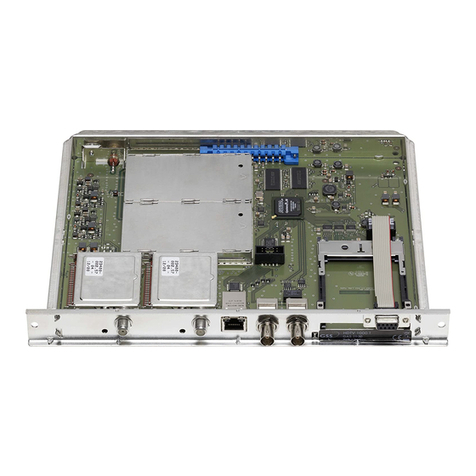
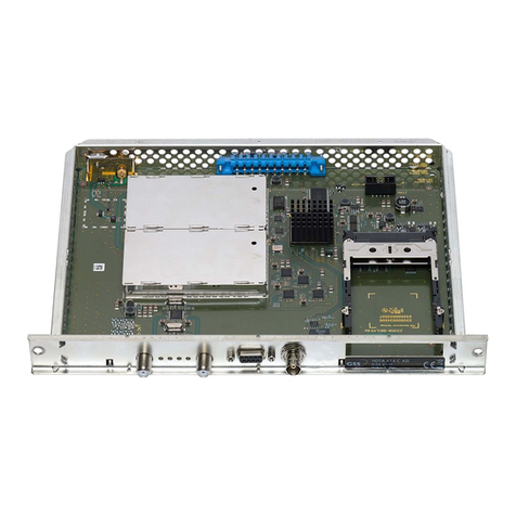
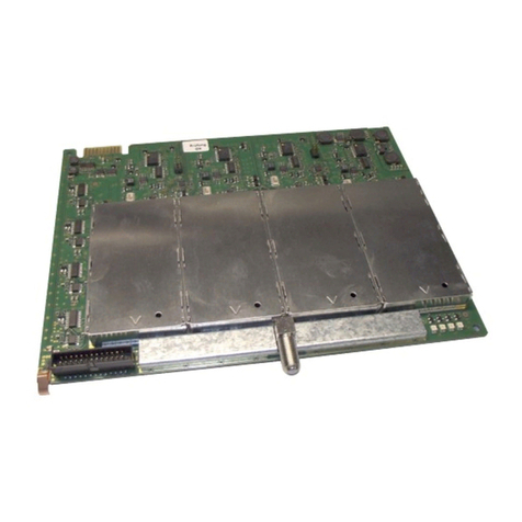
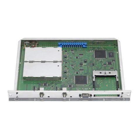
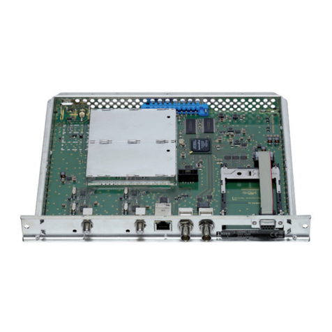
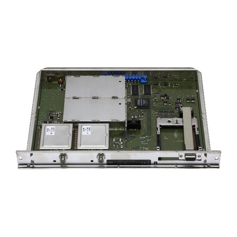
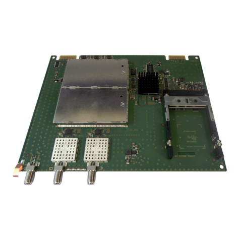
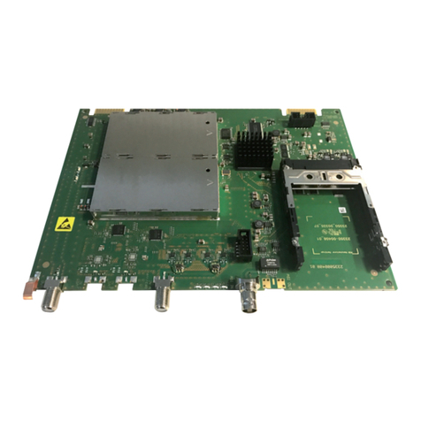
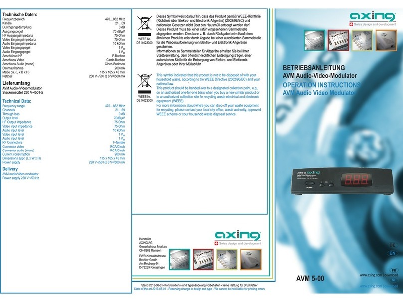
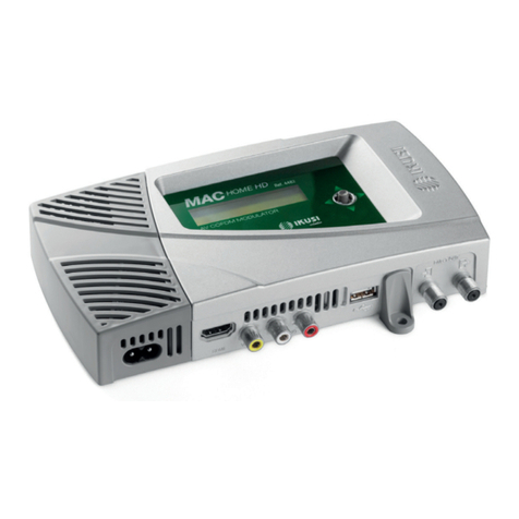
GSS HDTV 1000 ASI LAN User manual

1 Wichtige Informationen
• Montage,InstallationundServicesindvon
autorisierten Elektrofachkräften durchzu-
führen.
• BetriebsspannungderAnlagevorBeginn
von Montage- oder Servicearbeiten ab-
schalten.
•
Führen Sie Installations- und Servicearbeiten
nichtbeiGewitterndurch.
• Stellen Sie eine ausreichende Belüftung des
Gerätessicher.
• VermeidenSieKurzschlüsse!
•
DieNormenIEC/EN/DINEN50083bzw.IEC/
EN/DINEN60728,müsseneingehaltenwerden.
•
Beachten Sie die relevanten Normen, Vor-
schriften und Richtlinien zur Installation und
zumBetriebvonAntennenanlagen.
•
ÜberprüfenSiedieKopfstationaufdieinde-
ren Montageanleitung gelisteten Sicherheits-
vorschriften.
•
Schäden durch fehlerhaften Anschluss und/
oderunsachgemäßeHandhabungderCassette
sindvonjeglicherHaftungausgeschlossen.
• PrüfenSiedieSoftware-VersionenderKopfstati-
onundderCassetteundaktualisierenSiediese
falls erforderlich. Die aktuellen Software-Versi-
onenfindenSieunter
“www.gss.de”
.
Beachten Sie für weitergehende Informationen
zu Sicherheit, Montage und Programmierung die
Montageanleitungen der Cassette und der Kopf-
station, die Sie auf “www.gss.de” finden.
WennSiekeinenInternetzuganghaben,senden
wirIhnenaufAnfragegerneeineDVD.
1 Important information
• Assembly,installationandservicingshould
becarriedoutbyauthorisedelectricians.
• Switch off the operating voltage of the
systembeforebeginningwithassemblyor
servicework.
• Do not perform installation and service work
duringthunderstorms.
• Makesurethedeviceisadequatelyventilated.
• Avoidshortcircuits!
• The standards IEC/EN/DINEN50083 resp.
IEC/EN/DINEN60728mustbeobserved.
• Observe the relevant standards, regulations
andguidelinesontheinstallationandopera-
tionofantennasystems.
• Noliabilityisacceptedfordamagecausedby
faultyconnectionsorinappropriatehandlingof
thedevice.
•
Checkthehead-endstation
accordingtothe
safety instructions listed in their assembly in-
struction.
•
Testthesoftwareversionsofthehead-endsta-
tionandthecassetteandupdatethemifnec-
essary.Thecurrent softwareversionscanbe
foundat“www.gss.de”.
For further information on safety, installation and
programming please read the assembly instruc-
tions for the cassette and the head-end station
you will find at “www.gss.de”.
Ifyoudonothaveinternetaccess,wewillsend
youaDVDonrequest.
Head-End Digital Modulator HDTV
HDTV 1000 ASI LAN / HDTV 1001 C
Kurz-Montageanleitung
Brief Assembly Instruction
Deutsch English
CLASS
KLASSE
- 2 - HDTV 1000 ASI LAN / HDTV 1001 C
2 Kurzbeschreibung
Die Twin-Transmodulator-Cassette ist
ein QPSK-Umsetzer, der alle nach
DVB-S-/DVB-S2-
Standard modulierten
Programme
inzweiQAM-modulierteKa-
belsignalekonvertiert.
HDTV1001CkanndenTransportstrom
TSAüberdasCA-Modulverschlüsseln.
Der über die ASI-Buchse
(ASI – Asyn-
chronousSerialInterfacegem.DINEN
50083-9)
eingespeiste Transportstrom
kann in die Transportströme der Modu-
latoreneingefügtwerden.DerSignallauf
wird in den Menüs Eingangssignallauf
“INROUTE” und Ausgangssignallauf
”OUTROUTE”festgelegt.
Eingangssignallauf “INROUTE”
Menüeinstellung“A+ASI=1 B+ASI=2”
Menüeinstellung“A+B+ASI=1 ASI=2”
TS ATransportstrom 1
Transport stream 1
Transportstrom 2
Transport stream 2
SAT-Eingang ”A“
SAT input ”A“
ASI-Eingang
ASI input
SAT-Eingang ”B“
SAT input ”B“
Empfangsteil
Receiving stage
"A"
Empfangsteil
Receiving stage
"B"
TPS
CA-Modul
CA module
TPS
TS ASI
TS B
TS A
Transportstrom 1
Transport stream 1
Transportstrom 2
Transport stream 2
SAT-Eingang ”A“
SAT input ”A“
Empfangsteil
Receiving stage
"A"
CA-Modul
CA module
TPS
ASI-Eingang
ASI input
TS ASI
SAT-Eingang ”B“
SAT input ”B“
Empfangsteil
Receiving stage
"B"
TS B
2 Brief description
Thedoubletransmodulatorcassetteisa
QPSK-converter,whichconvertsallsta-
tions modulated according to DVB-S/
DVB-S2
standardintotwoQAM-modulat-
ed
cablesignals.
HDTV 1001 C is able to scramble the
transportstreamTSAviatheCAmodule.
ThetransportstreamfedviatheASIsock-
et
(ASI–AsynchronousSerialInterface
acc.DINEN50083-9)
canbeinserted
intothetransportstreamsofthemodula-
tors.
T
hesignal pathis setin themenu
itemsinputsignalpath
“INROUTE”and
outputsignalpath”OUTROUTE”
Input signal path “INROUTE”
Menusetting“A+ASI=1 B+ASI=2”
Menusetting“A+B+ASI=1 ASI=2”

- 3 - HDTV 1000 ASI LAN / HDTV 1001 C
Menüeinstellung“A+ASI=1 A+ASI=2”
Ausgangssignallauf “OUTROUTE”,
Menüeinstellung“ASI=>ASI”
Menüeinstellung
“1=>ASI ASI=>MA”
TS ATransportstrom 1
Transport stream 1
Transportstrom 2
Transport stream 2
SAT-Eingang ”A“
SAT input ”A“
ASI-Eingang
ASI input
Empfangsteil
Receiving stage
"A"
TPS
CA-Modul
CA module
TPS
TS ASI
Modulator
"B"
Modulator
"A"
Combiner
TS ASI
ASI-Eingang
ASI input
ASI-Ausgang
ASI output
HF-Ausgang
HF output
Transportstrom 1
Transport stream 1
Transportstrom 2
Transport stream 2
Modulator
"B"
Modulator
"A"
Combiner
TS ASI
ASI-Eingang
ASI input
Transportstrom 1
Transport stream 1
Transportstrom 2
Transport stream 2
ASI-Ausgang
ASI output
HF-Ausgang
HF output
Menusetting“A+ASI=1 A+ASI=2”
Output signal path “OUTROUTE”
Menusetting“ASI=>ASI”
Menusetting“1=>ASI ASI=>MA”

- 4 - HDTV 1000 ASI LAN / HDTV 1001 C
Menüeinstellung“2=>ASI ASI=>MB”
Die Cassette ist mit zwei Kanalzügen
(“
A
” und “
B
”) bestückt.
Der Kanalzug
“A”kannübereinentsprechendesCA-
Modul verschlüsselte Programme ent-
schlüsseln. Zwei Leuchtdioden geben
überihreFarbeeinenHinweisaufdie
Signalqualität und zeigen an, ob der
jeweilige Kanalzug eingeschaltet (LED
leuchtet)oderausgeschaltetist(s.Abb.
Seite8).
LED-Anzeige Bedeutung
grün Signalqualitätgut
gelb Signalqualitätminderwertig
rot keinSignal
aus Kanalzug(Modulator)ist
ausgeschaltet
FürdenBetriebdieserCassettemuss
die
Betriebssoftware des Bedienteils
mindestensderVersion“V 43“entspre-
chen.
DieCassetteistfürdenBetriebinden
KopfstationenSTC816,STC1200und
PST19-1vorgesehen.
Modulator
"B"
Modulator
"A"
Combiner
TS ASI
ASI-Eingang
ASI input
Transportstrom 1
Transport stream 1
Transportstrom 2
Transport stream 2
ASI-Ausgang
ASI output
HF-Ausgang
HF output
Menusetting“2=>ASI ASI=>MB”
The cassette is equipped with two
channelstrips(“A”and“B”).
Usingan
adequateCAmodulescrambledchan-
nels can be descrambled via channel
strip“A”.
TwoLEDsindicateiftherespectivechan-
nelstripisswitchedon(LEDilluminates)
oroff,andalsoprovideanindicationof
thesignalqualitybasedontheircolour
(seefigureonpage8).
LED indicator Indication
Green Signalqualityisgood
Yellow Signalqualityispoor
Red Nosignal
Off Thechannelstrip(modula-
tor)isswitchedoff
Tooperatethiscassettethesoftware
version of the control unit must be
“V 43”orhigher.
Thecassetteisintendedforuseinthe
STC 816, STC 1200 and PST19-1
head-endstations.

- 5 - HDTV 1000 ASI LAN / HDTV 1001 C
3 Cassette montieren
– BeachtenSie,dassdieKopfstation
vibrationsfreimontiertseinmuss.Ver-
meiden Sie z.B. die Montage der
KopfstationaneinemAufzugschacht
oder ähnlich vibrierenden Wand-
oderBodenkonstruktionen.
–Vor Montage oder Wechsel einer
CassetteNetzsteckerderKopfstation
ausderNetzsteckdoseziehen.
•Befestigungsschrauben 1 eines un-
bestückten Steckplatzes aus dem
HalterahmenderKopfstationheraus-
drehen.
•Cassette in diesenSteckplatzeinset-
zenundindasGehäuseschieben.
•Cassetteausrichtenundmitleichtem
DruckmitderPlatineundderHF-Sam-
melschienekontaktieren.
•Cassette mit den Schrauben 1 be-
festigen.
0°
1
1
CASSETTE
CASSETTE
CASSETTE
CASSETTE
CASSETTE
CASSETTE
CASSETTE
CASSETTE
CASSETTE
CASSETTE
CASSETTE
CASSETTE
MESSAUSGANG
A
ACHTUNG!
Vor dem Cassettenwechsel
unbedingt Netzstecker ziehen!
CAUTION!
Before changing cassettes remove
mains plug!
3 Installing the cassette
–
Ensure the head-end station is
mounted so it will not be able to vi-
brate. Avoid, for example, mounting
thehead-endstationontoaliftshaftor
anyotherwallorfloorconstructionthat
vibratesinasimilarway.
–Before installing or changing a cas-
setteunplugthepowercablefromthe
mainspowersocket.
•Remove the fastening screws 1 of
anunoccupiedslotfromthebracket
ofthehead-endstation.
•Insertthecassetteinthisslotandpush
itintothehousing.
•
Align the cassette and apply slight
pressure to connect it to the connec-
tionsoftheboardandtheHFbusbar.
•Fasten the cassette with the screws
1.

- 6 - HDTV 1000 ASI LAN / HDTV 1001 C
4 EMV-Vorschriften
UmdiegültigenEMV-Vorschrifteneinzu-
halten, ist es erforderlich, die von au-
ßen kommenden und die nach außen
führendenVerbindungenderKopfstati-
on über Kabel-Durchführungen herzu-
stellen.
Die Schirmdämpfung der Anschlussleitun-
gen für ASI und Antenne muss den An-
forderungen der “Klasse A” entsprechen.
Beachten Sie beim Einbau der Cas-
setteineineKopfstation,dieineinem
19”-Schrank installiert ist, dass die
von außen kommenden und nach au-
ßen führenden Verbindungen beim
19”-Schrank über Kabel-Durchführun-
genherzustellensind.
• Erforderliche Anzahl von Kabel-
Durchführungen in die vorgesehenen
Durchbrüche in der Kopf-
stationbzw.im19”-Schrank
einsetzen.
Die Kabel-Durchführungen
sind handelsüblich und
nicht im Lieferumfang ent-
halten.
Ziehen Sie die Muttern der Kabel-
Durchführungen so fest an, dass sich
dieuntergelegtenZahnscheibendurch
die Oberflächenbeschichtung drücken
und einen sicheren Kontakt zwischen
Gehäuse / 19”-Schrank und Kabel-
Durchführunggewährleisten.
4 EMC regulations
TocomplywiththecurrentEMCregu-
lations, it is necessary to connect the
lines leading in and out of the head-
endstation(e.g.cinch,HF)usingcable
terminals.
The attenuation of shielding of the con-
nection lines for ASI and antenna must
meet the requirements for “Class A”.
Whenmountingthecassetteinahead-
endstationwhichisinstalledina19”
cabinet,makesurethattheconnections
leadinginandoutatthe19”cabinet
aremadeusingcableterminals.
•
Insert the required number of stand-
ard cable terminals in the openings
provided (knock-outs) in
the head-end station or
the19”cabinet.
The cable terminals are
standard and are not in-
cludedinthescopeofde-
livery.
Tightenthenutsof thecable termi-
nalsuntiltheteethonthelockwashers
putunderthenutshavepenetratedthe
exteriorcoatingandagoodconnection
is made between the housing /
19”cabinetandcableterminal.

- 7 - HDTV 1000 ASI LAN / HDTV 1001 C
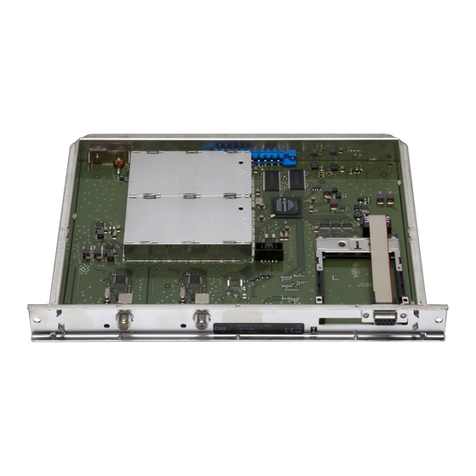
5 Die Cassette im Überblick
1 D-SUB-Buchse“RS232“
2 SchachtfüreinCA-Modul
3 ASI-Ausgang
4 ASI-Eingang
5 nichtbelegt
6
SAT-Eingang
(Tuner“
A
”)
7
Status-LEDKanalzug“
A
”
8 SAT-Eingang
(Tuner“
B
”)
9
Status-LEDKanalzug“
B
”
6 Cassette anschließen
•
SAT-Eingangskabel mit den Buchsen
SAT-Eingang
“
A
”
6
(Tuner“A”)und
SAT-Eingang
“
B
”
8
(Tuner“B”)ver-
binden.
•ASI-Verbindungenherstellen.
•KopfstationmitNetzspannungversor-
gen.
7 Software aktualisieren
Über die 9-polige D-SUB-Buchse
“RS 232” kann mittels eines PC oder
NotebooksundderSoftware“BE-Flash”
dieBetriebssoftwarederCassetteaktu-
alisiert werden. Die aktuelle Betriebs-
software finden Sie auf der Website
“www.gss.de”.
1
2
3
4
5
6
7
8
9
5 Overview of the cassette
1 D-SUBsocket“RS232“
2 SlotforCAmodule
3 ASIoutput
4 ASIinput
5 notused
6
SATinput
(tuner“
A
”)
7
StatusLEDchannelstrip“
A
”
8 SATinput
(tuner“
B
”)
9
StatusLEDchannelstrip“
B
”
6 Connecting the cassette
•PlugtheSATinputcablesintotheSAT
inputsocketsSAT input
“
A”6 (tun-
er“A”)andSAT input
“
B”8 (tuner
“B”).
•ConnecttheASIsockets.
•Connectthehead-endstation tothe
mains.
7 Updating the software
Theoperatingsoftwareofthecassette
can be updated via the 9-Pin D-SUB
socket “RS232” using a PC or note-
bookandthesoftware“BE-Flash”.You
canfindthecurrentoperatingsoftware
onthewebsite“www.gss.de”.

- 8 - HDTV 1000 ASI LAN / HDTV 1001 C
8 CA-Modul nachrüsten
–
VergewissernSiesichbeimLiefe-
ranten oder Hersteller des zu ver-
wendendenCA-Moduls,obeszum
DecodierenvonmehrerenProgram-
mengeeignetist.
–Von den Programmanbietern veran-
lasste Änderungen der Strukturen in
den Programmdaten können diese
Funktion beeinträchtigen oder sogar
unterbinden.
–
Beachten Sie für die Bedienung des
CA-Moduls die zugehörige Bedie-
nungsanleitung des jeweiligen Anbie-
ters.
•SmartcardsoindasCA-Modulschie-
ben,dassderChip3aufderSmart-
card1zurdickerenSeite(oben)des
CA-Moduls2zeigt.
•CA-Modul so in den Schacht 4
einsetzen, dass die Oberseite des
CA-Moduls zur RS-232-Buchse der
Cassettezeigt.
•CA-Modul ohne zu verkanten in die
Führungsschienen des CA-Schachts
4 schiebenundmitdemCommon-
Interfacekontaktieren.
34 12
8 Retrofitting a CA module
–
Checkwiththedistributorormanu-
factureroftheCAmoduletobeused
toensurethatitissuitablefordecod-
ingseveralchannels.
–Any changes made by programme
providerstothestructuresinthepro-
gramme data might impair or even
preventthisfunction.
–WhenworkingwiththeCAmodule,
pleasereadthecorrespondingoper-
atingmanualfromtherespectivepro-
vider.
•InsertthesmartcardintotheCAmod-
ulesothatthechip
3
onthesmart
card
1
facesthethickerside(top)of
theCAmodule
2
.
•InserttheCAmoduleintotheslot
4
withthetop side ofthe CAmodule
facingtheRS-232socketofthecas-
sette.
•PushtheCAmodulewithoutcanting
intotheguiderailsoftheCAslot
4
and contact it to the common inter-
face.

- 9 - HDTV 1000 ASI LAN / HDTV 1001 C
9 Das Bedienfeld im Überblick
Programmieren Sie die
Cassette über die Tasten
des Bedienteils.
Die Me-
nüs bzw. Menüpunkte
können Sie schrittweise
überdieTastatur desBe-
dienteilsanwählen.
“blättert”Menüsvorwärts.
wählenParameterinden
Menüs.
stellenWerteein,
lösenAktionenaus.
wähltUntermenüs.
“blättert”Menüsrückwärts.
speichertalleEingaben.
ImMenü"DEFAULTS"->
Werkseinstellungen
10 Hinweise zur Programmierung
•Messempfänger am HF-Ausgang
bzw.
MessausgangderKopfstati
on
anschließen.
•Ausgangskanal der Cassette einstel-
len und Messempfänger auf diesen
Kanalabstimmen.
•Gegebenenfalls Modulator einschal-
ten.ObdieKanalzügeeingeschaltet
sind, wird durch jeweils eine leuch-
tendeStatus-LEDangezeigt.
9 The control panel at a glance
Programme the Cassette
usingthekeysonthehead-
end station´s control unit.
The keypad ofthe control
unitisusedtoscrollthrough
themenusandmenuitems
gradually.
scrollsforwardthroughthe
menus.
selectparametersfromthe
menus.
setvaluesandtriggeractions.
selectssub-menus.
scrollsbackwardthroughthe
menus
.
savesallentries.
Inmenu"DEFAULTS"->
factorydefaults
10 Notes on programming
•ConnectthetestreceivertotheHFout-
putorthetestoutputofthehead-end
station.
•Settheoutputchannelofthe
cassette
andadjusttheTVtestreceivertothis
channel.
•Switchonthemodulatorifnecessary.
Foreachchannelstrip,thereisansta-
tusLEDwhichindicatesifthechannel
stripisswitchedon.

- 10 - HDTV 1000 ASI LAN / HDTV 1001 C
11 Hinweise zur Pegeleinstellung
•Ausgangspegel der Kanalzüge “A”
und“B”angleichen,wennderPegel-
unterschied≥ 1dBbeträgt.
•
UmStörungeninnerhalbderKopfsta-
tionundderKabelanlagezuvermei-
den,müssenSiedenAusgangspegel
derCassetteimVergleichzuanalogen
Cassettenbei64QAMum10dBund
bei256QAMum4dBabsenken.
12 Programmierablauf
11 Notes on level setting
•Balancetheoutputlevelsofthechan-
nelstrips“A”and“B”ifthedifference
inlevelis≥ 1dB.
•Inordertopreventinterferencewithin
the head-end station and the cable
system,theoutputlevelofthecassette
must be decreased by 10 dB com-
pared to analogue cassettes at 64
QAM,andby4dBat256QAM.
12 Programming procedure
Bx 4A/B
Freq.
OUTPUT
Channel / Freq.
Bx 4A/B
850.00 MHz
OUTPUT
on
Bx 4A/B
27500
SYMBOL
DVB-S
Bx 4A/B
11835 -0.7
FREQ
CN 15
▶
◀/
▶
◀/
▶
◀/
on / off
▶
◀/
▶
◀/
▶
◀/
Bx 4A/B
-3 dB
LEVEL
Bx 4A/B
10600 MHz
LNB
0 … -10 dB
Bx 4A/B
15.3 dB
C/N
(+ 11.3) OK
Anzeige: Signalqualität
Display: Signal quality
▶
◀/
DVB-S / DVB-S 2 …
Bx 4A/B
Filter
PROGRAM
off
01/10Bx 4A TV +
Das Erste
Programme entfernen / hinzufügen
Removing / activating stations
nächster Service (Programm)
next service (station)
▶
◀/
02/19Bx 4B TV +
SWF3
Programme entfernen / hinzufügen
Removing / activating stations
nächster Service (Programm)
next service (station)
▶
◀/
01/10ASI TV +
. . . . .
Programme entfernen / hinzufügen
Removing / activating stations
nächster Service (Programm)
next service (station)
▶
◀/
M
M
M
M
B
A
Bx 4A/B
SR=6900 (6325)
STUFFING
Bx 4A/B
Single Carrier
FAILURE
Bx 4A/B
256-QAM
QAM
normal
▶
◀/
▶
◀/
▶
◀/
4 … 256 normal / inverse
Null Packets … Single Carrier
Bx 4A/B
off
NIT
=> Make
Bx 4A/B
0x0001,0100
TS/ONID
off
on / off
▶
▶
on / off Make
Bx 4A/B
PID 0x0000
DROP
off
Bx 4A/B
0XDE00
CAT-ID
off
▶
◀/
Bx 4
Defaults
FACTORY
=>
Bx 4
STORE
FACTORY
=> M
on / off
▶
◀/
▶
◀/
on / off
▶
◀/
auf Werkseinstellung
zurücksetzen und speichern
reset to factory defaults
and store
Kanalzug “A” mit CA-Modul
Channel strip “A“ with CA module
▶
▶
◀/
on / off
▶
◀/
Bx 4
Line A <=
LINE
=> Line B Line A / Line B
B
A
Ein / On
BE–Remote
please wait …
V 43
Box 4
V 16
DVBS2-TPM
– – –
+
t > 10 s
Bx 4
A+ASI=1
INROUTE
B+ASI=2 A+ASI=1 B+ASI=2 /
A+B+ASI=1 ASI=2 /
A+ASI=1 A+ASI=2
1=>ASI ASI=>MA
2=>ASI ASI=>MB
ASI=>ASI
Bx 4
ASI=>ASI
OUTROUTE Bx 4
108000 KBits
ASI RATE
188 / 204
positive / negativ
continuous / burst
Bx 4
188 pos. cont.
ASI OPTION
▶
◀/
▶
◀/
Bx 4A/B
0x0000 –> 0000
REMAP
off
Bx 4A
Menu <=
CA
=> Edit
*) Die angezeigte Information ist
abhängig vom verwendeten
CA-Modul.
The information displayed is
dependent on the CA module
used.
Bx 4A 01/03
Information *)
MENU
Bx 4A TV X
. . . .
04/09 X – entschlüsseln
descrambling
0 – nicht entschlüsseln
no descrambling
X / 0
nächster Service
next service
Bx 4A
PID Check
CA
on
▶
◀
on / off
▶
◀/
Bx 4A
scramble
CA
scramble / descramble
scramble
descramble
Bx 1A
C5-12,S3-24
TWIN-SAT
C07
Böx 4
C5-12,S3-24
TWIN-SAT
C07
Box 5
..............
..............
..............
Box …
………
……
……
Seite/Page13

- 11 - HDTV 1000 ASI LAN / HDTV 1001 C
Bx 4A/B
Freq.
OUTPUT
Channel / Freq.
Bx 4A/B
850.00 MHz
OUTPUT
on
Bx 4A/B
27500
SYMBOL
DVB-S
Bx 4A/B
11835 -0.7
FREQ
CN 15
▶
◀/
▶
◀/
▶
◀/
on / off
▶
◀/
▶
◀/
▶
◀/
Bx 4A/B
-3 dB
LEVEL
Bx 4A/B
10600 MHz
LNB
0 … -10 dB
Bx 4A/B
15.3 dB
C/N
(+ 11.3) OK
Anzeige: Signalqualität
Display: Signal quality
▶
◀/
DVB-S / DVB-S 2 …
Bx 4A/B
Filter
PROGRAM
off
01/10Bx 4A TV +
Das Erste
Programme entfernen / hinzufügen
Removing / activating stations
nächster Service (Programm)
next service (station)
▶
◀/
02/19Bx 4B TV +
SWF3
Programme entfernen / hinzufügen
Removing / activating stations
nächster Service (Programm)
next service (station)
▶
◀/
01/10ASI TV +
. . . . .
Programme entfernen / hinzufügen
Removing / activating stations
nächster Service (Programm)
next service (station)
▶
◀/
M
M
M
M
B
A
Bx 4A/B
SR=6900 (6325)
STUFFING
Bx 4A/B
Single Carrier
FAILURE
Bx 4A/B
256-QAM
QAM
normal
▶
◀/
▶
◀/
▶
◀/
4 … 256 normal / inverse
Null Packets … Single Carrier
Bx 4A/B
off
NIT
=> Make
Bx 4A/B
0x0001,0100
TS/ONID
off
on / off
▶
▶
on / off Make
Bx 4A/B
PID 0x0000
DROP
off
Bx 4A/B
0XDE00
CAT-ID
off
▶
◀/
Bx 4
Defaults
FACTORY
=>
Bx 4
STORE
FACTORY
=> M
on / off
▶
◀/
▶
◀/
on / off
▶
◀/
auf Werkseinstellung
zurücksetzen und speichern
reset to factory defaults
and store
Kanalzug “A” mit CA-Modul
Channel strip “A“ with CA module
▶
▶
◀/
on / off
▶
◀/
Bx 4
Line A <=
LINE
=> Line B Line A / Line B
B
A
Ein / On
BE–Remote
please wait …
V 43
Box 4
V 16
DVBS2-TPM
– – –
+
t > 10 s
Bx 4
A+ASI=1
INROUTE
B+ASI=2 A+ASI=1 B+ASI=2 /
A+B+ASI=1 ASI=2 /
A+ASI=1 A+ASI=2
1=>ASI ASI=>MA
2=>ASI ASI=>MB
ASI=>ASI
Bx 4
ASI=>ASI
OUTROUTE Bx 4
108000 KBits
ASI RATE
188 / 204
positive / negativ
continuous / burst
Bx 4
188 pos. cont.
ASI OPTION
▶
◀/
▶
◀/
Bx 4A/B
0x0000 –> 0000
REMAP
off
Bx 4A
Menu <=
CA
=> Edit
*) Die angezeigte Information ist
abhängig vom verwendeten
CA-Modul.
The information displayed is
dependent on the CA module
used.
Bx 4A 01/03
Information *)
MENU
Bx 4A TV X
. . . .
04/09 X – entschlüsseln
descrambling
0 – nicht entschlüsseln
no descrambling
X / 0
nächster Service
next service
Bx 4A
PID Check
CA
on
▶
◀
on / off
▶
◀/
Bx 4A
scramble
CA
scramble / descramble
scramble
descramble
Bx 1A
C5-12,S3-24
TWIN-SAT
C07
Böx 4
C5-12,S3-24
TWIN-SAT
C07
Box 5
..............
..............
..............
Box …
………
……
……
Seite/Page13

- 12 - HDTV 1000 ASI LAN / HDTV 1001 C
Bx 4A/B
Freq.
OUTPUT
Channel / Freq.
Bx 4A/B
850.00 MHz
OUTPUT
on
Bx 4A/B
27500
SYMBOL
DVB-S
Bx 4A/B
11835 -0.7
FREQ
CN 15
▶
◀/
▶
◀/
▶
◀/
on / off
▶
◀/
▶
◀/
▶
◀/
Bx 4A/B
-3 dB
LEVEL
Bx 4A/B
10600 MHz
LNB
0 … -10 dB
Bx 4A/B
15.3 dB
C/N
(+ 11.3) OK
Anzeige: Signalqualität
Display: Signal quality
▶
◀/
DVB-S / DVB-S 2 …
Bx 4A/B
Filter
PROGRAM
off
01/10Bx 4A TV +
Das Erste
Programme entfernen / hinzufügen
Removing / activating stations
nächster Service (Programm)
next service (station)
▶
◀/
02/19Bx 4B TV +
SWF3
Programme entfernen / hinzufügen
Removing / activating stations
nächster Service (Programm)
next service (station)
▶
◀/
01/10ASI TV +
. . . . .
Programme entfernen / hinzufügen
Removing / activating stations
nächster Service (Programm)
next service (station)
▶
◀/
M
M
M
M
B
A
Bx 4A/B
SR=6900 (6325)
STUFFING
Bx 4A/B
Single Carrier
FAILURE
Bx 4A/B
256-QAM
QAM
normal
▶
◀/
▶
◀/
▶
◀/
4 … 256 normal / inverse
Null Packets … Single Carrier
Bx 4A/B
off
NIT
=> Make
Bx 4A/B
0x0001,0100
TS/ONID
off
on / off
▶
▶
on / off Make
Bx 4A/B
PID 0x0000
DROP
off
Bx 4A/B
0XDE00
CAT-ID
off
▶
◀/
Bx 4
Defaults
FACTORY
=>
Bx 4
STORE
FACTORY
=> M
on / off
▶
◀/
▶
◀/
on / off
▶
◀/
auf Werkseinstellung
zurücksetzen und speichern
reset to factory defaults
and store
Kanalzug “A” mit CA-Modul
Channel strip “A“ with CA module
▶
▶
◀/
on / off
▶
◀/
Bx 4
Line A <=
LINE
=> Line B Line A / Line B
B
A
Ein / On
BE–Remote
please wait …
V 43
Box 4
V 16
DVBS2-TPM
– – –
+
t > 10 s
Bx 4
A+ASI=1
INROUTE
B+ASI=2 A+ASI=1 B+ASI=2 /
A+B+ASI=1 ASI=2 /
A+ASI=1 A+ASI=2
1=>ASI ASI=>MA
2=>ASI ASI=>MB
ASI=>ASI
Bx 4
ASI=>ASI
OUTROUTE Bx 4
108000 KBits
ASI RATE
188 / 204
positive / negativ
continuous / burst
Bx 4
188 pos. cont.
ASI OPTION
▶
◀/
▶
◀/
Bx 4A/B
0x0000 –> 0000
REMAP
off
Bx 4A
Menu <=
CA
=> Edit
*) Die angezeigte Information ist
abhängig vom verwendeten
CA-Modul.
The information displayed is
dependent on the CA module
used.
Bx 4A 01/03
Information *)
MENU
Bx 4A TV X
. . . .
04/09 X – entschlüsseln
descrambling
0 – nicht entschlüsseln
no descrambling
X / 0
nächster Service
next service
Bx 4A
PID Check
CA
on
▶
◀
on / off
▶
◀/
Bx 4A
scramble
CA
scramble / descramble
scramble
descramble
Bx 1A
C5-12,S3-24
TWIN-SAT
C07
Böx 4
C5-12,S3-24
TWIN-SAT
C07
Box 5
..............
..............
..............
Box …
………
……
……
nur/onlyHDTV1001C

- 13 - HDTV 1000 ASI LAN / HDTV 1001 C
13 Abschließende Arbeiten
Um die gültigen EMV-Vorschriften
einzuhalten,isteserforderlichnachder
Montage der Kopfstation, der Nach-
rüstungvonZubehörunddemBestücken
derCassetten,alleKabel-Verschraubun-
gen,Kabel-DurchführungenundAbde-
ckungensorgfältigzubefestigen.
•Ausgangspegel der anderen Casset-
ten messen und je nach verwende-
ter Kopfstation mit den zugehörigen
Pegelstellern bzw. der Software auf
einen einheitlichen Ausgangspegel
einstellen.
13 Final procedures
Afterinstallingthehead-endstation,
upgradingaccessoriesorinstallingcas-
settes,itisnecessarytotightenallcable
connections,cableterminalsandcover
screwsinordertomaintaincompliance
withcurrentEMCregulations.
•Measuretheoutputlevelsoftheother
cassettesandtunethemtoauniform
outputlevelusingtheappropriatelev-
elcontrolsorsoftwaredependenton
thehead-endstationused.
Bx 4A/B
Freq.
OUTPUT
Channel / Freq.
Bx 4A/B
850.00 MHz
OUTPUT
on
Bx 4A/B
27500
SYMBOL
DVB-S
Bx 4A/B
11835 -0.7
FREQ
CN 15
▶
◀/
▶
◀/
▶
◀/
on / off
▶
◀/
▶
◀/
▶
◀/
Bx 4A/B
-3 dB
LEVEL
Bx 4A/B
10600 MHz
LNB
0 … -10 dB
Bx 4A/B
15.3 dB
C/N
(+ 11.3) OK
Anzeige: Signalqualität
Display: Signal quality
▶
◀/
DVB-S / DVB-S 2 …
Bx 4A/B
Filter
PROGRAM
off
01/10Bx 4A TV +
Das Erste
Programme entfernen / hinzufügen
Removing / activating stations
nächster Service (Programm)
next service (station)
▶
◀/
02/19Bx 4B TV +
SWF3
Programme entfernen / hinzufügen
Removing / activating stations
nächster Service (Programm)
next service (station)
▶
◀/
01/10ASI TV +
. . . . .
Programme entfernen / hinzufügen
Removing / activating stations
nächster Service (Programm)
next service (station)
▶
◀/
M
M
M
M
B
A
Bx 4A/B
SR=6900 (6325)
STUFFING
Bx 4A/B
Single Carrier
FAILURE
Bx 4A/B
256-QAM
QAM
normal
▶
◀/
▶
◀/
▶
◀/
4 … 256 normal / inverse
Null Packets … Single Carrier
Bx 4A/B
off
NIT
=> Make
Bx 4A/B
0x0001,0100
TS/ONID
off
on / off
▶
▶
on / off Make
Bx 4A/B
PID 0x0000
DROP
off
Bx 4A/B
0XDE00
CAT-ID
off
▶
◀/
Bx 4
Defaults
FACTORY
=>
Bx 4
STORE
FACTORY
=> M
on / off
▶
◀/
▶
◀/
on / off
▶
◀/
auf Werkseinstellung
zurücksetzen und speichern
reset to factory defaults
and store
Kanalzug “A” mit CA-Modul
Channel strip “A“ with CA module
▶
▶
◀/
on / off
▶
◀/
Bx 4
Line A <=
LINE
=> Line B Line A / Line B
B
A
Ein / On
BE–Remote
please wait …
V 43
Box 4
V 16
DVBS2-TPM
– – –
+
t > 10 s
Bx 4
A+ASI=1
INROUTE
B+ASI=2 A+ASI=1 B+ASI=2 /
A+B+ASI=1 ASI=2 /
A+ASI=1 A+ASI=2
1=>ASI ASI=>MA
2=>ASI ASI=>MB
ASI=>ASI
Bx 4
ASI=>ASI
OUTROUTE Bx 4
108000 KBits
ASI RATE
188 / 204
positive / negativ
continuous / burst
Bx 4
188 pos. cont.
ASI OPTION
▶
◀/
▶
◀/
Bx 4A/B
0x0000 –> 0000
REMAP
off
Bx 4A
Menu <=
CA
=> Edit
*) Die angezeigte Information ist
abhängig vom verwendeten
CA-Modul.
The information displayed is
dependent on the CA module
used.
Bx 4A 01/03
Information *)
MENU
Bx 4A TV X
. . . .
04/09 X – entschlüsseln
descrambling
0 – nicht entschlüsseln
no descrambling
X / 0
nächster Service
next service
Bx 4A
PID Check
CA
on
▶
◀
on / off
▶
◀/
Bx 4A
scramble
CA
scramble / descramble
scramble
descramble
Bx 1A
C5-12,S3-24
TWIN-SAT
C07
Böx 4
C5-12,S3-24
TWIN-SAT
C07
Box 5
..............
..............
..............
Box …
………
……
……
Seite/Page10
Seite/Page 11

- 14 - HDTV 1000 ASI LAN / HDTV 1001 C
14 Technische Daten 14 Technical data
HF-Eingang HF Input
Frequenzbereich..............................925 … 2150 MHz.............................. Frequencyrange
Pegelbereich..................................60 dBμV … 80 dBμV.................................... Levelrange
Eingangsimpedanz.................................... 75 Ω........................................Inputimpedance
DVB-S-Modi.............................QPSK 1/2, 2/3, 3/4, 5/6, 7/8........................... DVB-Smodes
DVB-S2-Modi................QPSK 1/2, 3/5, 2/3, 3/4, 4/5, 5/6, 8/9, 9/10.............. DVB-S2modes
8PSK 3/5 , 2/3 , 3/4 , 5/6 , 8/9 , 9/10
SymbolrateDVB-S....................... QPSK: 2 … 45 MSymb/s.......................SymbolrateDVB-S
SymbolrateDVB-S2.................... QPSK: 10 … 30 MSymb/s....................SymbolrateDVB-S2
8PSK: 10 … 31 MSymb/s
HF-Ausgang HF output
Kanäle.................................................S21 … C69............................................. Channels
Frequenzbereich......................... 42.0 MHz … 860.0 MHz......................... Frequencyrange
Ausgangspegel................................... typ. 97 dBμV........................................ Outputlevel
Ausgangsimpedanz................................... 75 Ω.....................................Outputimpedance
Anschlüsse Connections
HF-EingängeF-Buchsen75Ω.........................2............................... HFinputsFsockets75Ω
HF-AusgangIEC-Buchse75Ω.........................1.............................HFoutputIECsocket75Ω
ASI-EingangBNC-Buchse75Ω......................1........................... ASIinputBNCsocket75Ω
ASI-AusgangBNC-Buchse75Ω.....................1..........................ASIoutputBNCsocket75Ω
Anschlussleiste.................................. 20-polig/20-pin..............................
Connectionstrip
(fürVersorgungsspannungenundSteuerleitungen) (forsupplyvoltagesandcontrolcircuits)
CommonInterface........................................1.....................................
CommonInterface
(mehrereProgrammeentschlüsselbar)...........................................(severalstationscanbedescrambled)
Fernwartung Remote maintenance
Fernbedienbar(überPSW1000*)............ ja / yes..... Remotelycontrollable(viaPSW1000*)
Fernupdate(überBEflash*)....................... ja / yes.................... Remoteupdate(viaBEflash*)
(*undeineentsprechendeManagementeinheit) (*andacorrespondingmanagementunit)
Lieferumfang Packing contents
Cassetten....................................................1.................................................... Cassettes
HF-Kabel.....................................................2................................................... HFcables
Kurzmontageanleitung..................................1............................ Briefassemblyinstructions

- 15 - HDTV 1000 ASI LAN / HDTV 1001 C
15 Kanal- und Frequenztabellen 15 Channel and frequency tables
VorschlagfüreinFrequenzraster(8MHz)imBandI/III
Advice for a frequency grid (8 MHz) in the Band I/III
CCIR–Hyperband(Frequenzraster/Frequency grid 8 MHz)
CCIR–BandIV/V(Frequenzraster/Frequency grid 8 MHz)
Frequenzraster
Frequencygrid
[MHz
]
42.00
50.00
58.00
66.00
74.00
Frequenzraster
Frequencygrid
[MHz
]
82.00
114.00
122.00
130.00
138.00
Frequenzraster
Frequencygrid
[MHz
]
146.00
154.00
162.00
170.00
178.00
Frequenzraster
Frequencygrid
[MHz
]
186.00
194.00
202.00
210.00
218.00
Frequenzraster
Frequencygrid
[MHz
]
226.00
234.00
242.00
250.00
258.00
Frequenzraster
Frequencygrid
[MHz
]
266.00
274.00
282.00
290.00
298.00
Kanal
Channel
Kanalmittenfrequenz
Channelcentrefrequency
[MHz
]
S21 306.00
S22 314.00
S23 322.00
S24 330.00
S25 338.00
Kanal
Channel
Kanalmittenfrequenz
Channelcentrefrequency
[MHz
]
S26 346.00
S27 354.00
S28 362.00
S29 370.00
Kanal
Channel
Kanalmittenfrequenz
Channelcentrefrequency
[MHz
]
S30 378.00
S31 386.00
S32 394.00
S33 402.00
Kanal
Channel
Kanalmittenfrequenz
Channelcentrefrequency
[MHz
]
S34 410.00
S35 418.00
S36 426.00
S37 434.00
Kanal
Channel
Kanalmittenfrequenz
Channelcentrefrequency
[MHz
]
S38 442.00
S39 450.00
S40 458.00
S41 466.00
C21 474.00
C22 482.00
C23 490.00
C24 498.00
C25 506.00
C26 514.00
C27 522.00
C28 530.00
C29 538.00
C30 546.00
C31 554.00
C32 562.00
C33 570.00
C34 578.00
C35 586.00
C36 594.00
C37 602.00
C38 610.00
C39 618.00
C40 626.00
C41 634.00
C42 642.00
C43 650.00
C44 658.00
C45 666.00
C46 674.00
C47 682.00
C48 690.00
C49 698.00
C50 706.00
C51 714.00
C52 722.00
C53 730.00
C54 738.00
C55 746.00
C56 754.00
C57 762.00
C58 770.00
C59 778.00
C60 786.00
C61 794.00
C62 802.00
C63 810.00
C64 818.00
C65 826.00
C66 834.00
C67 842.00
C68 850.00
C69 858.00

Electronic devices should never be dis-
posedofinthehouseholdrubbish.Inac-
cordancewithdirective2002/96/ECof
theEuropeanParliamentandtheEurope-
an Council from January 27, 2003 which ad-
dresses old electronic and electrical devices,
suchdevicesmustbedisposedofatadesignat-
edcollectionfacility.Attheendofitsservicelife,
please take yourdevice to oneof these public
collectionfacilitiesforproperdisposal.
Änderungenvorbehalten.TechnischeAngabenohneGewähr. ©byGSSGmbH V16/08122010
Alterationsreserved.TechnicaldataE.&O.E. 266009412003
Service:
Phone: +49(0)911/7032221
Fax: +49(0)911/7032326
Email: ser[email protected]
GrundigSATSystemsGmbH•BeuthenerStraße43•D-90471Nürnberg
Elektronische Geräte gehören nicht in
den Hausmüll, sondern müssen gemäß
derRichtlinie2002/96/EGdesEuropäi-
schen Parlaments und desEuropäischen
Rates vom 27. Januar 2003 über Elektro- und
Elektronik-Altgeräte fachgerecht entsorgt wer-
den.BittegebenSiediesesGerätamEndesei-
ner Verwendung zur Entsorgung an den dafür
vorgesehenenöffentlichenSammelstellenab.
Other manuals for HDTV 1000 ASI LAN
1
This manual suits for next models
1
Table of contents
Other GSS Modulator manuals

GSS
GSS SMCIP 401 ASI User manual

GSS
GSS HDMC 1000 C User manual

GSS
GSS HDTV 1000 FM User manual

GSS
GSS HDTV 1000 TD User manual

GSS
GSS HDTA 614 C ASI User manual

GSS
GSS STI 1932 CT User manual

GSS
GSS HDM 660 T User manual

GSS
GSS HDTV 1000 ASI LAN User manual

GSS
GSS STC 160 User manual

GSS
GSS HDMT 1290 User manual