upcom UC-350E User manual

UC-350E+ Encoder
User’s Manual
Date : 2014-04-23
Version: 1.4
NMS Version: 5.0.20
SW: 0.07F
HW: 1.0

DIRECTORY
CHAPTER 1 PRODUCT OUTLINE!.................................................................................................!1!
1.1!OUTLINE!...........................................................................................................................................!1!
1.2!FEATURES!........................................................................................................................................!1!
1.3!SPECIFICATIONS!............................................................................................................................!1!
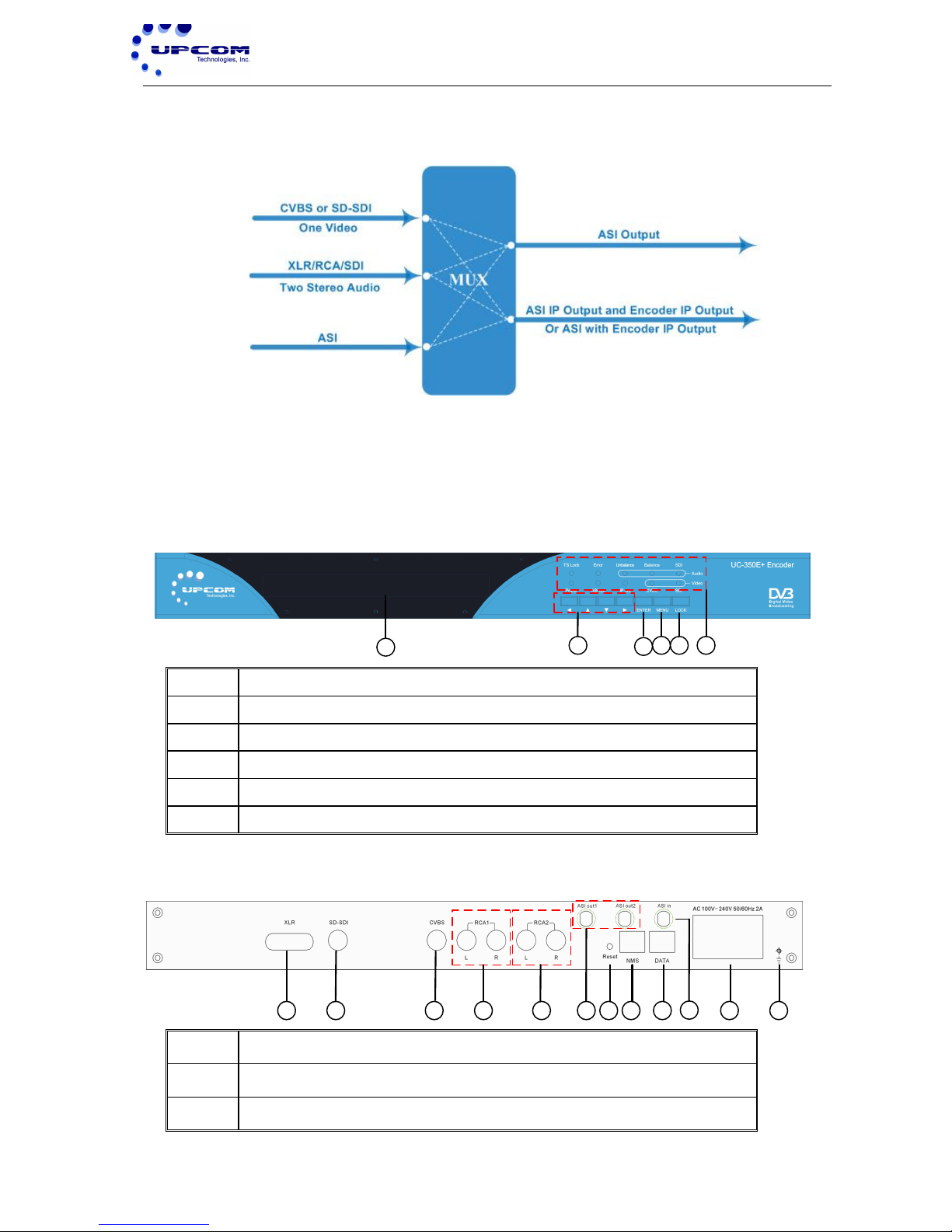
1.4!INNER!PRINCIPLE!..........................................................................................................................!3!
1.5!APPEARANCE!AND!DESCRIPTION!............................................................................................!3!
CHAPTER 2 INSTALLATION GUIDE!............................................................................................!4!
2.1!ACQUISITION!CHECK!....................................................................................................................!4!
2.2!INSTALLATION!PREPARATION!.................................................................................................!4!
2.3!WIRE!CONNECTIONS!....................................................................................................................!6!
2.4!SIGNAL!CABLE!CONNECTION!.....................................................................................................!7!
CHAPTER 3 OPERATION!...............................................................................................................!10!
3.1!INITIALIZING!................................................................................................................................!10!
3.2!GENERAL!SETTING!......................................................................................................................!11!
CHAPTER 4 NMS SETTING!...........................................................................................................!23!
4.1!INSTALLATION!.............................................................................................................................!23!
4.2!SOFTWARE!OPERATION!...........................................................................................................!23!
4.3!UC‐350E!MPEG‐2/H.264!SD!ENCODER!OPERATION!........................................................!29!
CHAPTER 5 TROUBLESHOOTING!............................................................................................!45!
CHAPTER 6 PACKING LIST!..........................................................................................................!46!

UC-350E + ) Encod e r) User ’s ) M anu a l)
1
Chapter 1
Product Outline
1.1!Outline! !
The UC-350E+ Encoder is Upcom Technology’s newest professional SD Video & Audio
encoding and multiplexing device with full functionality. It has one video along with two
simultaneous audio encoders, which support MPEG-2 and H.264 encoding types.
Furthermore, it can support MPEG-1 Audio layer Ⅱ, LC-ACC, HE-AAC V2, and can
support ultra low video bit-rate (0.25~15Mbps for H.264 encoding, and 0.5~15Mbps for
MPEG-2 encoding). Moreover, it has one ASI input interface and can multiplex the
encoder channels while giving ASI/IP output simultaneously.
1.2!Features!
Support H.264, MPEG2 Encoding.
MPEG1 Audio Layer Ⅱ, LC-AAC, HE-AAC V2
Support 4 Mono Encoding.
Support VBR/CBR Video Encoding.
Support Ultra Low Bit-Rate Encoding.
Support 1xSPTS UDP IP Output.
Real-time Output Bit-Rate monitoring.
LCD / Keyboard and NMS operation.
1.3!Specifications!
Input
2*XLR input,1*SD-SDI input
1*CVBS input, 2*RCA inputs
1*ASI input, BNC interface
Video
Resolution
PAL:720*576/352*288/320*240/320*180/176*144/
160*120/160*90@50Hz

UC-350E + ) Encod e r) User ’s ) M anu a l)
2
NTSC:720*480/352*288/320*240/320*180/176*144/
160*120/160*[email protected]
Encoding
MPEG-2 /H.264
Bit rate
0.25~15Mbps for H.264 Encoding
0.5~15Mbps for MPEG-2 Encoding
Rate Control
ConstantBitRate/VariableBitRate
GOP Structure
IBBP
Advanced
Pretreatment
De-interlacing, noise reduction, sharpening
Audio
Encoding
MPEG1 Audio Layer Ⅱ,LC-AAC,HE-AAC V2
Sampling rate
48KHz
Bit-rate
64Kb/s~384Kb/s (each channel)
Multiplexing
1 ASI input multiplexed with local 1 channel TS
Stream output
2 *ASI outputs, BNC interface
SPTS over UDP,10/100Base-T Ethernet interface (UDP
unicast / multicast)
System function
LCD/keyboard operation, NMS support, Ethernet software
upgrade
English control interface
General
Dimensions
482mm×455mm×44.5mm (WxDxH)
Approx Weight
4Kg
Temperature
Range
0~45℃(operation),-20~80℃(storage)
Power
Requirements
AC 100V±10%,50/60Hz or AC 240V±10%,50/60Hz
Power
Consumption
17.6W
!
!
!
!

UC-350E + ) Encod e r) User ’s ) M anu a l)
3
1.4!Inner!Architecture!
1.5!Appearance!and!Description!
Front Panel Illustration
1234 5 6
1
LCD Window
2
Left /Right, Up /Down Button
3
Enter key
4
Menu Key
5
Lock Key
6
LED Indicators
Rear Panel Illustration
1 2 3 4 5 6 7 8 9 10 11 12
1
2*XLR input
2
1*SD-SDI input
3
1*CVBS input

UC-350E + ) Encod e r) User ’s ) M anu a l)
4
4
1*RCA1 input
5
1*RCA2 input
6
2*ASI Out
7
Reset Button
8
NMS (Network Management port)
9
IP Output port
10
ASI Input interface
11
Power Switch and Power socket
12
Grounding Pole
Chapter 2 Installation Guide
2.1!Packaging!Check!
When users first open the device packaging it is advised to check items according to the
packing list. It normally includes the following items:
UC-350E+ Encoder.
XLR interface input cable.
Analog Audio/Video Composite Input Cable.
ASI Cable.
Power Cord.
If any item is missing from the list please contact your local dealer.
2.2!Installation!Preparation!
When installing the device, please make sure to follow all the steps listed below. The
installation details will be expanded throughout this chapter. Users should also refer to
the rear panel chart during installation.
The main contents of this chapter include:
Ensuring device was not damaged during transportation.
Preparing a proper environment for installation.
Installation of the Encoder.

UC-350E + ) Encod e r) User ’s ) M anu a l)
5
Connecting the Encoder’s signal cables.
Connecting the communication ports (if necessary).
2.2.1 Device’s Installation Flow Chart Illustrated as following:
C onnecting)
G rouding )
Wire)and)
P ower)
C ord
A cquis ition)
C heck
F ixing)
Device
S etting)
P arameter
R unning)
Device
C onnecting)
S ignal)Wire
2.2.2 Environmental Requirements
Item
Requirement
Required Dimensions
When installing the device on an equipment rack, the distance
between 2 rows of equipment should be 1.2~1.5m while the distance
from walls should be no less than 0.8m.
Datacenter
Electrically Isolated & Dust Free environment required.
Resistivity of ground anti-static material: 1X10⁷~1X10¹⁰Ω,Grounding
current limiting resistance: 1M (Floor bearing should be greater than
450Kg/㎡)
Environment
Temperature
5~40(Sustainable),0~45(Short term)
Installing an air-conditioning system is strongly recommended.
Relative Temperature
20%~80% Sustainable - 10%~90% Short term.
Pressure
86~105KPa
Door & Window
Install rubber strips for sealing door-gaps and dual pane glasses for
windows.
Wall
Please ensure wallpapers or paint do not release particles into the
datacenter airflow.
Fire Protection
Fire alarm system and extinguishers.
Power
Ensure device power source, air-conditioning power source and
lighting power sources are independent circuits. Device power supply
requires AC power at 240V 50Hz. Please check carefully for power
line problems before powering on the equipment.

UC-350E + ) Encod e r) User ’s ) M anu a l)
6
2.2.3 Grounding Requirement
Good grounding practices will ensure the proper function and long-term reliability of
the device. This will provide protection from power surges and interference. It is
imperative the unit is used only when properly grounded.
Coaxial cable’s outer conductor and isolation layers should keep proper electric
conduction with the device's metal housing.
Grounding wires must contain copper conductors in order to reduce high frequency
impedance. The grounding wire must also be as thick and as short as possible.
Users should make sure the two terminations of their grounding cables are properly
secured. Current pass-through should be tested. Anti-rust should be applied on all
relevant connections.
Do not include any other devices in this unit's grounding circuit.
The minimum contact patch area between the grounding wire and the device’s frame
should be no less than 25mm2.
2.2.4 Frame Grounding
All the machine frames should be connected with protective copper strip. The grounding
wire should be as short as possible and avoid circling. The minimum contact patch area
between the grounding wire and the device’s frame should be no less than 25mm^2.
2.2.5 Device Grounding
Connect the device’s grounding point to the rack's grounding pole with copper wire.
2.3!Wire’s!Connection!
The grounding wire conductive screw is located on the device’s rear panel adjacent to
the AC Plug connector.
Connecting Power Cord
User should insert one end into power supply socket and the other end into device’s
AC power source.
Connecting Grounding Wire

UC-350E + ) Encod e r) User ’s ) M anu a l)
7
If possible, connect the device's grounding wire in an unshared circuit. If the
grounding circuit is to be shared with other devices, the grounding resistance should
be equal to or less than 1Ω.
Caution:
Before connecting a power cord to UC-350E+ Encoder, user should first ensure
the device power switch is set to “OFF”.
2.4!Signal!Cable!Connections!
The signal cable connections consist of input and output signal cables. Descriptions of
the possible connection types follow below:
2.4.1 XLR Interface Input Cable Connection
Users can find the XLR interface input connector on the device's rear panel. If in doubt,
refer to the rear panel illustration included in this manual (chapter 1.5). The required XLR
interface cable is included in the device's packaging. One end is connected to the signal
source equipment while the other end is connected to the Encoder’s XLR input interface.
The Encoder’s XLR interface input port and its connected cable is illustrated below:
2.4.2 SD-SDI input cable connection
Users can find the SDI interface input connector on the device's rear panel. If in doubt,
refer to the rear panel illustration included in this manual (chapter 1.5). The required SDI
(BNC) interface cable is included in the device's packaging. One end is connected to the

UC-350E + ) Encod e r) User ’s ) M anu a l)
8
signal source equipment while the other end is connected to the Encoder’s SDI (BNC)
input interface. The Encoder’s SDI interface input port and its connected BNC cable is
illustrated below:
2.4.3 Unbalanced Audio and CVBS Video Input Connection
Users can find the CVBS and RCA interface input connectors on the device's rear panel.
If in doubt, refer to the rear panel illustration included in this manual (chapter 1.5). The
required CVBS and RCA interface cable is included in the device's packaging. One end
is connected to the signal source equipment while the other end is connected to the
Encoder’s CVBS and RCA input interfaces. The Encoder’s CVBS and RCA interface
input ports and its connected cables are illustrated below:
2.4.4 ASI Output Interface Connection
Users can find the ASI interface output connector on the device's rear panel. If in doubt,
refer to the rear panel illustration included in this manual (chapter 1.5). The required ASI
interface cable is included in the device's packaging. One end is connected to the

UC-350E + ) Encod e r) User ’s ) M anu a l)
9
Encoder while the other end is connected to the intended receiving device. The
Encoder’s ASI interface output port and its connected cable are illustrated below:
2.4.5 IP Output Interface connection
User can find the Data interface network connector on the device's rear panel. If in doubt,
refer to the rear panel illustration included in this manual (chapter 1.5). A standard CAT5
or CAT6 cable is required. One end is connected to the Encoder’s Data port while the
other end is connected to the relevant networking device. The encoder’s Data interface
output port and its connected cable is illustrated below:
2.4.6 NMS Connection
User can find the NMS interface network connector on the device's rear panel. If in doubt,
refer to the rear panel illustration included in this manual (chapter 1.5). A standard CAT5
or CAT6 cable is required. One end is connected to the Encoder’s NMS port while the
other end is connected to the relevant networking device. The encoder’s NMS network
port and its connected cable is illustrated below:

UC-350E + ) Encod e r) User ’s ) M anu a l)
10
Chapter 3 Operation
The UC-350E+ can be controlled locally through a front panel LCD screen and
associated button controls or remotely through Upcom's NMS software. Users can
operate the equipment using factory default settings or customize the configuration to
suit their individual needs. This chapter will cover unit configuration and operation.
Keyboard Function Description:
MENU: Canceling presently entered value, resuming previous setting; Return to
previous menu.
ENTER: Activating the parameters that need modification, or confirming the change
after modification.
LEFT/RIGHT: Menu navigation.
UP/DOWN: Menu navigation.
LOCK: Lock the screen / cancel the lock state. After pressing lock key, the system will
question the user whether to save present settings to memory. If not, the LCD will
display the current configuration state.
At the "Resume Factory Settings" submenu, users can press "ENTER" key to confirm a
return to factory settings. This will erase all current settings.
3.1!Initializing!
Once the unit is powered on it will first test whether it has an input signal source. If a
correct signal source is detected the device will begin encoding immediately. The LCD
will display the following message:

UC-350E + ) Encod e r) User ’s ) M anu a l)
11
!!!!!!!!E ncoder!1!Setting…………
Once the unit has finished booting, the LCD will display the configured unit name and the
real-time bit-rate in the first row. The second row will show real time bit-rate and stream
details. PAL encoding will be labeled "P" while NTSC encoding will be labeled "N". Video
bitrate will be labeled “V” while audio bitrate(s) will be labeled “A”.
!!!!X X X !!MPE G2/H.264!E ncoder 01.476!Mbps
!!!!P!!!!01.197M!!!!!!V !!!01.112M!!!!!!A !!00.139M!!!!!A !!00.183M
3.2!General!Settings!
After pressing the Lock key to unlock device and enter the main menu, the LCD will
display the following options:
!!!!!!!!!!!1!!E ncoder!!S etting!!!!!!!!!!!!!!!!!!!2!!AS I!S etting
!!!!!!!!!!!!!!3!!O utput!S etting!!!!!!!!!!!!!!!!!!!!!!4!Network!S etting
!!!!!!!!!!!5!!S aving!C onfig!!!!!!!!!!!!!!!!!!6!L oading!C onfig
!!!!!!!!!!!!!!7!V ers ion
The “►” icon represents the current selection. Users can press the "ENTER" key to
navigate into the specified submenu in order to modify the device's parameters.
3.2.1 Encoder Settings
This menu contains the general settings pertaining to Video and Audio encoding. Select
"Encoder 1" to configure it’s parameters.
!!!!1.1!E ncoder!1!!!!!!!!!!!!!!!!!!!!!!!!!!!!!!!!!!!
3.2.1.1 Video Settings
The Video Settings menu has the following sub-menus:

UC-350E + ) Encod e r) User ’s ) M anu a l)
12
!!!!1.1.1!V ideo!!!!!!!!!!!!!!!!!!!!!!!!!!!!!!!!!!!!!!!!!!!!!!!!!!1.1.2!A udio
!!!!!!!1.1.3!System!!!!!!!!!!!!!!!!!!!!!!!!!!!!!!!!!!!!!!!!!!!!!!!!1.1.4!PG!Muxer
3.2.1.1.1 Video Input Setting
This sub-menu will allow the user to choose the encoded video format. The top right of
the LCD screen will show the current and total number of pages.
Input&Format&&&&&&&&&&&&&&&&&&&&&&&&&&&&&&&&&&&&&&&&&01/04
&&&&&&&&&&&&&[&PA L ‐B /G/H /I/D ]&&&&&&&&&&&&&&&&&&&&&&&&&&&&&PA L ‐C N
Input&Format&&&&&&&&&&&&&&&&&&&&&&&&&&&&&&&&&&&&&&&&&01/04
&&&&&&&&&&&&&&[&PA L ‐M]&&&&&&&&&&&&&&&&&&&&&&&&&&&&&&&&&&&&&&&&&&&PA L ‐60
Input&Format&&&&&&&&&&&&&&&&&&&&&&&&&&&&&&&&&&&&&&&&&01/04
&&&&&&&&&&&&&&[&NTSC ‐J]&&&&&&&&&&&&&&&&&&&&&&&&&&&&&&&&&&&&&&&&NTSC ‐M
Input&Format&&&&&&&&&&&&&&&&&&&&&&&&&&&&&&&&&&&&&&&&&01/04
&&&&&&&&&&&&&&[&NT SC ‐4.43]&&&&&&&&&&&&&&&&&&&&&&&&&&&&&&&&&&&&SE C A M
3.2.1.1.2 Video Brightness/Contrast/Saturation/Hue Setting
User can adjust video Brightness, Contrast, Saturation and Hue settings in this
sub-menu. The adjustable range is 0-255. The value found outside the parenthesis is a
decimal while the inside value is hexadecimal.
!!!!1.1.1.2!!B rightness!
!!!!!!!!!!!128!!!!(0x80)
!!!!1.1.1.3!!!!C ontrast!!
!!!!!!!!!!!128!!!!(0x80)
!!!!1.1.1.4!!Saturation!!!
!!!!!!!!!!!128!!!!(0x80)

UC-350E + ) Encod e r) User ’s ) M anu a l)
13
!!!!1.1.1.5!!Hue!!!
!!!!!!!!127!!!!(0x7f)
3.2.1.1.3 Aspect Ratio Setting
This sub-menu will allow the user to choose between 4:3 and 16:9 (widescreen) aspect
ratios.
!!!!1.1.1.6!A spectR atio!!!!!!!!!!!!!!!!!!!!!!!!!!!!!!!!!!!!!!!!!01/01!!!
!!!!!!!!!4:3!!!!!!!!!!!!!!![16:9]
3.2.1.1.4 CodingType
This sub-menu will allow the user to choose between the supported encoding formats.
!!!1.1.1.7!!C odingType!!!!!!!!!!!!!!!!!!!!!!!!!!!!!!!!!!!!!!!!!01/01!!!
!!!!!!!!!![MPE G 2]!!!!!!!MPE G 4!!!!!!!!!!!!!!!!!!!!!!H .264
3.2.1.1.5 Resolution Setting
In this sub-menu users can set the encoding resolution depending on their needs.
!!!1.1.1.8!!!R esolution!!!!!!!!!!!!!!!!!!!!!!!!!!!!!!!!!!!!!!!!!01/07!!!
!!!!!!!!!![720*576*50I]!!!!!!!!!!!!!!!!!!!!!!!!!!!!!!!!!720*480*59.94I
!!!1.1.1.8!!!R esolution!!!!!!!!!!!!!!!!!!!!!!!!!!!!!!!!!!!!!!!!!02/07!!!
!!!!!!!!!![352*288*50I]!!!!!!!!!!!!!!!!!!!!!!!!!!!!!!!!!352*288*59.94I
!!!1.1.1.8!!!R esolution!!!!!!!!!!!!!!!!!!!!!!!!!!!!!!!!!!!!!!!!!03/07!!!
!!!!!!!!!![320*240*50I]!!!!!!!!!!!!!!!!!!!!!!!!!!!!!!!!!320*240*59.94I
!!!1.1.1.8!!!R esolution!!!!!!!!!!!!!!!!!!!!!!!!!!!!!!!!!!!!!!!!!04/07!!!
!!!!!!!!!![320*180*50I]!!!!!!!!!!!!!!!!!!!!!!!!!!!!!!!!!320*180*59.94I

UC-350E + ) Encod e r) User ’s ) M anu a l)
14
!!!1.1.1.8!!!R esolution!!!!!!!!!!!!!!!!!!!!!!!!!!!!!!!!!!!!!!!!!05/07!!!
!!!!!!!!!![176*144*50I]!!!!!!!!!!!!!!!!!!!!!!!!!!!!!!!!!176*144*59.94I
!!!1.1.1.8!!!R esolution!!!!!!!!!!!!!!!!!!!!!!!!!!!!!!!!!!!!!!!!!06/07!!!
!!!!!!!!!![160*120*50I]!!!!!!!!!!!!!!!!!!!!!!!!!!!!!!!!!160*120*59.94I
!!!1.1.1.8!!!R esolution!!!!!!!!!!!!!!!!!!!!!!!!!!!!!!!!!!!!!!!!!07/07!!!
!!!!!!!!!![160*90*50I]!!!!!!!!!!!!!!!!!!!!!!!!!!!!!!!!!160*90*59.94I
3.2.1.1.6 Video Rate-Mode Setting
This sub-menu will allow users to choose their Video rate-mode. Unit can be configured
for Constant Bitrate (CBR) or Variable Bitrate (VBR). The encoder will maintain a specific
bitrate when set to CBR. Video bitrate will vary within user-set range depending on video
activity if set to VBR.
!!!1.1.1.9!!!R ateMode!!!!!!!!!!!!!!!!!!!!!!!!!!!!!!!!!!!!!!!!!01/01!!!
!!!!!!!!![!C B R !]!!!!!!!!!!!!!!!!!!!!!!!!!!!!!!!!!!!!!!!!!!!V B R
3.2.1.1.7 Bit-rate Setting
This sub-menu will allow users to set their video bit-rate. The allowable range is
0~19Mbps.
!!!1.1.1.A !!!Bit‐rate!!!!!!!!!!!!!!!!!!!!!!!!!!!!!!!!!!!!!!!!!!!
!!!!!!!!!!!!!!!019.000Mbps
3.2.1.1.8 Maximum and Minimum Bit-Rate Setting
These sub-menus will allow users to configure the variable encoding video bitrate range.
These menus will only have an effect on the Encoder output bitrate if unit is configured
for VBR (Variable Bitrate) encoding.

UC-350E + ) Encod e r) User ’s ) M anu a l)
15
!!!1.1.1.B!!!!!MaxBitrate!!!!!!!!!!!!!!!!!!!!!!!!!!!!!!!!!!!!!!!!!!!
!!!!!!!!!!!!!!!019.000Mbps
!!!1.1.1.C !!!!!MinB itrate!!!!!!!!!!!!!!!!!!!!!!!!!!!!!!!!!!!!!!!!!!!
!!!!!!!!!!!!!!!000.500Mbps
3.2.1.2 Audio Setting
This sub-menu will allow users to configure the audio encoding parameters.
!!!1.1.2.1!!Input!!!!!!!!!!!!!!!!!!!!!!!!!!!!!!!!!!!!!!!!!1.1.2.2!Sampling
!!!1.1.2.3!A udio!1!!!!!!!!!!!!!!!!!!!!!!!!!!!!!!!!!!!!!!1.1.2.4!A udio!2
3.2.1.2.1 Audio Input Setting
This sub-menu will allow the user to choose which input will be used as an audio source.
The options are: RCA, XLR & SD-SDI Embedded audio.
1.1.2.1$Input$$$$$$$$$$$$$$$$$$$$$$$$$$$$$$$$$$$$$$$$$$$$$$01/01
[R C A ]$$$$$$$$$$$$$$X L R $$S D‐S DI
3.2.1.2.2 Sample Frequency Setting
This sub-menu will allow the user to choose their audio sampling frequency. The
available choices are 48KHz, 44.1Khz & 32Khz.
1.1.2.2$$Sampling$$$$$$$$$$$$$$$$$$$$$$$$$$$$$$$$$$$$$$$$$$$$$$01/01
$[48$K Hz]$$$$$$$$$$$$$44.1K Hz$$$$$$$$$$$$$$$$32K Hz
3.2.1.2.3 Audio 1 Setting
This sub-menu will allow the user to configure the individual parameters for Audio 1
Channel encoding. Available configurations are: Audio Bitrate, Audio Delay & Audio
Coding Type. These changes will only affect Audio1 encoding.

UC-350E + ) Encod e r) User ’s ) M anu a l)
16
1.1.2.2.1$$B itrate$$$$$$$$$$$$$$$$$$$$$$$$$$$$$$$$$$$$$$1.1.2.2.2$C oding$T ype
1.1.2.2.3$$$D elay
3.2.1.2.3.1 Audio Bit-rate Setting
This sub-menu will allow the user to set the encoding bitrate for Audio1.
1.1.2.3.1%%Bit‐rate%%%%%%%%%%%%%%%%%%%%%%%%%%%%%%%%%%%%%%%%%%%%%%01/03
%64%K bps%%%%%%%%%%%%%%96%K bps%%%%%%%%%%%%%%%%112%K bps%%%%%%%%%%%%%[128%K bps]
1.1.2.3.1%%Bit‐rate%%%%%%%%%%%%%%%%%%%%%%%%%%%%%%%%%%%%%%%%%%%%%%02/03
%160%K bps%%%%%%%%%%%%%%192%K bps%%%%%%%%%%%%%%%%224%K bps%%%%%%%%%%%%%[256%K bps]
1.1.2.3.1%%Bit‐rate%%%%%%%%%%%%%%%%%%%%%%%%%%%%%%%%%%%%%%%%%%%%%%03/03
[320%K bps]%%%%%%%%%%%%%384%K bps
3.2.1.2.3.2 Coding Type Setting
This sub-menu will allow the user to select Audio1’s encoding format.
1.1.2.3.2%%C oding%Type%%%%%%%%%%%%%%%%%%%%%%%%%%%%%%%%%%%%%%%%%%%%%%01/03
%%%%%%%%%%%[MPE G1‐L ayer%II]%%%%%%%%%%%%%%%%%%%%%%%%%%%%%%%%%DD ‐C E (A C 3‐C E )
1.1.2.3.2%%C oding%Type%%%%%%%%%%%%%%%%%%%%%%%%%%%%%%%%%%%%%%%%%%%%%%01/03
%%%%%%%%%%[DD‐PE %(A C 3‐PE)]%%%%%%%%%%%%%%%%%%%%%%%%%%%%%%%%%L C ‐A A C
1.1.2.3.2%%C oding%Type%%%%%%%%%%%%%%%%%%%%%%%%%%%%%%%%%%%%%%%%%%%%%%01/03
%%%%%%%%%%[HE ‐A A C]%%%%%%%%%%%%%%%%%%%%%%%%%%%%%%%%%
3.2.1.2.3.3 Delay Setting
This sub-menu will allow the user to add a delay to the Encoder’s audio output. This
feature is intended to facilitate proper Video-Audio sync. Adjusting the delay value is not

UC-350E + ) Encod e r) User ’s ) M anu a l)
17
necessary if the incoming video and audio being fed into the Encoder is already in proper
sync.
1.1.2.4%%%%Delay
%%0000ms%%%%%%%%%%%%%%%%%%%%%%%%%%%%%%%%
3.2.1.2.4 Audio 2 Setting
Audio2 configuration is identical to Audio1 configuration. Please refer to the previous
sections regarding Audio1.
3.2.1.3 System Setting
This sub-menu will allow the user to set system parameters.
!1.1.3.1$Prog$Number$$$$$$$$$$$$$$$$$$$$$$$1.1.3.2$V ideo$PID $$$$$$$$$
$$$$1.1.3.3$$A udio$1$PID $$$$$$$$$$$$$$$$$$$$$$$$$1.1.3.4$$A udio$2$PID $$$$$$$$$$$$$$$$$$$$
!1.1.3.5%PMT %PID %%%%%%%%%%%%%%%%%%%%%%%%%%%%%%1.1.3.6%PC R %PID %
%%%%1.1.3.7%IP%E nable%%%%%%%%%%%%%%%%%%%%%%%%%%%%%%1.1.3.8%%Out%addres%%%%%%%%%%%%%%%%%%%%%%%%%%%%%%%%%%%%%%%%%%
!1.1.3.9%%Out%Port%%%%%%%%%%%%%%%%%%%%%%%%%%%%%%%%%%%%%%%%%%%%%%%%%%%%%%%%%%%%%%%%%%%
3.2.1.3.1 Program Number Setting
This sub-menu will allow the user to set the program number.
!1.1.3.1$$Prog$Number
$$$$$$$$$0X 0301
3.2.1.3.2 Video/Audio/PMT/PCR PID Setting
This sub-menu will allow the user to set relevant PIDs. The maximum value cannot
exceed 0x1fff.

UC-350E + ) Encod e r) User ’s ) M anu a l)
18
!!1.1.3.2!!!A udio!!!PI D
!!!!!!!!!!!!!0x0301
!!1.1.3.3!!!A udio!1!!!PI D
!!!!!!!!!!!!!0x0302
!!1.1.3.4!!!A udio!2!!!PI D
!!!!!!!!!!!!!0x0303
!!1.1.3.5!!PMT !!PI D
!!!!!!!!!!!!!0x0300
!!1.1.3.6!!PC R !!PI D
!!!!!!!!!!!!!0x0301
3.2.1.3.3 IP Enable
This sub-menu will allow the user to enable or disable the unit’s IP output.
!!1.1.3.7!!IP!E nable!!!!!!!!!!!!!!!!!!!!!!!!!!01/01
!!!!!Y ES!!!!!!!!!!!!!!!!!!!!!!![!!!!!!!!!!!!NO!!!!!!!!!!!!!!!]
3.2.1.3.4 Outgoing Address Setting
This sub-menu will allow the user to set the destination IP for the unit’s TSIP broadcast.
!!1.1.3.8!!!!!!!!!!!Out!A ddress
!!!!!!!!!224.002.002.002
3.2.1.3.5 Output Port Number Setting
This sub-menu will allow the user to configure the outgoing TSIP port.
!!1.1.3.8!!!!!!!!!!!Out!Port
!!!!!!!!!!!1004
Table of contents