
4
PALLET TRUCK ASSEMBLY
Individual trucks are assembled and ready to use. Pallets trucks purchased in crate quantities (6 units to a crate) require
some assembly.
Tools needed for assembly: Hammer, Flat Head Screwdriver, 14mm Wrench.
TO ATTACH HANDLE ASSEMBLY TO THE FRAME:
Safety Information
1.
IMPORTANT
Verify that spring safety pin is
in place. The pin should be well
rested in the holes situated on
each side of the pump housing.
If the safety pin is not rested
properly in one of the holes, put
pressure on the spring using
a “C” clamp pushing down on
the pump stem. Once pressure
is relieved on the pin, reinsert
properly and remove clamp
slowly.
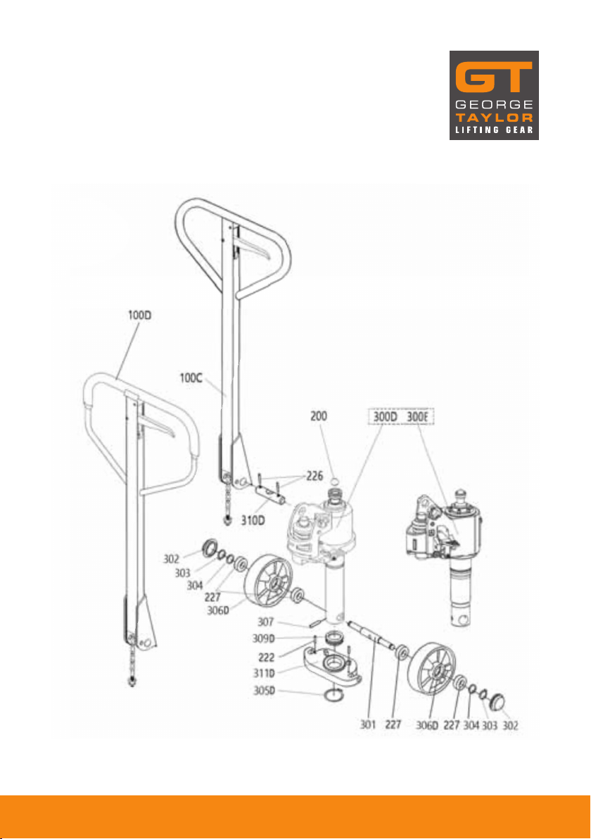
2.
Insert handle pin into
corresponding holes and
using a hammer, drive in one
spring pin on one side only.
3.
Insert handle pin without the
handle and verify that the
centre hole is facing you.
4.
If handle pin’s centre hole is
facing away from you, insert
pin from other side
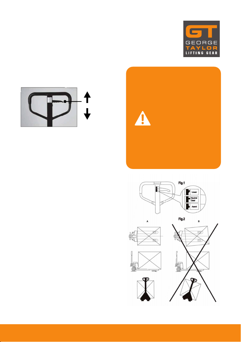
IMPORTANT
The up/down lever’s chain
passes through this centre
hole. If left this way, the
chain will have an “S” form
and be under too much
tension, maing the up/
down lever difficult to use
accurately.
5.
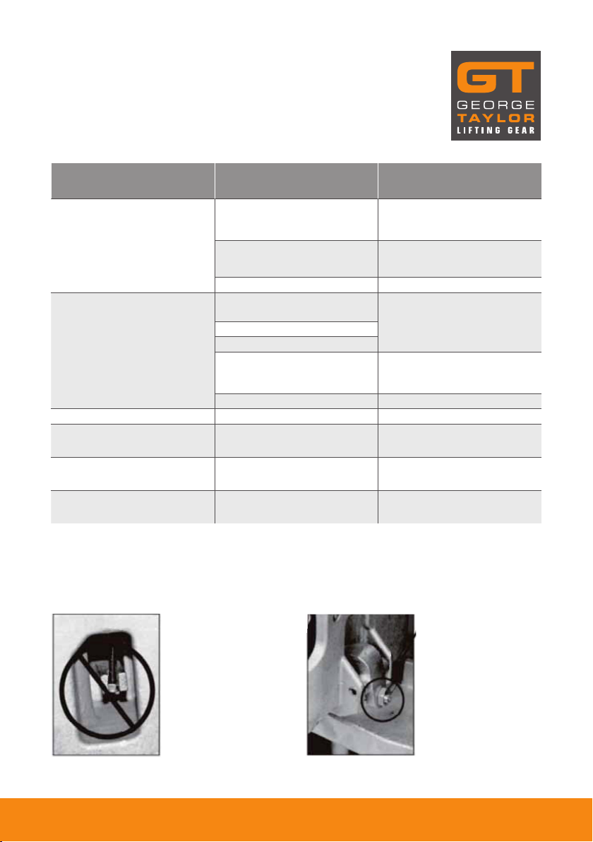
IMPORTANT
Before this step, make sure
to feed the chain on the
outside of the piston stem
roller (see arrow). If left in its
proper position, it will not be
possible to insert the handle
pin and chain, breakage may
occur. Align handle holes
with pump housing holes and
push through handle pin
(see arrow).
6.
Make sure that the handle
pin is completely through the
handle and resting on the
other side.


 Operator's manual")


