Gtec NS3000 10 kVA User manual

-1-
NS3000 Series User ManualRev. 01
UPS NS3000 10-20-30kVA
USER Manual
-2-
NS3000 Series User ManualRev. 01

-3-
NS3000 Series User ManualRev. 01
SafetyPrecautions
This manual isaboutthe installation and operation ofNS3000 SeriesUPS (Hereinafter referred to
as UPS).
Please carefully read this manualpriortoinstallation.
The UPS must be debugged and maintained by the engineer commissioned by the manufacturer or
the agent.Otherwise, human safetymay be endangered and the damage ofUPS shallnot belong to the
warrantyscope.
UPS isonlyused forcommercial /industrial purpose and cannotbe used aspowerof lifesupport
equipment.
APPLICABLE STANDARDS
This productcomplieswith 2006/95/EC - CE 73/23 & 93/68 (lowvoltage safety) and 2004/108/EC
89/336 (EMC), and EMC standards ofAustralia and NewZealand (C-Tick) , and the following UPS
product standards:
*IEC62040-1-1-Generaland safetyrequirements for use in operator access area
*IEC/EN62040-2 EMC requirements CLASS C3
*IEC62040-3 Performance requirementsand test methods
Continued compliance requires installation in accordance with theseinstructionsand the use of
manufacturer approved accessoriesonly.
WARNING- High earth leakage current
Earth connection is critical before connecting the inputsupply(include both utility supplyand
battery) . Thisequipment must be earthed inaccordance with localelectricalauthoritycodes of
practice.
Earthleakage current exceeds 3.5 mA and islessthan 1000 mA.
Transientand steady-state earth leakage currents,which may occurwhen starting the equipment,
should be taken into account when selecting instantaneous RCCB or RCD devices.
ResidualCurrent Circuit Breakers( RCCBs) must be selected insensitive to DC unidirectionalpulses
(class A ) and transient current pulses ( RCCBs) .
Note it that the earth leakage currents of the load willalso flow acrossUPS RCCB orRCD.
Warning: Back feed Protection
Backfeed protection,(optional), isprovided toisolatethe staticswitchif excessive voltageispresentat the
bypass input whenthe bypass source isdeenergized. If thisfunctionisnot installed andenabled ,there must be
awarninglabelonthe externalbypass switchtoremindthe operator ofthe connection.Thewarningonlabel
shouldbe: Isolatethe UPS beforeoperating this part.
-4-
NS3000 Series User ManualRev. 01
Componentsthat can be maintained by user
All the equipment maintenance and servicing procedures involving internalaccess need special tools
and should be carried out only by trained personnel.The components that can only be accessed by
opening the protective cover with tools cannot be maintained by user.
This UPS full complieswith“IEC62040-1-1-Generaland safety requirements for use in operator
access area UPS”.Dangerousvoltages are presentwithin the battery box. However, the risk of
contact with these high voltages isminimized for non-service personnel. Since the component with
dangerous voltage can onlybe touched by opening the protective coverwith a tool, the possibilityof
touching high voltage component is minimized. No riskexists to any personnelwhen operating the
equipment in the normalmanner,following the recommended operating proceduresin thismanual.
BatteryVoltage Higher Than 400Vdc
All the battery maintenance and servicing procedures involving internalaccessneed specialtools or
keys and should be carried outonly by trained personnel.
SPECIAL CARE SHOULDBE TAKEN WHEN WORKING WITHTHE BATTERIES ASSOCIATED
WITH THIS EQUIPMENT. WHEN CONNECTED TOGETHER, THE BATTERY TERMINAL
VOLTAGE WILL EXCEED400Vdc AND IS POTENTIALLY LEATHAL.
Battery manufacturerssupply detailsof the necessary precautionsto be observed when working on,
orin the vicinityof, a large bank of battery cells.These precautions should be followed implicitly at all
times. Particular attention should be paid to the recommendationsconcerning localenvironmental
conditionsand the provision ofprotectiveclothing, firstaidand fire-fighting facilities.

-5-
CONTENTS
Chapter 1 Quick Start..................................................................................8
1.1 Introduction...................................................................................................................................................8
1.2 InitialChecking..............................................................................................................................................8
1.3 EnvironmentChecking...................................................................................................................................8
1.4 InstallationChecking......................................................................................................................................8
Chapter 2 Installation Guidance...................................................................9
2.1 Introduction...................................................................................................................................................9
2.2.2 BatteryRoom................................................................................................................................10
2.2.3 Storing..........................................................................................................................................10
2.3 Disassembly, InitialCheckingandPositioning..............................................................................................10
2.3.1 SystemPacking.............................................................................................................................10
2.3.1.1 Remove the ups fromthe pallet.................................................................................................11
Fig 2-1 UPS Packing Diagram...................................................................11
2.3.2 UPS Composition..........................................................................................................................12
2.3.3 OperationSpace............................................................................................................................12
2.3.4 FrontandBack Access...................................................................................................................12
2.3.5 FinalPositioning...........................................................................................................................12
2.3.6 Cable Entry...................................................................................................................................12
2.4 Protective Devices........................................................................................................................................12
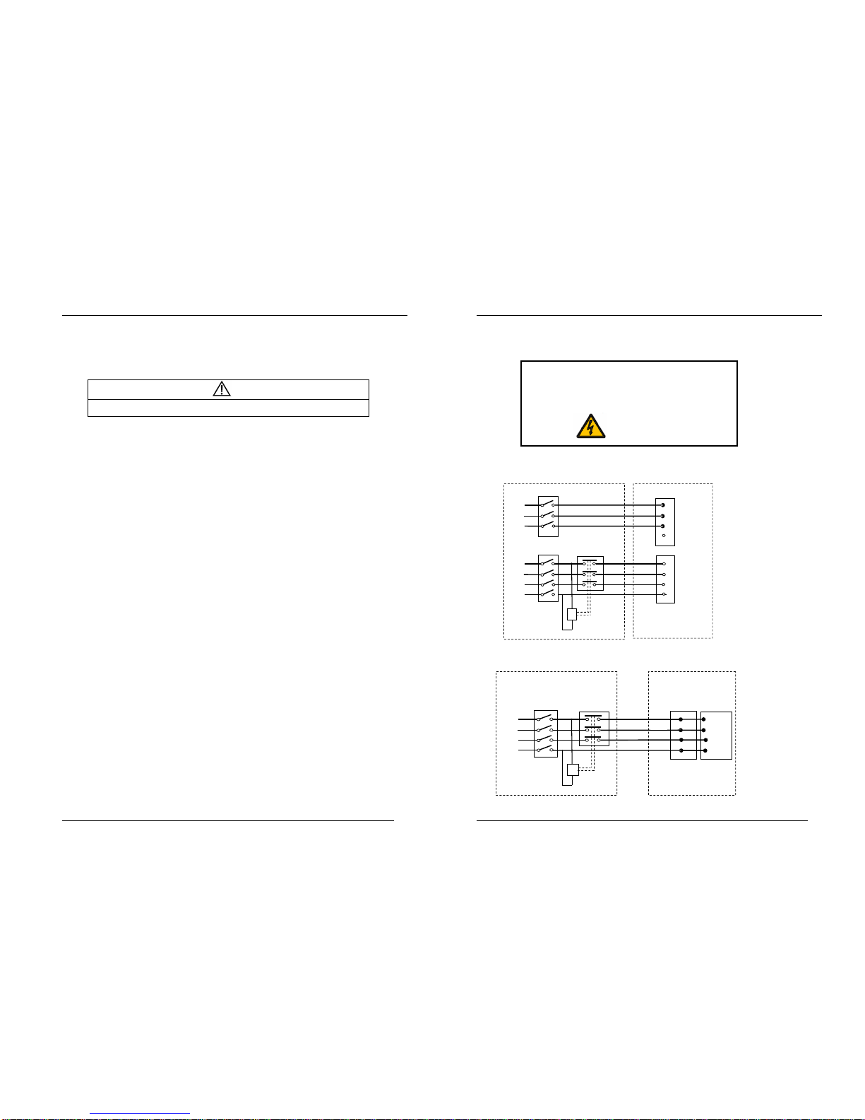
2.4.1.1 Rectifier andBypass InputSupplyofthe UPS.............................................................................13
2.4.1.2 Beakfeed Protection.................................................................................................................14
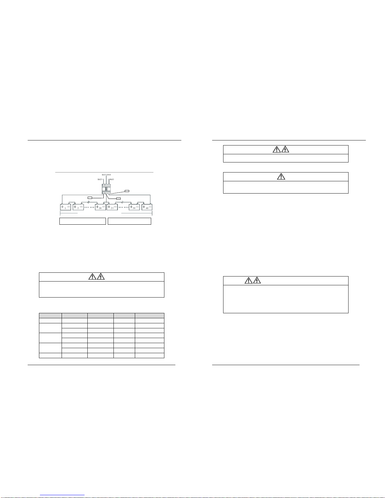
2.4.3 Battery..........................................................................................................................................15
2.4.3 UPS Output...................................................................................................................................15
2.5 Power Cables...............................................................................................................................................15
2.5.1 Maximumstablestate currentand configurationofminimumcable system.....................................15
2.5.2 Cable Connection..........................................................................................................................16
2.5.3 Connectionfor Battery...................................................................................................................17
2.6 ControlandCommunicationCabling............................................................................................................20
2.6.1 DryContactInterface of BatteryandEnvironmentalTemperatureDetection(Optional)...................20
2.6.2 RemoteEPOInput Port(Optional).................................................................................................21
2.6.3 Generator Input DryContact(Optional).........................................................................................22
2.6.4 BCBInterface (Optional)...............................................................................................................22
2.6.5 BatteryWarningOutputDryContact Interface (Optional)...............................................................23
2.6.6 GeneralWarningOutputDryContactInterface (Optional)..............................................................23
2.6.7 Mains FailureWarning OutputDryContact(Optional)...................................................................24
2.6.8 RS232-RS485PortandSNMP Card Port.......................................................................................24
2.7 InstallationDiagram..................................................................................................................................25
Chapter 3 Operations................................................................................27
3.1 Introduction.................................................................................................................................................27
3.1.1 Principle........................................................................................................................................27
3.1.2 Bypass..........................................................................................................................................28
3.1.3 BatteryTemperatureCompensation...............................................................................................28
3.2 OperationMode...........................................................................................................................................28
3.2.1 NormalMode................................................................................................................................29
3.2.2 BatteryMode................................................................................................................................29
-6-
NS3000 Series User Manualrev.01
3.2.3 Auto-RestartMode........................................................................................................................29
3.2.4 Bypass Mode.................................................................................................................................29
3.2.5 Maintenance Mode........................................................................................................................29
3.2.6 ECOMode....................................................................................................................................29
3.2.7 FrequencyConverters Mode..........................................................................................................29
3.2.8 Parallelconnectionredundancymode.............................................................................................30
3.3 BatteryManagement....................................................................................................................................30
3.3.1 NormalFunction...........................................................................................................................30
3.3.2 Advanced Functions (BatterySelf-checking andMaintenance).......................................................30
3.4 BatteryProtection........................................................................................................................................30
Chapter 4 Installation of Parallel Operation System....................................31
Chapter 5 Operating Procedures................................................................33
5.1 Power Switches............................................................................................................................................33
5.2 UPS Start-up................................................................................................................................................33
5.2.1 NormalModeStart........................................................................................................................33
5.2.2 BatteryModuleStart Only Applicablefor theUPS withBatteryCold StartElements)..............35
5.3 Procedure for Switching betweenOperationModes.......................................................................................35
5.3.1 Procedure for Switching the UPS intoBatteryfromNormalMode..................................................35
5.3.2 Procedure for Switching the UPS intoBypass fromNormalMode..................................................35
5.3.3 Procedure for Switching the UPS intoNormalfromBypass Mode..................................................36
5.3.4 Procedure for Switching the UPS intoaMaintenance Bypass fromNormalMode...........................36
5.3.5 Procedure for Switching the UPS intoNormalfroma Maintenance Bypass Mode...........................36
5.4 Procedure for CompletelyPowering downa UPS..........................................................................................36
5.5 EPOProcedure.............................................................................................................................................37
5.6 LanguageSelection......................................................................................................................................37
5.7 ControlPassword.........................................................................................................................................37
Chapter 6 Operator Control and Display Panel...........................................38
6.1 Introduction.................................................................................................................................................38
6.1.1 LEDIndicator...............................................................................................................................39
6.1.2 Audible Alarm(buzzer).................................................................................................................39
6.1.3 FunctionalKeys............................................................................................................................40
6.2 LCDDisplayType.......................................................................................................................................40
6.2.1 DefaultDisplay.............................................................................................................................40
6.2.2 DataDisplay..................................................................................................................................40
6.2.3 Setting Display..............................................................................................................................41
6.2.4 FunctionDisplay...........................................................................................................................41
6.2.5 StateDisplay.................................................................................................................................41
6.2.6 ConfirmDisplay............................................................................................................................42
6.2.7 HistoryRecordDisplay..................................................................................................................42
6.3 DetailedDescriptionofMenu Items..............................................................................................................43
6.4 AlarmList...................................................................................................................................................44
Chapter 7 Maintenance..............................................................................45
7.1 Instructionof Maintenance Operation...........................................................................................................45
7.1.1 Precautions....................................................................................................................................45
7.1.2 Instructionto Bypass Module.........................................................................................................45
Chapter 8 Product Specification.................................................................46
8.1 Applicable Standards....................................................................................................................................46

-7-
NS3000 Series User Manualrev.01
8.2 EnvironmentalCharacteristics......................................................................................................................46
Table 8-2...........................................................................................................................................................46
8.3 MechanicalCharacteristics...........................................................................................................................46
8.4 ElectricalCharacteristics (InputRectifier).....................................................................................................47
8.5 ElectricalCharacteristics (IntermediateDCLink)..........................................................................................47
8.6 ElectricalCharacteristics (Inverter Output)....................................................................................................48
8.7 ElectricalCharacteristics(Bypass Mains Input)..............................................................................................49
8.8 Efficiency....................................................................................................................................................49
-8-
NS3000 Series User Manualrev.01
Chapter 1QuickStart
1.1 Introduction
This chapterintroduces the basicprinciples for UPS installation and debugging, sothat personal service can install
and debug UPS quickly.
1.2 Initial Checking
Performthe following checking operations prior to the UPS installation.
1. Visually examine ifthere is any damp, water,or damage inside and outside the UPS packing, products and battery
equipments due to the transportation. Report any such damage to the shipperimmediately.
2. Verify the product label and confirmthe correctness of the equipment. The equipment label is attached on the panel
behind front door. The UPS model,capacityand mainparametersare marked on the label.
3. Verify correctnessof the accessories. If there is any mistake foraccessories, contact with shipperor provider.
1.3 Environment Checking
Beforeinstalling UPS, pleasechecktheseitems as below:
1. Is the UPS operation environment temperature above 25°C? If so,please add cooling equipments.
Note: Environment temperature above 20°C,battery life will reduce to half when environment temperature
rise each 10°C.
2. Is the UPS operation environment temperature below0°C? If so, please add heaters.
3. Is the UPS operation environment humidityisabove 90% Is thereany condensing? If so, pleaseadd additional
protection.
4. In the UPS operation environment, isthere any sunshine shining in directlyor life-formcoming in? Ifso,pleaseadd
additionalprotection.
5. In the UPS operation environment, isthere any dust,combustible orexplosivegas? If so, pleaseadd additional
protection.
1.4 Installation Checking
After finishing installation,please checkthese itemsas below:
1. Is UPS installed on the flame-retardant materials?
2. Are allcables connected exactly?
3. Are allgrounded systemconnected according to the manual?
4. Is there enough operation space around UPS?
5. Please confirmallUPS external terminalsare fastened, the moment should meet requirements.
6. Please confirmthat there are no screws, cables and other conductorleft in the UPS. If there is,please take out.

-9-
NS3000 Series User Manualrev.01
Chapter 2InstallationGuidance
2.1 Introduction
This chapter introduces UPS installation, itprovide normalinstallation stepsand ideas. Please installation engineers
operate according to each place difference,
Warning-Installation canonlybedone by authorizedengineers
1. Do not apply electrical powerto the UPS equipmentbefore the approvalof commissioning
engineer.
2. The UPS should be installed bya qualified engineer in accordance with the information contained
in this chapter.
Note: 3-Phase 4-Wire Input Power is required
The standard UPS can be connected to TN, TT AC distribution system(IEC60364-3) of 3-phase
5-wire.For ITsystempleasecontact us.
WARNING: batteryhazards
SPECIAL CARE SHOULD BE TAKEN WHEN WORKING WITHTHE BATTERIES ASSOCIATED
WITH THIS EQUIPMENT. When connecting the battery, the battery terminalvoltage will exceed
400Vdc and is potentiallylethal.
lEye protection should be worn to prevent injury fromaccidentalelectricalarcs.
lRemove rings, watchesand all metalobjects.
lOnly use tools withinsulated handles.
lWear rubber gloves.
lIf a battery leaks electrolyte, or is otherwise physicallydamaged, itmust be replaced,stored in a
container resistant to sulfuric acid and disposed of in accordance with local regulations.
lIf electrolyte comes into contact with the skin, the affected area should be washed immediately
with water.
2.2.1DistributionRoom
The UPSisdesigned for indoor installation, whichshall be located in aclean environment with adequate ventilation
to keep the environmentaltemperature withinthe required specification.The UPS uses forced convection cooling by
internalfans. Cooling air enters the modulethrough ventilation grillslocated at the front part or infront and botton
(NS3030) of the cabinet and exhausted through grillslocated inthe rear partof the cabinet. Please do not block the
ventilation holes.
If necessary,asystemof extractor fans shouldbe installed to aidcooling-air flow.Anair filter should be used when
the UPS is to operate ina dirty environment and should be regularlycleaned to maintain airflow.
Note: The UPS should be installed on a cement surface or other surface thatis notcombustible.
-10-
NS3000 Series User Manualrev.01
2.2.2BatteryRoom
The batterywillgeneratesome amount of hydrogen and oxygen at the end of charging, so the fresh air volumeof
the batteryinstallation environment must meet EN50272-2001 requirements. The ambient temperature of the battery
must be stable. Ambienttemperature is a major factor in determining the battery capacity and life. The nominaloperating
temperature ofbattery is20°C. Operating above thistemperature willreduce the batterylife, and operation belowthis
temperature will reducethe battery capacity.If the average operating temperature of batteryis increased from20 Cto
30 C, then the service life of the battery will be reduced by 50%. If the operating temperature of the batteryisabove 40 C,
then the batteryservice life willbe decreased in exponent rate. In anormalinstallation, the battery temperature is
maintained between 15°C and 25°C. Keep batteries awayfrom heat sources or air outlets.
If externalbatteriesare tobe used, abattery protection device (a DCcircuit breaker) must be mounted as close as
possible to the batteries,and the connecting cables should be as short aspossible.
2.2.3Storing
If the equipment not be installed immediately,it mustbe stored inaroomso as toprotectitagainst excessive
humidityand heat sources.The battery needs to be stored indry and cool place with good ventilation. The mostsuitable
storage temperature is20 C to 25 C.
2.3 Disassembly, Initial Checking and Positioning
Checkthe packaging first upon the arrivalof productto see if thereis any damage; open the packaging to check the
equipment; report any such damage to the shipper immediately.
2.3.1SystemPacking
Remove the carton boxand the plasticfilmfirst, thensee.Durigthe procedure under descript Be careful not
scratch the product.

-11-
NS3000 Series User Manualrev.01
REMOVING THEUPS FROM THE PALLET
Fig 2-1 UPS PackingDiagram
CAUTION!TOAVOIDHARMING PEOPLEAND/OR DAMAGING THE EQUIPMENT,FOLLOW
CAREFULLYTHE FOLLOWING INSTRUCTIONS.
SOME OF THESE INSTRUCTIONS NEED TO BE CARRIED OUTBY TWO PEOPLE.
Cut the straps andremovethecardboard box by
sliding it upwards. §Removethe2brackets securingthe UPStothepalletbyunscrewingthe
screws.
§Thepreviouslyremoved brackets can alsobe usedas slides. Secure the slides tothe pallet byusing the type Ascrews, makingsure
theyare aligned with thewheels.
§Screw thebrakerod completely, so toseparate it from thepallet
§Make surethat thedooris firmlyclosed.
§CAUTION! Push the UPSfrom the rear withgreat care. Given the weight of the equipment, thisoperationneedsto becarried out
by two peopleNOTE :It is recommended to keep all parts of the packaging for further use
Tip: Dismantle thebolts that connect thecabinet and wooden pallet afterdisassembly, then lift thecabinet toinstallationposition. The
dismantlement should becarefulsoas not toscratchthe body.
-12-
NS3000 Series User Manualrev.01
Verifythe product label and confirmthe correctnessof the equipment. The equipment labelisattached on the back
of front door.The UPS model,capacity and main parameters are marked on the label.
Warm Tips: Please dispose thewasted materials in accordance with environmental protection requirements
after disassembly.
To prolong the servicelife, the place chosen forthe UPS must guarantee:
lEasy wiring
lSufficient space for operation
lAir sufficient enough to dispelheat produced by UPS
lAgainst ambient corrosive gases
lAgainst excessive humidityand heatsources
lAgainst dust
lWith the current fire prevention requirements
lThe operating environment temperature iswithin20 -25 .The batteries are at maximumefficiency inthis
temperature range (for information about the battery storage and transportation as wellas the environment, please
referto table 8-2)
2.3.2UPS Composition
10KVA~30KVAcabinet
2.3.3Operation Space
As UPS has no ventilation grillsat eitherside, no clearances are required for the sides.
To enable routine tightening of power terminationswithin the cabinet,itis recommended that clearancearound the
front and back of the equipment shouldbe sufficient to enablefree passage of personnelwiththe doors fully opened.
The backdoor of the cabinet is more than 800mmfromthe wallorothercabinets.
Distance fromthe back ≥200mm
2.3.4Front and Back Access
The component layout of the UPS supportsfront and back accessfor servicing, diagnosing and repairing the UPS,
thus reducing the space requirement for side access.
2.3.5FinalPositioning
When the equipment has been finallypositioned, ensurethe adjustablefeetisset sothat the UPS willremain
stationary and stable.
2.3.6CableEntry
Alower incoming line isused for 10KVA~30KVAUPS.
2.4 Protective Devices
Forsafety concerns, itisrecommended to install externalcircuitbreakers or other protectivedevices for the input
AC supply of the UPS system.
Wesuggest tochoose the input automatic break Biggerthan internalautomaticBreaker and Dcurvefor the selectivity
with internalUPS protection.
Thissection provides genericpracticalinformation for qualified installation engineers.The installation engineers
should have the knowledge of the regulatory wiring standards, and of the equipment to be installed.

-13-
NS3000 Series User Manualrev.01
2.4.1.1Rectifier and BypassInput Supply ofthe UPS
Install suitableprotectivedevicesinthe distribution unitof the incoming mains supply,considering the power cable
current-carrying capacityand overload capacity of the system.Generally,the magneticcircuitbreaker with IEC60947-2
tripping curve C (normal) atthe 125%of the current listed in table2-1 is recommended. Whith common input we suggest
tripping curve d
Note
For IT powernetwork system, 4-poleprotective devicemust be installedonthe external input distribution of the
UPS.
Earth leakage current
If protection againstearth faults(RCD devices) is required for the upstreamof the inputsupply,the installed device
should:
lSensitive to DC Class B orclass A in the network
lInsensitive to transient current pulses
lHave an average sensitivitythat is adjustable between 0.3A-1A
-14-
NS3000 Series User Manualrev.01
2.4.1.2Backfeed Protection.
Put a labelon all primary power isolators installed remote fromthe UPS area. One labelis supply
Before working on this circuit
- Isolate UninterruptiblePower System (UPS)
-Then check for Hazardous Voltagebetween all terminals
includingtheprotectiveearth
RiskofVoltage Backfeed
UPS whit by-pass andlineinput separate
UPS whit by-pass andline input common
Payattention Neutralis common point inside UPS.
L11
L21
L31
N1
Q
UPS
Byp
.
terminal
T1
L1
L2
L1ma
N
L3
L2 mb
L3mc
N
Q
Imput terminal
Customer distribution
L1 ba
L2 bb
L3bc
N
L11
L21
L31
N1
Q
UPS
UPS Input
teminal
s
T1
L1ma
L2mb
L3mc
N
Customer distribution
L1ba
L2
L3bc
N

-15-
NS3000 Series User Manualrev.01
2.4.3Battery
Abattery string iscomposed of 40 batteries connected in series, maximum ispossible install2 strings 40batteries (B1-B2
in thisdocument).The positive, the negative and middlepoint (the joint part between the 20th and 21st battery) cable
must push through a DC circuit breaker before connecting to corresponding UPS . For detailed wiring please refers to fig
2-4 below:
Fig 2-4Diagram of batteries connected in series
2.4.3UPS Output
Amain output switch has been installed in UPS; the user shallinstallthe overcurrent protective device on the bypass
and on each output ofthe externaldistribution cabinet.
2.5 Power Cables
Design the cables according to the descriptions inthis section and localregulatorywiring standards,and the
environmentalconditions should be taken into consideration.Refer to IEC60950-1 table 3B.
Warning
Prior cabling the UPS, confirm the statusand positionsof the switchesof the UPS rectifierinput
power supply /bypasspower supplyand mains power distribution board.
Ensure thatthese switches are opened and attached with WARNING label so as to prevent
unauthorized operation to these switches.
2.5.1Maximum stable state current and configuration ofminimum cable system
Table 2-1
ModelName NS3010 NS3020 NS3030
UPS Power 10KVA20KVA30KVA
Rated current A15A 30A 45AMain Input
Cable mm24610
Rated current A15A 30A 45AOutput
Cable mm24610
Rated current A18A 36A 53ABattery
Cable mm2610 16
PE Cable mm2410 10
F
ortybatteriesinseries connection in total
Ba
tt +
Bat
t
-
Batt
-
N
Batt +
Batt
-
B1 + series B1 - series
-16-
NS3000 Series User Manualrev.01
Warning
FAILURE TO FOLLOWADEQUATE EARTHING PROCEDURES CAN RESULT IN EMI, ELECTRIC
SHOCK HAZARD OR RISK OFFIRE,SHOULD AN EARTHFAULT OCCUR.
2.5.2CableConnection
Important
The operationsdescribed in this section must be performed by authorized electricians orqualified
technicalpersonnel.. If you have anydifficulties, do not hesitate to contactour Customer Service &
Support department.
After the equipment has been finally positioned and secured, connect the power cablesas described inthe following
procedures:
1. Verify that allthe externalinput distribution switchesof the UPS are completelyopened (off position) and the UPS
internalmaintenancebypass switch isopened. Attach necessary warning signs tothese switches toprevent
unauthorized operation.
2. Open the door ofthe cabinet, remove the left bottomcover and then the input and output terminal,batteryterminal
and earth terminal are visible.
3. Connectthe inputearth wire toinput earth terminal.Pleasenote:the earth wire shallbe connected inaccordance
with related local orstate regulation
4. Ifin UPS,sameelectricsupply inputis used for the by-pass and maininput AC inputcables should be connected
with the input terminalofUPS (Maininput L1ma–L2mb–L3mc andtheoutputloadcables areconnected
with the output terminal ofUPS (Output L1oa - L2oA -L3oC). If inUPS, twoelectric supply inputs are used for
the rectifierand by-pass, the AC input cables should be respectively connected with the main input terminalof UPS
(Main input L1ma-L2mb – L3mc and the input terminalof the bypass,L1ba,L2bb,L3bc and the short circuit
copper bars betweenthemain circuit and thebypass havetobe removed;fastening moment offorce is
30kg(M5),50kg(M6),180kg(M8). Attention is given to phase sequence and the short circuit at a joint between cable
terminals. If the phase sequence is wrong UPS show an alarm
5. Connect the batterycables between the UPS batteryterminals and battery switch. ENSURECORRECTPolarity.
Warning-Hazardous battery terminalvoltage ≥400Vdc
The operationsdescribed in this section must be performed by authorized electricians orqualified
technicalpersonnel.
Ensure the correct polarity connection between the battery terminalsand the UPS terminals: Positive
terminalto positive terminal, negative terminal to negative terminal,The middlepoin of the batteies is
Neutralpoint in the UPS.
Disconnect inthe tray 1 and tray 5 the cable marked A and B. Do not connect the cables and close
the batterycircuit breakers before getting the approvalfromthe commissioning engineer.
6. Re-installall the protective covers.

-17-
NS3000 Series User Manualrev.01
2.5.3Connection for Battery
On NS3000 10-30kVA series UPS, there isan internal battery breaker in the UPS. Also,thistype UPS offer external
battery connection terminals.If customers want to use externalbattery,they have toinstallabattery breaker or fuse
between the UPS and the externalbattery.
UPS can have one ore twostring of batteries B1 or B1+B2 each string iscomposed with 20+20 Battery with common
point see table1.
UPS B1 B1+B2
NS3010 40*7 or9A/h 2*40*7 or 9A/h
NS3020 40*7 or9A/h 2*40*7 or 9A/h
NS3030 ---------- 2*40*7 or 9A/h
Tab.1
The method ofbuild-in battery connection as shown fig. 2-5:
Warning-Hazardous battery terminalvoltage ≥400Vdc
THE BATTERIES MUST BE INSTALLED WITH THE ORIGINAL MANUFACTORY KIT THAT
INCLUDE THE DEDICATE PLASTIC BATTERY BOX.
KIT CABLE cod. KITNS-CAVBATINT
USE THE MANUFACTORY INSTRUCTION.
2.5.3.1 UPS arrives with out batteriesInstructionsfor fortybatteries
1) Opend the batterybreaker
2) Insert the batteries in the plastic boxand connect the batteries according fig. 2.5.B
3) Checkwiththe multimeter the battery output cablecorrect polarity and voltage (8battery have tobe about
101-104V, 4 batteryave to be about 50-52V)
4) Fixthe plastic batteryboxwith hard tape at least in2 positions.
5) Insert the plastic batteryboxaccording fig. 2.5.A. Payattention all cable are marked and have different color.
6) Connect the batteryaccording fig 2.5.A, don’t connectAand B cablein the shelf1
7) In shelf 1 on the left connect the cable mark Awith the cablemark Bon shelf 2
8) CheckB1- negative battery voltage on battery breaker.Negativebattery is on the batterybreaker rightlower
terminal,the neutralis on the batterybreakercentral lower terminal.
9) With 20 batteriesthe voltage is NEGATIVE, about - 255 /-260V
10) In the shelf 1 (B1+) on the right connect the cablemark Awith the cable mark Bon shelf 2
11) CheckB1+ positive battery voltage on battery breaker.Positive batteryison the batterybreaker leftlower
terminal,the neutralis on the batterybreakercentral lower terminal.
12) With 20 batteriesthe voltage is POSITIVE about + 255 -260V
Impotant: with 80 batteries repeat the operation upper descript change layer1 withlayer 5and B1 with B2 ,with
B1 battery block don’t connect
2.5.3.2 UPS arrived with batteries inside
Startfrompoint 6 to to 2.5.3.1 UPS arrives with out batteries section.
-18-
NS3000 Series User Manualrev.01
Legend fig. 2.5A
B1 first string 40 battery with common point
B2 Second string 40 batteries with common point
BAT – MarkNEGATIVE cable 40 battery seriesoutput
BAT+Markon POSITIVE cable 40 batteryseries output
BATT -.NCommon point 40 batteries series
CBatteries cable
AMarkon positive cable out put 8 or4 seriesbatteries
BMarkon negative out put 8 or4 series batteries
FIG.2.5.AFRONT VIEW AND BATTERY CONNECTION

-19-
NS3000 Series User Manualrev.01
TOPVIEW INTENAL SHELF BATTERY POSITION
I
FIG.2.5.B
-20-
NS3000 Series User Manualrev.01
2.6 Control and Communication Cabling
fig. 2-6 shown, the Relay card drycontact interface (J2-J10), communication interface(RS232 interface, 485
interface and SNMP cardinterface) and parallelcard position.
Fig 2-6 Dry contactinterface and communication interface
The UPS acceptsexternalsignalfromzero-voltage (dry) contactsconnected through externaldrycontact terminals
produced and phoenixterminals.Through software programming, these signalsbecome active when thesecontacts
connectto +24V to ground.The cablesconnected to DRY terminalmustbe separated frompower cables. Moreover,
these cables shouldbe double insulated with atypical0.5 to 1.5mm2cross-section area for amaximumconnection
length between 25 and 50 meters.
2.6.1Dry Contact Interface ofBatteryand Environmental Temperature Detection (Optional)
The input dry contact J2and J3 can detect the temperature of batteries and environment respectively,which can be
used inenvironment monitoring and battery temperature compensation 1.
J2 and J3 interfaces diagramare shown in fig 2-7, the description ofinterface is in table 2-2.
J2J3
Fig 2-7 Diagramof J2 and J3 drycontact for temperature detecting
Table 2-2
Position Name Purpose
J2.1 TEMP_BATBattery temperature detection
J2.2 GND Power ground
J3.1 TEMP_ENV Environment temperature detection
J3.2 GND Power ground
Note:
Specified temperaturesensor isrequired for temperaturedetection (R25=5kOhm,B25/50=3275),
please confirmwith the manufacturer,or contact localmaintenance engineers when placing an order.

-21-
NS3000 Series User Manualrev.01
2.6.2RemoteEPOInput Port (Optional)
The UPS has an Emergency Power OFF (EPO) function. Thisfunction can be activated by pressing abutton on the
controlpanelof the UPS or through a remote contact provided by the user. The EPO pushbutton is protected bya hinged
plastic cover.
J4 isthe input port forremoteEPO. It requires shorting NCand +24v during normaloperation, and the EPO is
triggered when opening NC and +24v,orshorting NO and +24v.The port diagramisshowninFig 2-8, and port
description isshown in table 2-3.
J4
+24V
Fig 2-8 Diagram of input portfor remote EPO
Table 2-3 Description of inputport for remote EPO
Position Name Purpose
J4.1 EPO_NC EPO isactivated when disconnecting fromJ4.2
J4.2 +24V +24V, connectthe common terminalof NCand NO
J4.3 EPO_NOEPO is activated when shorting with J4.2
If an external emergencystop facility is required,itisconnected viathe reserved terminalsofJ10.The external
emergencystop facilityneedsto use shielded cablestoconnectto the `normallyopen/closed remote stop switch
between these twopins. Ifthisfacilityis not used,then pin 2and pin 3ofJ4 must be open,or pin 1and pin2ofJ4 must
be shorted.
Note
1.The emergency stop action withinthe UPS willshut down the rectifier, inverter and staticbypass.
However, it doesnot internally disconnect the mainsinput and batterypower supply. To disconnect
ALL power to the UPS, open the upstreaminput circuit breaker(s) and batterybreakerwhen the EPO
is activated.
2.Pin1 and 2 of J4 have been shorted before the UPS isdelivered
-22-
NS3000 Series User Manualrev.01
2.6.3Generator Input Dry Contact(Optional)
J5 isstatusinterfacefor generatorconnection.Connectpin 2of J5 with+ 24V power supply,and it indicates that the
generator has been connected with the system.The interface diagramis showninfig 2-9 and interfacedescription is
shown in table 2-4
Fig2-9 Diagramof status interface and connection of generator
Table 2-4
Position Name Purpose
J5.1 +24V +24V power supply
J5.2 GEN Connection statusof generator
J5.3 GND Powerground
2.6.4BCB Interface (Optional)
J6 andJ7arebatterycircuitbreaker(BCB)interface. The interface diagram is shown in fig 2-10 and interface description
isshown in table 2-5.
BCB_DRV
BCB_CON
T
BCB_ONL
Fig 2-10 BCB Interface
Table 2-5
Position Name Purpose
J6.1 BCB_DRVBCB drive signal: providing +24V, 20mA drive signal
J6.2 BCB_CONTBCB contactstatus,connect to BCB’s normalopen signal
J7.1 GND Power ground
J7.2 BCB_ONL BCB online input normalopen),itshowsBCB is online when this
signalconnects to GND.
Generator

-23-
NS3000 Series User Manualrev.01
2.6.5BatteryWarning Output Dry Contact Interface (Optional)
J8 is the output dry contactinterface,which indicate the batterywarnings of low or excessive voltage,when the
battery voltage islower than set value, an auxiliary dry contact signal will be provided. The interfacediagramis shown in
fig 2-11, and description is shown in table 2-6.
BAT_LOW_NC
BAT_LOW_NO
GND
Fig 2-11 Battery warning dry contact interface diagram
Table 2-6
Position Name Purpose
J8.1 BAT_LOW_NC Batterywarning relay (normallyclosed)willbe open during warning
J8.2 BAT_LOW_NOBatterywarning relay (normallyopen) willbe closed during warning
J8.3 GND Center of battery warning relay common
2.6.6General WarningOutput Dry Contact Interface (Optional)
J9 is the genera warning output dry contact interface, when one or morethan one warning istriggered,the system
willsend integrated warning information, and provide an auxiliary dry.The interfacediagramisshowninfig 2-12, and
description isshown in table 2-7
J9
ALARM_NC
ALARM_NO
GND
Fig 2-12 Generalwarning dry contact interface diagram
Table 2-7
Position Name Purpose
J9.1 ALARM_NC
Integrated warning relay(normallyclosed) will be open during warning
J9.2 ALARM_NO
Integrated warning relay(normallyopen) will be closed during warning
J9.3 GNDCentre of integrated warning relay
-24-
NS3000 Series User Manualrev.01
2.6.7MainsFailure Warning Output Dry Contact(Optional)
J10 isthe output dry contactinterface for mains failure warning, when the mains fails, the systemwill send amains
failure warning information.. The interface diagramisshown in fig 2-13, and description is shown in table 2-8.
Fig2-13 Mains failure warning dry contact diagram
Table 2-8
Position Name Purpose
J10.1 UTI_FAIL_NC
Mainsfailure warning relay(normallyclosed) will be open during warning
J10.2 UTI_FAIL_NO
Mainsfailure warning relay(normallyopen) will be closed during warning
J10.3 GND Centre of mainsfailure warning relaycommon
2.6.8RS232-RS485 Port and SNMP Card Port
RS232 and RS485 Port:provide serialdatawhich can be used for commissioning and maintenance by authorized
engineersor maintainers, or can be used for networking or integrated monitoring systemin the service room.
SNMP Card Port: used for field installation of the communication option card (SNMPcard).

-25-
NS3000 Series User Manualrev.01
2.7 Installation Diagram
-26-
NS3000 Series User Manualrev.01
a. 10KVA~30KVA terminalblock
NS3030
NS3010
NS3020

-27-
NS3000 Series User Manualrev.01
Chapter 3 Operations
Thischapter introduces the basicknowledge of UPS operations,including working principle, operation mode, battery
management and protection.
Warning:Hazardousmainsvoltage and/or batteryvoltage present(s)behind the
protectivecover
1.The components that can only be accessed byopening the protective cover with toolscannot be
operated byuser.
2.Only qualified service personnel are authorized to remove such covers.
3.1 Introduction
UPS provides high qualityuninterruptible AC powerto your criticalload.The powerfromUPS isfree from voltage
and frequencyvariations and disturbances (interruption and spike) experienced at the Mains AC input supply.
Thisis achieved through high frequencydoubleconversion power pulse width modulation (PWM) associated with
full digitalsignal processing control(DSP),which featureshigh reliabilityand convenience for use.
3.1.1 Principle
As showninfig3-1, the AC input mains source issupplied at UPS input and converted into aDC source.ThisDC
sourcefeeds the Inverter thatconvertsthe DC source into a clean and input independentACsource. The battery powers
the load through the inverter incase of an AC input mainspower failure. The utility source can alsopower the load
through the staticbypass.
When the UPS needs maintenanceor repair,the load can be transferred to maintenance bypasswithout interruption
and the powermodule and bypass module can be removed for maintenance.
Fig 3-1 Systemprinciple framework
-28-
NS3000 Series User Manualrev.01
3.1.2 Bypass
. During normalsystemoperation the load isconnected to the inverter; but in the event of a UPS overload or inverter
failure, the load isautomatically transferred to the staticbypass line.
Toprovide aclean (no-break)load transfer between the inverter output and staticbypass line, the inverter output
and bypass supply must be fullysynchronized during normaloperating conditions. This isachieved through the inverter
controlelectronics,which makesthe inverterfrequencytrackthatof the staticbypass supply,provided that the bypass
remains within an acceptable frequency window.
Amanuallycontrolled maintenance bypass supply isincorporated into the UPS design. Itenables the critical load to
be powered fromthe utility(bypass) supply whilethe UPS is shut down for routine maintenance.
Note
When the UPS is operating inbypassmode or on maintenance bypass, the connected equipment is
not protected frompower failures orsurges and sags。
3.1.3 BatteryTemperature Compensation
The UPS can connect temperature sensor whichis inthe battery cabinet to the UPS monitor unit through battery
temperature interface in order to reach battery management optimization.
Fig 3-2 Temperature compensation diagram
3.2 OperationMode
NS3000 isan on-line, double-conversion UPS that permitsoperation in thesemodes:
lNormal mode
lBatterymode
lAuto-Restart mode
lBypassmode
lMaintenancemode (manualbypass)
lECO mode (Settable bys.w.)
lFrequency converters mode (only to request)
lParalleloperation redundancy mode (Optional)

-29-
NS3000 Series User Manualrev.01
3.2.1Normal Mode
The UPSinverter power modules continuously supply the critical AC load. The rectifier/charger derives power from
the AC mains input source and suppliesDC powerto the inverter while simultaneouslyFLOATor BOOSTcharging its
associated backup battery.
3.2.2BatteryMode
Upon failure of the AC mains input power; the inverterpower modules,which obtains power fromthe battery,
supplies the critical AC load. Thereisno interruption inpower to the critical load upon failure. After restoration ofthe AC
mains input power, the “NormalMode” operation willcontinue automatically without the necessity of userintervention.
Note: UPScan also be started through battery mode via battery coldstart function upon failureofthe AC mains.
Therefore, the battery power can be used independently to improve the utilization rate of UPS.
3.2.3 Auto-Restart Mode
The batterymaybecomeexhausted following an extended AC mains failure.The inverter shutsdownwhen the
battery reachesthe End of Discharge voltage (EOD). The UPS may be programmed to “Auto Recovery after EOD”after
a delaytime ifthe AC mainrecovers. Thismode and any delaytime are programmed by the commissioning engineer.
During the process of delay time, the battery will be charged byUPS to prevent any risks to load equipment from
futuremains failure.
3.2.4 Bypass Mode
If the inverter overload capacityisexceeded undernormalmode, or ifthe inverter becomes unavailable forany
reason, the statictransfer switchwill performatransfer of the load fromthe invertertothe bypass source,with no
interruption in power to the critical AC load.
3.2.5 Maintenance Mode
Amanualbypass switchis available to ensure continuity of supplyto the critical load when the UPS becomes
unavailable e.g. during a maintenance procedure.
It isnoticed that after UPS systemsupplies the power with the bypassmode, the maintenance bypass rotary switch
Q3, in thissituation isclosed Q1, Q2,Q3-2 output contacts and battery switches are disconnected.
Warning: Hazard may occurafter transferring to maintenance bypass
After UPS being transferred to maintenance bypass,UPS battery,input and output terminals and are
charged.
3.2.6 ECO Mode
If economical(ECO) mode is selected, the double-conversion UPS willstop to work so as to saveenergy. During the
operation of ECOmode, the load power willbe supplied bybypass preferentially. When bypasspower is within the range
of normalfrequency and voltage, load power willbe supplied bybypass,orthe systemwilltransfer to inverter output,
followed by load power interruption which extendswithin 3/4 ofthe period. E.g.when the frequency is50Hz,the
interruption timewill be less than 15ms; when the frequencyis60Hz, the timewill be less than 12.5ms.
Eco mode have to set bycustomer service
3.2.7FrequencyConvertersMode
If the frequencyconverter configuration isused by UPS,itwill provide 50Hz or 60Hzstable output frequency.The
range of output frequencyis40Hz-70Hz. Underthismode, static bypassisunavailable, but battery can be selected
according to the actual requirements of battery mode.
Frequency Converte Mode have to set bycustomer service
-30-
NS3000 Series User Manualrev.01
3.2.8Parallelconnectionredundancy mode
SeveralUPS devices maybe parallelconnected directlyand the paralleloperation controllogic insingleUPS
devices ensuresallsingledevice automaticallysharethe load to improve the capacityor reliability of the system,orboth
the capacity and reliability of the system.The capacityof a paralleloperation systemcan be up to 6 units.
3.3 BatteryManagement
3.3.1 Normal Function
The following functions should be fitted by commissioning engineers with specified software.
1. Constant current boost charging
Current can be set up
2. Constant voltage boost charging
Voltage ofboost charging can be set asrequired by the type of battery.
For Valve Regulated Lead Acid (VRLA) batteries, maximumboost charge voltage should not exceed 2.4V / cell.
3. Float charge
Voltage offloat charging can be setas required bythe type of battery.
For VRLA, float charge voltage should be between 2.2V to 2.3V.
4. Float charge temperature compensation (optional)
Acoefficient of temperature compensation can be setas required by the type of battery.
5. End of discharge (EOD)protection.
If the batteryvoltage is lower than the EOD, the battery converter willshutdownand the battery isisolated to avoid
further battery discharge. EODis adjustablefrom1.6V to 1.75V per cell(VRLA) or 0.9 to 1.1 V per cell
6. Battery lowwarning time
It is adjustable between 3 and 60 minutes. The defaultis 5 minutes.
3.3.2 Advanced Functions(Battery Self-checkingandMaintenance)
At periodicintervals,20%ofthe rated capacity ofthe battery willbe discharged automatically,and the actual load
must exceed 20% of the rated UPS (KVA) capacity.If the load islessthan 20%,auto-discharge cannot be executed. The
periodicinterval can be set from 30 to 360 days. The battery self-test can be disabled.
Conditions—Battery at float charge forat least 5 hours, load equal to 20~100% of rated UPS capacity
Trigger—Manually through the command of “Battery Maintenance Test” inLCD panelor automatically
3.4 BatteryProtection
The following functions should be fitted by commissioning engineers with specified software.
1. Battery LowPre-warning
The battery undervoltage pre-warning occurs before the end of discharge. After this pre-warning, the batteryshould
have the capacity for 3 remaining minutes discharging with fullload. The time is user configured from3 to 60 minutes.
2. Battery discharge (EOD)off protection
If the battery voltage is lower than the EOD, the battery converter willbe shut down. EOD is adjustablefrom1.6V to
1.75V per cell (VRLA) or 0.9 to 1.1 V per cell (NiCd)
3. BatteryCircuit Breaker (BCB)Alarm(Optional)
The alarmoccurswhen the battery disconnectdevice disconnects. The external battery connectstothe UPS
through the external batterycircuitbreaker.The circuit breakerismanuallyclosed and tripped by the UPS control circuit.
See relay cardoptionals

-31-
Chapter 4Installation ofParallel Operation
System
The paralleloperation system isinstalled asrequired by the installation proceduresof the single
systemand thischapter.
The single devices areput paralleland connected as showninfig. 4-1,and the difference between
the lengths ofthe output cablesof the single devices isnot more than 10m.Itisrecommended touse an
externalbypass cabinet to facilitatemaintenance and system testing.
Fig. 4-1 Typical1+N parallel operation system
Note: when the load exceeds the capacity of the single device, werecommended anexternal
manual Bypass. The cables for the parallel operation provide double insulation shielding up to 30mlong,
the control cablesfor the parallel operation mustbe connected withallsingle devices toformaclosed
loop,as shown in fig.4-2.
Other power supplies
Rectifier
Charger
Inverter
Inverter
Output power supply
Load connected
Mains powerinput,
UPS1
L1, L2, L3, Nterminal
Mains power input,
UPS2
L1, L2, L3, Nterminal
Rectifier
Charger
Q1
Q1
Q2
Q2
Q
3
-
1
Q
3
-
1
Q
3
-
2
Q
3
-
2
-32-
NS3000 SeriesUser Manual rev.01
Fig.4-2 Parallel cables

-33-
NS300 Series User Manual
Chapter5 OperatingProcedures
ThischapterdescribesUPS operation instructions in detail.
All functional keysand LED displayinvolved inoperation instructions please refer to chapter 5.
During operation, the buzzer alarmmay occurat any time. Select“mute”on LCD to muffle the audible
alarm.
Warning-Hazardous mains voltage and/or batteryvoltage present(s)behind the
protective cover
1. The components that can only be accessed by opening the protectivecover with toolscannot be
operated by user.
2. Only qualified service personnelare authorized to remove such covers.
5.1 Power Switches
As showninfig5-1,open the frontdoorofUPS, the power switch isvisible,whichincludes: input
switch, outputswitch and maintenance bypass switch (with anti-misoperation stop plate)
Fig. 5-1 10KVA~30KVAMains switch location drawing
5.2 UPS Start-up
The UPS systemonly has amaintenancebypass isolating switch, and allthe othertransfers are
processed automatically by internalcontrollogics.
5.2.1NormalMode Start
Thisprocedure must be followed when turning on the UPS froma fullypowered down condition. The
operating procedures areas follows:
-34-
NS3000 SeriesUser Manual rev.01
Warning
This procedure results in mains voltage being applied to the UPS outputterminals. If any load
equipment isconnected to the UPS output terminals please check with the load user that itis safe to
apply power. Ifthe load is notready to receive power then ensure that the output switch of external
distribution cabinet is opened.
Warning
Please confirmthat UPS output rotating switch point to UPS, with anti-misoperation stop plate for
rotating switch is fixed well.
1. Close UPS bypass input switch and input switch in turns
The LCDstartsup at this time. The Rectifierindicatorflashes during the startup of rectifier.The
rectifier enters normaloperation state, and afterabout 30s,the rectifierindicator goes steady green. After
initialization, the bypass staticswitch closes. The UPS MimicLEDswillindicate as shown in table 5-1:
Table 5-1 Indicatorstatus
LED Status
Rectifier indicator Green
Batteryindicator Red
Bypassindicator Green
InverterindicatorOff
Load indicator Green
Status indicatorGreen
Warning
The bypassinput air switch must be opened firstly and then the input airswitch is opened, otherwise,
the rectifiercan not be started and the systemcan not control the power.
The inverter startsup at this time,the inverter indicator flashes.After the rectifier enters normal
operation state,UPS power supply willtransfer frombypasstoinverter,then the bypass indicator turns
off, and load indicatorlights.The status of indicatorsisshownin table 5-2
Table5-2 Indicator Status
LED Status
Rectifier indicator Green
Batteryindicator Red
Bypassindicator Off
InverterindicatorGreen
Load indicator Green
Status indicatorGreen
If your UPS is withbuild-in batterytype, please closeinternalbattery DC switch. Battery indicator
turns off, a fewminutes later, the battery will be charged by UPS which willenternormalmode operation.
The indicator statusisshown in table 5-3.
If your UPS is without build-inbattery type, please close externalbattery DC switch.
Warning
Please confirmbattery connection right before closing externalbattery switch.

-35-
NS3000 SeriesUser Manual rev.01
Table 5-3 Indicator status
LED Status
Rectifier indicator Green
Batteryindicator Green
Bypassindicator Off
InverterindicatorGreen
Load indicator Green
5.2.2Battery ModuleStart Only Applicablefor the UPS withBattery Cold Start Elements
)
1. Check if the batteries have been connected, close the externalbattery switch.
2. Pressthe red start-up button of battery on the backdoor panel.
3. The LCD startsup at thistime, pressbattery cold startagainforabout 5seconds. The green battery
indicatorflashes. The rectifier enters normaloperation statesand after about 30s,the battery indicator
goessteady green.
4. The inverter startsup automatically,the green inverter indicator flashes. The inverter will outputafter
60s. Then UPS run inbatterymode.
b. 10KVA~30KVA
Fig. 5-2 diagrammatic drawing forbattery starting button location
5.3 Procedurefor Switching between OperationModes
5.3.1Procedure for Switching the UPSinto Battery from NormalMode
Open inputswitch to cut off the mains,UPS entersthe battery mode. If UPS shouldbe switched to
normalmode, waitfor afewsecondsbefore closing input switch,so as to supplythe mains again.10s
later, the rectifier will start up automaticallyto supply power to the inverter.
5.3.2Procedure for Switching the UPSinto Bypassfrom Normal Mode
Select the manualbypassmenu of "function 1” of “function/ setting”
Note
In bypass mode, the load is directlyfed by the mains power instead ofthe pure AC power fromthe
inverter.
-36-
NS3000 SeriesUser Manual rev.01
5.3.3Procedure for Switching the UPSinto Normal from BypassMode
Select“exitbypassmode” on the LCD,about3secondslater, UPS transfer to inverter mode
automatically.
5.3.4Procedure for Switching the UPSinto a Maintenance Bypass from Normal Mode
In normal operation, thisoperation instruction will switch the load frominverted inputtomaintenance
bypass.
Caution
Before making this operation,read messages on display to be sure that bypass supplyisregular and
the inverter is synchronous withit, so as not to risk a shortinterruption in powering the load.
1. Switch UPS fromnormal mode to bypassmode according to 5.3.2.
The inverter indicator and status indicator go off, the buzzer alarms.The load willbe transferred to
static bypass, and the inverter is closed.
2. Removeanti-misoperation stop plate for rotaryair switch,then the rotary airswitch is switched to the
maintenancebypass side in order that the load power supply issupplied bythe maintenance bypassQ3,
and the mains switch Q1, the bypass switch Q2, the output switch Q3-2and the internal and external
battery switches aredisconnected.
Warning
If it is required tomainten the modules, the cabinet is opened for internalmaitenance afterwaiting for
5minutes in order that the capacitor voltage in the internalDC busautomaticallydischages.
5.3.5Procedure for Switching the UPSinto Normal from a Maintenance BypassMode
Thisprocedure can transfer the load to normalmainmode when the UPS isoperating under the
maintenance bypass mode.
1. Close the bypass switch Q2 and switch the rotaryswitch to “UPS output” side.
The indicator light of the bypass becomegreen and the power issupplied for the load by the
bypass.
2. Close the mains input air switch Q1
The power is supplied for the load by the bypass. Atthe same time, the rectifier begins to operate,
the indicator light of the rectifier becomegreen after 30 seconds,and the power isautomatically
supplied with the inverter after 2 minutes.
3. Closeinternaland external battery switches. If the indicator light ofthe battery does not work,
please confirmthe voltage of the LCD display battery is normal.
4. Replace the anti-misoperation stop plate for rotary switch.
5.4 Procedurefor CompletelyPowering down a UPS
If you need topowerdown the UPS completely,followthe proceduresin section 5.3.4 to transfer the
UPS fromnormalmode to maintenance bypassmode.
If you need to isolate the UPS fromthe ACpowersupply,you should open the external input switch.

-37-
NS3000 SeriesUser Manual rev.01
5.5 EPO Procedure
The EPObutton on UPS operatorcontroland displaypanelisdesigned toswitchoffthe UPS in
emergency conditions (e.g.,fire, flood, etc.).Toachievethis, just pressthe EPO button,and the system
will turn offthe rectifier,inverter and stop powering the load immediately (including the inverter and
bypassoutput), and the batterystops charging or discharging.
If the input utility is present, the UPS controlcircuitwillremainactive; however,the output willbe
turned off. Tocompletely isolatethe UPS, you need to disconnectthe externalmains input supplyto the
UPS.
5.6 Language Selection
The LCD isavailable in twolanguages:Chinese and English.
The language can be selected through LCD prompt window.
5.7 ControlPassword
When the LCD displays “input controlpassword 1”, the initialpasswordis 12345678.
Chapter 6 Operator Control and DisplayPanel
Thischapterintroduces the functions and operation instructions of the parts on UPS operatorcontrol
and display panel in detail,and provides LCDdisplay information, including LCDdisplaytypes,detailed
menu information, prompt windowinformation and UPS alarm list.
6.1 Introduction
The operator control and display panelislocated on the front panel of the UPS.Through thisLCD
panel, the operator can operate and control the UPS, and checkallmeasured parameters,UPS and
batterystatus and eventand alarmlogs.The operator control panelisdivided into three functional areas
as shown in fig 6-1: mimic current path, LCD display & Menu keys, and Control and Operation Keys.
Fig 6-1 UPS operator controland display panel
Table 6-1 Description of UPS operatorcontrol and display panel
PartNo. Function Button Function
REC Rectifier
indicator EPOEPO switch
BAT Battery indicator
HOME Backto m
ain menu
BYP Bypass
indicator
INV Inverter
indicator
Left arrow
Right arrow
Selectmainmenu
items; switch
between submenu;
increase orreduce
for numberinput
OUTPUT Load indicator
STATUS Statusindicator
ENTER Confirm

NS3000 SeriesUser Manual
6.1.1LEDIndicator
The LEDs shownon the mini current path representthe various UPSpower paths and showthe
current UPS operating status. The status description of indicatorsisshown in table 6-2.
Table 6-2 Status description of indicator
Indicator State Purpose
Steadygreen Rectifier normal
Flashing green Rectifier starting, mainsnormal
Steadyred Rectifier fault
Flashing red Mainsabnormal
Rectifier
indicator
Off Rectifier not operating
Steadygreen Batterycharging
Flashing green Batterydischarging
Steadyred Batteryabnormal(battery failure, no batteryorbattery reverse) or
battery converter abnormal(failure, overcurrent or over temperature)
, EOD
Flashing red Battery low voltage
Battery
indicator
Off Batteryand battery converternormal, battery not charging
Steadygreen Load power supplied by bypass
Steadyred Bypass powerabnormaloroutof normalrange, or static bypass
switch fault
Flashing red Bypass voltage abnormal
Bypass
indicator
Off Bypass normal
Steadygreen Load power supplied by inverter
Flashing green Inverter On, start,synchronization ofstandby (ECOmode)
Steadyred Systempowernot supplied by inverter,inverter fault
Flashing red Systempowersupplied by inverter,inverterfault
Inverter
indicator
Off Inverter not operating
Steadygreen UPS outputON and normal
Steadyred UPS outputoverload and overtime, or output short, or outputno
power supply
Flashing red Overload output of UPS
Load
indicator
Off No output ofUPS
Steadygreen NormaloperationStatus
indicator Steadyred Failure
6.1.2Audible Alarm (buzzer)
There are two different types of audible alarmduring UPS operation asshownin table 6-3.
Table6-3 Description of audible alarm
Alarm Purpose
Two short alarmwith one
long alarm when systemhasgeneral alarm (for example: AC fault), thisaudible
alarmcan be heard
Continuousalarm When systemhas serious faults (for example: fuse orhardware fault),
this audible alarmcan be heard
6.1.3FunctionalKeys
There are 4 functionalkeys on operator control and displaypanel, which areused together with LCD.
The functionsdescription isshown intable 6-4
Table 6-4 Functions of functionalkey
Functional key Functions
EPOswitch To cut off the load power to shutdown the rectifier, inverter, staticbypassand
battery
HOME To return the main menu
Left arrowand righ
arrowSelect options in the mian menu, switch over secondary meun pages, upward
and downward rollthe histricallog, add and subtract the intered number
Enter key confirm
6.2 LCD DisplayType
AfterUPS starting screen completes self-inspection, maindisplayshowninfig. 6-2 appears.The
mainpaneldisplay for 10KVA~30KVA type isprovided with sixmainmenus, turn on/offUPS, mute or not
button.
Fig. 6-2 Homepage display
6.2.1Default Display
During the operation of system, ifthere’s no alarmin2min, the systemwilldisplay default.After a
short delay,the backlight of LCD display goes off; pressany key to reactivate the display. Default display
is homepage orbrand display.
6.2.2Data Display
The Input Data display as below(Pressleft and right arrowto select “I/P” , then press“ENTER”.):
Fig.6-3 I/Pdata displayfor 10KVA~30KVAUPS
In I/P datainterface, you can not input or modify data, just viewthem.
This manual suits for next models
5
Table of contents
Other Gtec UPS manuals
Popular UPS manuals by other brands

Tripp Lite
Tripp Lite ECO-UPS ECO850LCD owner's manual

Tripp Lite
Tripp Lite Smart Pro 450 RT owner's manual

Tripp Lite
Tripp Lite SmartPro SMARTINT2200VS specification

Tripp Lite
Tripp Lite SmartOnline 5KVA owner's manual

Tripp Lite
Tripp Lite SmartPro SMART1400RM2U owner's manual

Tripp Lite
Tripp Lite SMART1200LCD owner's manual