Gtec ZY120 User manual

Uninterruptible Power Supply
ZY120
6-20kVA 1/1
User Manual

2
ZY120 6-20kVA (11) User Manual EN rev.04.doc
EMPTY PAGE

3
ZY120 6-20kVA (11) User Manual EN rev.04.doc
IMPORTANT SAFETY INSTRUCTIONS
SAVE THESE INSTRUCTIONS
This manual contains important safety instructions. Read all safety and operating instructions
before operating the uninterruptible power systems (UPS). Adhere to all warnings on the unit and
in this manual. Follow all operating and user instructions. This equipment can be operated by
individuals without previous training.
This products designed for commercial/industrial use only. It is intended for use with lift
support and other designated “critical” devices. Maximum load must not exceed that shown on the
UPS rating label. The UPS is designed for data processing equipment. If uncertain, consult your
dealer or local representative.
This UPS is designed for use on a properly grounded (earthed), 220/230/240VAC, 50 or 60Hz
supply. The factory default setting is 230VAC/50Hz. Installation instructions and warning notices
are in this manual.
The UPS 06-20@220/230/240VAC is designed for use with a single phase input (three-wire: L,
N, G).
警告
危险
WARNING
THE BATTERY CAN PRESENT A RISK OF ELECTRICAL SHOCK AND
HIGH SHORT CIRCUIT CURRENT. FOLLOWING PRECAUTIONS
SHOULD BE OBSERVED BEFORE REPLACING THE BATTERY.
⚫Wear rubber gloves and boots.
⚫Remove rings, watches and other metal objects.
⚫Use tools with insulated handles.
⚫Do not lay tools or other metal objects on the batteries.
⚫If the battery is damaged in any way or shows signs of leakage, contact your local
representative immediately.
⚫Do not dispose of batteries in a fire. The batteries may explode.
⚫Handle, transport and recycle batteries in accordance with local representative.

4
ZY120 6-20kVA (11) User Manual EN rev.04.doc
警告
危险
WARNING
ALTHOUGH THE UPS HAS BEEN DESIGNED AND MANUFACTURED TO
ENSURE PERSONAL SAFETY, IMPROPER USE CAN RESULT IN
ELECTRICAL SHOCK OR FIRE. TO ENSURE SAFETY, OBSERVE THE
FOLLOWING PRECAUTIONS:
⚫Turn off and unplug the UPS before cleaning it.
⚫Clean the UPS with a dry cloth. Do not use liquid or aerosol cleaners.
⚫Never block or insert any objects into the ventilation holes or other openings of the UPS.
⚫Do not place the UPS power wires where it might be damaged.

5
ZY120 6-20kVA (11) User Manual EN rev.04.doc
⚫WARNING
⚫Disposal
Dispose of used battery according to the local instructions
⚫
After unpacking save the pacaging material ,recycle or dispose as
law disposal
⚫
This product not be disposed of as urban waste:
The product’s components must be disposed of separately as a
WEEE.
Any violations are punishable in accordance with the current
regulations.
Improper disposal of the product, or the improper use of the
product or its parts, may be harmful to the environment and to
human health.
In the states of the European community or If is provided of local
state disposal is possible return the product to the manufacturer, or
ask a withdrawal when is purchasing an equivalent equipment.

6
ZY120 6-20kVA (11) User Manual EN rev.04.doc
CONTENTS
IMPORTANT SAFETY INSTRUCTIONS..........................................................................................3
CONTENTS.....................................................................................................................................6
1. ELECTROMAGNETIC COMPATIBILITY .....................................................................................8
2. INTRODUCTION .........................................................................................................................9
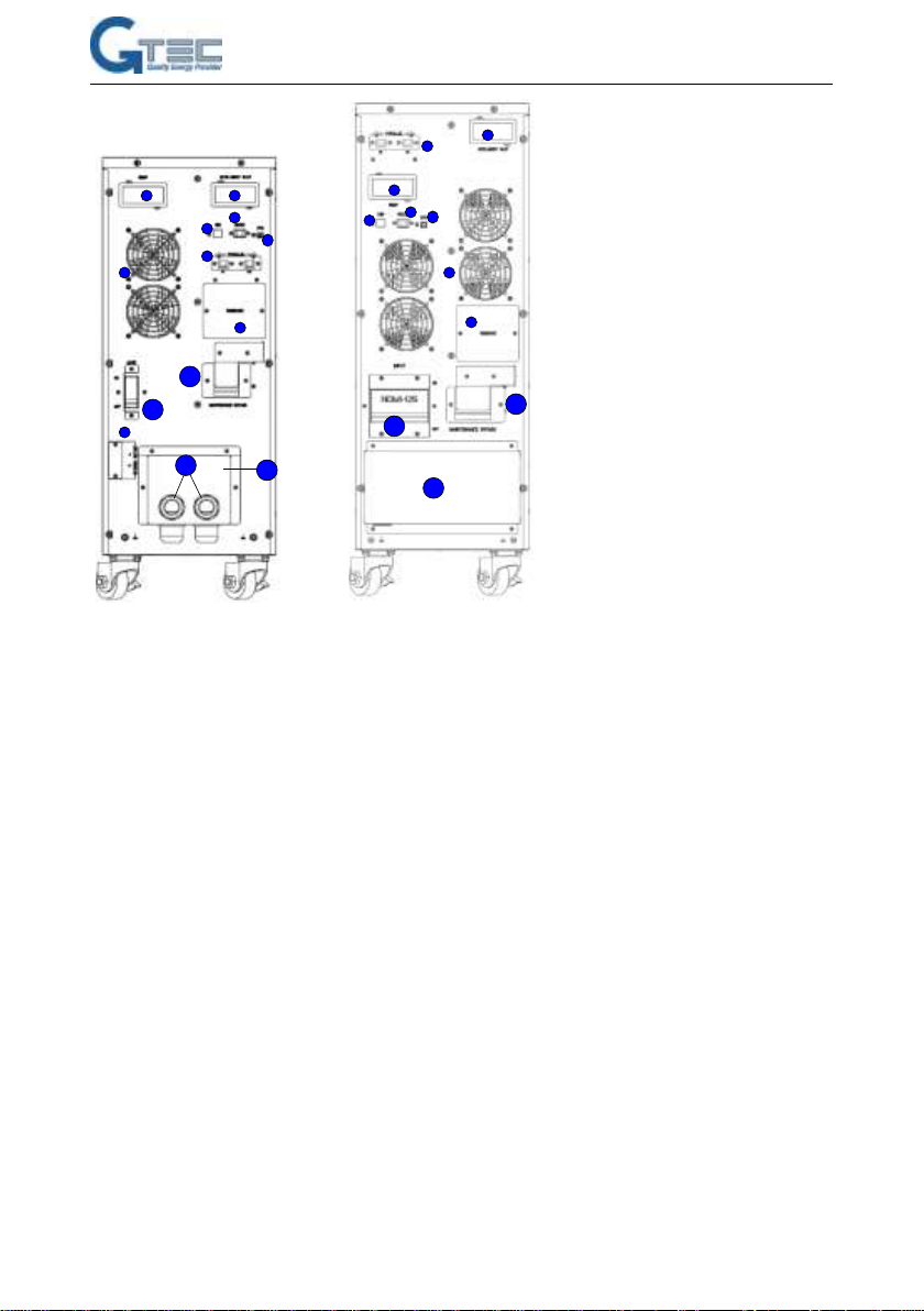
3. SYSTEM DESCRIPTION...........................................................................................................11
3.1TRANSIENT VOLTAGE SURGE SUPPRESSION (TVSS)AND EMI/FRI FILTERS................................ 11
3.2 RECTIFIER/POWER FACTOR CORRECTION (PFC)CIRCUIT......................................................... 11
3.3 INVERTER ............................................................................................................................11
3.4 BATTERY CHARGER...............................................................................................................12
3.5 DC-TO-DC CONVERTER........................................................................................................12
3.6 BATTERY..............................................................................................................................12
3.7 DYNAMIC BYPASS .................................................................................................................12
4. PRODUCT SPECIFICATION AND PERFORMANCES ..............................................................13
4.1 MODEL DESCRIPTION............................................................................................................13
4.2 PRODUCT SPECIFICATION AND PERFORMANCE.........................................................................13
5. INSTALLATION.........................................................................................................................15
5.1 UNPACKING AND INSPECTION .................................................................................................15
5.2 CONNECT INPUT/OUTPUT POWER...........................................................................................15
5.3 OPERATING PROCEDURE FOR CONNECTING THE LONG BACKUP TIME MODEL UPS WITH THE
EXTERNAL BATTERY ....................................................................................................................19
5.4 PARALLEL OPERATION............................................................................................................20

7
ZY120 6-20kVA (11) User Manual EN rev.04.doc
6. CONTROLS AND INDICATORS................................................................................................25
7. OPERATION..............................................................................................................................27
7.1 OPERATION MODE ................................................................................................................27
7.2 PARALLEL OPERATION...........................................................................................................28
7.3 MAINTENANCE BYPASS MODE................................................................................................29
8. BATTERY MAINTENANCE .......................................................................................................31
9. NOTES FOR BATTERY DISPASAL AND REPLACEMENT PROCEDURES .............................31
9.1 BATTERY DISPOSAL...............................................................................................................32
9.2 BATTERY REPLACEMENT PROCEDURES...................................................................................32
10. TROUBLE SHOOTING............................................................................................................33
10.1 CHECKING UPS STATUS ......................................................................................................33
10.2ADJUST THE FACTORS CAUSED THE PROBLEM.........................................................................33
ANNEX A. RATED PARAMETERS SET ON LCD..........................................................................38
ANNEX B. INTELLIGENT SLOT ...................................................................................................41
ANNEX C. EPO.............................................................................................................................42

8
ZY120 6-20kVA (11) User Manual EN rev.04.doc
1. ELECTROMAGNETIC COMPATIBILITY
* Safety
IEC/EN 62040-1
* EMI
Conducted Emission.........IEC/EN 62040-2
Category C3
Radiated Emission............IEC/EN 62040-2
Category C3
*EMS
ESD..................................IEC/EN 61000-4-2
Level 4
RS....................................IEC/EN 61000-4-3
Level 3
EFT..................................IEC/EN 61000-4-4
Level 4
SURGE............................IEC/EN 61000-4-5
Level 4
Low Frequency Signals..............:IEC/EN 61000-2-2
Warning: This is a product for commercial and industrial application in the second
environment-installation restrictions or additional measures may be needed to prevent
disturbances.
NOTICE:
This is a product for restricted sales distribution to informed partners. Installation restrictions
or additional measures may be needed to prevent radio interference.
Operated the UPS in an indoor enviroment only in an ambient temperature range of 0-40C
(32-104F). Install it in a clean environment, free from moisture, flammable liquids, gases and
corrosive substance.
This UPS contains no user-serviceable parts except the internal battery pack. The UPS on/off
push buttons do not electrically isolate internal parts. Under no circumstance attempt to gain
access internally, due to the risk of electric shock or burn.
Do not continue to use the UPS if the panel indications are not in accordance with these
operating instructions or the UPS performance alters in use. Refer all fault to your dealer.
Servicing of batteries should be performed or supervised by personnel knowledgeable of batteries
and the precautions. Keep unauthorized personnel away from the batteries. Proper disposal of
batteries is required. Refer to your local laws and regulations for disposal requirement.
DO NOT CONNECT equipment that could overload the UPS or demand DC current from the
UPS, for example: electric drills, vacuum cleaners, laser printers, hair dryer or any appliance using
half-wave rectification.
Storing magnetic media on top of the UPS may result in data loss or corruption.
Turn off and isolate the UPS before cleaning it. Use only a soft cloth, never liquid or aerosol
cleaners.

9
ZY120 6-20kVA (11) User Manual EN rev.04.doc
2. INTRODUCTION
Congratulations on your choice of the ZY120 uninterruptible power system (UPS), the UPS
comes in nominal power ratings of 6000VA,10000VA and 20000VA. It is designed to provide
conditioned power to microcomputers and other sensitive electronic equipment.
When it is generated, alternating current is clean and stable. However, during transmission
and distribution it may be subject to voltage sags, spikes and complete power failure that may
interrupt computer operations, cause data loss and even damage equipment. The UPS protects
equipment from these disturbances.
The UPS is a compact, on-line UPS.An on-line UPS continuously conditions and regulates its
output voltage, whether utility power is present or not. It supplies connected equipment with clean
sinewave power. Sensitive electronic equipment operates best from sinewave power.
For ease of use, the UPS features a LCD display to indicate all information for UPS, and
provide kinds of function buttons.
1 1
1
22
2
3
4
5
6
7
8
9
10
11
12
34
5
6
78
9
10
11
12
34
5
6
8
7
11
10
9
12
13 13
13
6K long backup model 10K long backup model 6K standard model

10
ZY120 6-20kVA (11) User Manual EN rev.04.doc
11
2
2
33
44
5
5
6
6
7 7
88
9
10
10
11 11
12 13
13
10K standard model 20K long backup model
Fig 2. Rear View
Function instructions:
1. SNMP card slot (option)
2. Dry contactor slot
3. USB port
4. RS232
5. EPO
6. Parallel ports (option)
7. Fans
8. Reserved customer function
9. External battery connector.
10. Internal manual bypass
11. Input breaker
12. Cable entry protector
13. Terminal cover

11
ZY120 6-20kVA (11) User Manual EN rev.04.doc
3. SYSTEM DESCRIPTION
3.1 Transient Voltage Surge Suppression (TVSS) and EMI/FRI Filters
These UPS components provide surge protection and filter both electromagnetic interference
(EMI) and radio frequency interference (RFI). They minimize any surge or interference present in
the utility line and keep the sensitive equipment protected.
3.2 Rectifier/Power Factor Correction (PFC) Circuit
In normal operation, the rectifier/power factor correction (PFC) circuit converts utility AC
power to regulated DC power for use by the inverter while ensuring that the waveform of the input
current used by the UPS is near ideal. Extracting this sinewave input current achieves two objects:
⚫The utility power is used as efficiency as possible by the UPS.
⚫The amount of distortion reflected on the utility is reduced.
This results in cleaner power being available to other devices in the building not being
protected by the UPS.
3.3 Inverter
In normal operation, the inverter utilize the DC output of the power factor correction circuit and
inverters it into precise, regulated sinewave AC power. Upon a utility power failure, the inverter
receives its required energy from the battery through the DC-to-DC converter. In both modes of
operation, the UPS inverter is on-line and continuously generating clean, precise, regulated AC

12
ZY120 6-20kVA (11) User Manual EN rev.04.doc
output power.
3.4 Battery Charger
The battery charger utilizes energy from the utility power and precisely regulates it to
continuously float charge the batteries. The batteries are being charged whenever the UPS is
connected to utility power.
3.5 DC-to-DC Converter
The DC-to-DC converter utilizes energy from the battery system and raises the DC voltage to
the optimum operating voltage for the inverter. The converter includes boost circuit which is also
used as PFC.
3.6 Battery
The 6K/10K Standard include value-regulated, non-spillable, lead acid batteries inside. To
maintain battery design life, operate the UPS in an ambient temperature of 15-25C.
3.7 Dynamic Bypass
The UPS provides an alternate path for utility power to the connected load in the unlikely
event of a UPS malfunction. Should the UPS have an overload, over temperature or any other
failure condition, the UPS automatically transfers the connected load to bypass. Bypass operation
is indicated by an audible alarm and illuminated amber Bypass LED. To manually transfer the
connected load from the inverter to bypass, press the ON/OFF button or Manual Bypass button
once.
NOTICE:The bypass power path does NOT protect the connected equipment from disturbances
in the utility supply.

13
ZY120 6-20kVA (11) User Manual EN rev.04.doc
4. PRODUCT SPECIFICATION and PERFORMANCES
4.1 Model Description
This manual is applicable to the following models:
“KS” Model: Long backup time
4.2 Product Specification and Performance
1. General Specification
Model
6kVA
6kVA-KS
10kVA
10kVA-KS
20kVA-KS
Power Rating
6KVA/5.4KW
10KVA/9KW
20KVA/18KW
Frequency (Hz)
50/60
50/60
50/60
Input
Voltage
(176-275)VAC
(176-275)VAC
(176-275)VAC
Current
34Amax.
57Amax
115A max
Battery
Voltage
192VDC
192VDC
192VDC
Current
37Amax
60Amax
120Amax
I recharge
1A
5A
1A
5A
5A
Output
Voltage
220V/230V/240V
Current
27/26/25A
45/43/42A
91/87/83A
Dimension
(WxDxH) mm
250*526*640
250*526*480
250*526*640
250*526*480
250*544*750
Weight (kg)
57
18
65
20
33
Factory setting 230Vac-50Hz
Model No.
Type
6kVA
Standard
10kVA
6kVA-KS
Long backup time
10kVA-KS
20kVA-KS

14
ZY120 6-20kVA (11) User Manual EN rev.04.doc
2. Electrical Performance
Input
Model
Voltage
Frequency
Power Factor
UPS
Single-phase
40-70Hz
>0.99(Full load)
3. Operating Environment
Temperature
Humidity
Altitude
Storage temperature
0C-40C
<95%
<1000m
0C-70C
NOTICE:If the UPS is installed or used in a place where the altitude is above than 1000m, the
output power must be derated in use, please refer to the following:
Altitude (M)
1000
1500
2000
2500
3000
3500
4000
4500
5000
Derating Power
100%
95%
91%
86%
82%
78%
74%
70%
67%
Output
Voltage
Regulation
Power
Factor
Frequency
tolerance.
Distortion
Overload capacity
Crest ratio
1%
0.9 lag
0.1% of
normal
THD<1%
Full load
(Linear
Load)
110% load: transfers to
Bypass mode after 1 hour
130% load: transfers to
Bypass mode after 1 minute
150% load :transfers to
Bypass mode after 0.5
minute and shutdown the
output after 1 minute
3:1
maximum

15
ZY120 6-20kVA (11) User Manual EN rev.04.doc
5. INSTALLATION
The system should be installed and wired only by qualified electricians in accordance with
applicable safety regulations.
NOTICE:UPS operation in sustained temperature outside the range of 15-25
C (59
-77
F)
reduces battery life.
5.1 Unpacking and Inspection
1) Unpack the packaging and check the package contents. The shipping package contains:
●1 UPS
●1 user manual
●1 redAnderson connector and 1 black Anderson connector (6K and 10K)
●2 output cables
●2 cable entry protector (6K and 10K)
● 1 CD with monitoring software UPSilon , setting software MTR e driver.
2) Inspect the appearance of the UPS to see if there is any damage during transportation. Do not
turn on the unit and notify the carrier and dealer immediately if there is any damage or lacking
of some parts.
5.2 Connect Input/Output Power
1. Notes for installation
1) The UPS must be installed in a location with good ventilation, far away from water,
inflammable gas and corrosive agents.
2) Ensure the air vents on the front and rear of the UPS are not blocked. Allow at least 0.5m
of space on each side.
3) Condensation to water drops may occur if the UPS is unpacked in a very low temperature
environment. In this case it is necessary to wait until the UPS is fully dried inside out
before proceeding installation and use. Otherwise there are hazards of electric shock.
2. Installation
Installation and wiring must be performed in accordance with the local electric code and the
following instructions by professional personnel.
It’s suggested to install input protection breaker upstream the UPS. Here below the references:
ZY120-6K / KS: 32A curve C 250Vac , 40A-2P curve C 250Vac (Ks)
ZY120-10K / KS: 63A-2P curve C 250Vac,

16
ZY120 6-20kVA (11) User Manual EN rev.04.doc
ZY120-20K-KS: 125A-2P curve C
For safety, please cut off the mains power switch before installation. Open the battery breaker for
long backup time model (“KS” model).
1) Open the terminal block cover located on the rear panel of the UPS, please refer to the
appearance diagram.
2) For 6k(KS) UPS, it is recommended to select the UL1015 10AWG(6mm2) wire or other
insulated wire which complies with AWG Standard for the UPS input and output wirings.
3) For 10k(KS) UPS, it is recommended to select the UL1015 8AWG(10mm2) wire or other
insulated wire which complies withAWG Standard for the UPS input and output wirings.
4) For 20k(KS) UPS, it is recommended to select the UL1015 6AWG(25mm2) wire or other
insulated wire which complies with AWG Standard for the UPS input wires and output
wirings. It is better to use 3 wires (UL1015 10AWG) connecting inputA/B/C separately from
same source as fig.4.
NOTICE:Do not use the wall receptacle as the input power source for the UPS, as its rated current is
less than the UPS’s maximum input current. Otherwise the receptacle may be burned and destroyed.
For the long backup time modes, make sure that the capacity of batteries is larger than 24AH to avoid
over charging.
5) For 6-10K, connect the input and output wires to the corresponding input and output
terminals according to the fig.3. Make sure that wires be connected to terminals through
cable entry protector shown as fig.3:

17
ZY120 6-20kVA (11) User Manual EN rev.04.doc
(a) Cables entry
(b) Wiring connection
Fig 3. Input and Output Terminal Block Wiring Diagram of 6K(KS)/10K(KS)
Take out Anderson connector and make battery cables according to site’s application shown as
below:
NOTICE: make sure that the red Anderson connector be connected to battery +and the black
Anderson connector be connected to battery -, or else it may destroy UPS.
6) For 20K(KS),connect the input 3 line wires to input A/B/C separately as fig.4. Or connect
1 input wire to input C.

18
ZY120 6-20kVA (11) User Manual EN rev.04.doc
(a)Cables entry
(b) Wiring connection
Fig 4. Input and Output Terminal Block Wiring Diagram of 20K(KS)
NOTICE:You must make sure that the input and output wires and the input and output terminals are
connected tightly.
NOTICE: Please make sure that if there is a copper bar shorting input A/B/C terminal for UPS 20K-KS,
or else you must contact with supplier.
7)The protective earth ground wire refers to the wire connection between the equipment
which consumes electric equipment and the ground wire. The wire diameter of protective
earth ground wire should be at least as above mentioned for each model and green wire
or green wire with yellow ribbon wire is used.
8)For 6K and 10K UPS,
9)After having completed the installation, make sure the wiring connection is correct.
10)Please install the output breaker between the output terminal and the load, and the
breaker should with leakage current protective function if necessary.
11) To connect the load with the UPS, please turn off all the loads first, then perform the
connection and finally turn on the loads one by one.

19
ZY120 6-20kVA (11) User Manual EN rev.04.doc
12) No matter the UPS is connected to the utility power or not, the output of the UPS may have
electricity. The parts inside the unit may still have hazardous voltage after turning off the
UPS. To make the UPS have no output, power off the UPS, and then disconnect the utility
power supply.
13) Suggest charging the batteries for 8 hours before use. After connection, turn the input
breaker in the “ON” position, the UPS will charge the batteries automatically. You can also
use the UPS immediately without charging the batteries first, but the backup time may be
less than the standard value.
14) If it is necessary to connect the inductive load such as a monitor or a laser printer to the
UPS, the start-up power should be used for calculating the capacity of the UPS, as its
start-up power consumption is too big when it is started.
5.3 Operating procedure for connecting the long backup time model
UPS with the external battery
Take out Anderson connector and make battery cables according to site’s application
shown as below:
NOTICE: make sure that the red Anderson connector be connected to battery +and the
black Anderson connector be connected to battery -, or else it may destroy UPS. For the
long backup time modes, make sure that the capacity of batteries is larger than 24AH to
avoid over

20
ZY120 6-20kVA (11) User Manual EN rev.04.doc
1. The nominal DC voltage of external battery pack is 192VDC. Each battery pack consists of
16 pieces of 12V maintenance free batteries in series. To achieve longer backup time, it is
possible to connect multi-battery packs, but the principle of “same voltage, same type”
should be strictly followed.
2. For UPS 20K-KS, select the UL1015 6AWG(25mm2) wire or other insulated wire which
complies with UL Standard for the UPS battery wirings. The procedure of installing battery
bank should be complied with strictly. Otherwise you may encounter the hazardous of
electric shock.
1) A DC breaker must be connected between the battery pack and the UPS. The
capacity of breaker must be not less than the data specified in the general
specification.
2) Set the battery pack breaker in “OFF” position and connect the 16 pieces of batteries
in series.
3) You must connect the external battery cable to the battery first, if you connect the
cable to the UPS first, you may encounter the hazardous of electric shock. The
positive pole of the battery is connected to the UPS with red wire; the negative pole
of the battery is connected to the UPS with black wire; the green and yellow ribbon
wire is connected to the ground of the battery cabinet.
3. To complete the connection of the external battery cable into the UPS. Do not attempt to
connect any loads to the UPS now. You should connect the input power wire to the right
position first. And then set the breaker of the battery pack in the “ON”position. After that
set the input breaker in the “ON”position. The UPS begins to charge the battery packs at
the time.
5.4 Parallel operation
1. Brief introduction
As long as the UPS is equipped with parallel cables, up to 3 UPSs can be connected in
parallel to realize output power sharing and power redundancy.
2. Parallel installation
1) Users need to opt two standard 15-pin communication cables which length is
appropriate to be less than 3m. shown as fig.5:
Other manuals for ZY120
1
This manual suits for next models
5
Table of contents
Other Gtec UPS manuals
Popular UPS manuals by other brands

Maco
Maco 480987 Installation and operating instructions

Lowell
Lowell UPS8-2000 User & installation manual

Keatec Energy
Keatec Energy T SERIES user guide

CyberPower
CyberPower Value1200ELCD quick start guide

Powerware
Powerware 9330 Installation & operation manual

Ametek
Ametek Powervar Security II Series manual