gtm KTN-ZD Series User manual

Operating manual
Nominal Force
5 N - 1000 kN
Force Transfer Standard
Series KTN-ZD

© GTM Testing and Metrology GmbH
All rights reserved. This document may not be photocopied, duplicated in any other
form or translated into another language either in whole or in part without the prior
written consent of GTM.
The content of these manual is intended solely for information purposes and can be
changed at any time without prior notification.
With regard to the warranty and liability, we refer expressly to our 'General commercial
terms and conditions' (www.gtm-gmbh.com) and the instructions and regulations con-
tained in these installation and operating instructions.
GTM Testing and Metrology GmbH
Philipp-Reis-Straße 4-6
64404 Bickenbach
Deutschland
Tel: +49 6257 9720-0
Fax: +49 6257 9720-77
contact@gtm-gmbh.com
www.gtm-gmbh.com

www.gtm-gmbh.com
Series KTN-ZD (eng.) 16/09/2022 Page 3
#PrecisionWins
Table of contents
1. Product description.............................................................................. 4
1.1 Designated use........................................................................... 4
1.2 Exempted use............................................................................. 4
2. Safety instructions................................................................................ 5
3. Storage and transport instructions ..................................................... 9
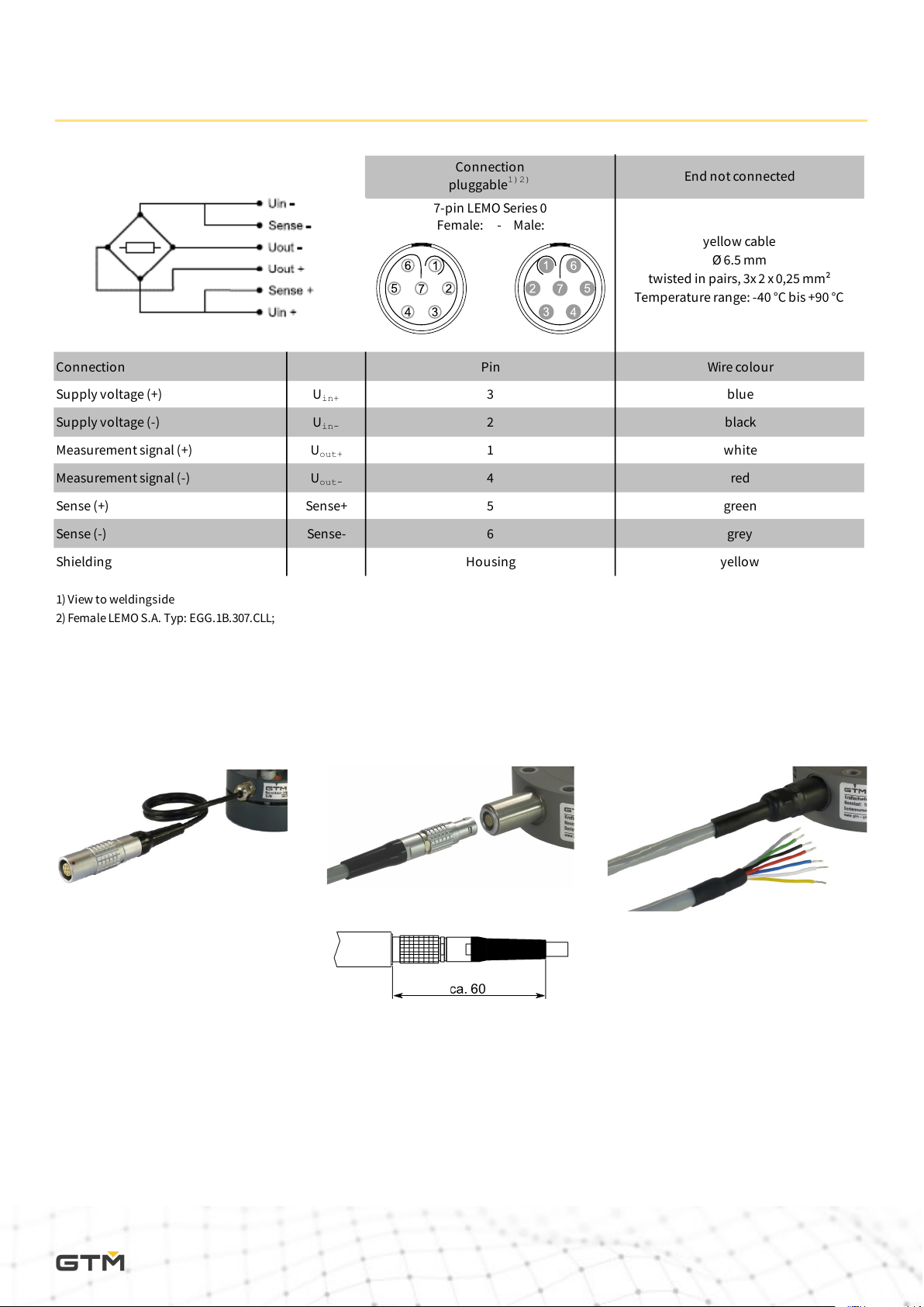
4. Cable connection ............................................................................... 10
5. Double Bridge ..................................................................................... 11
6. Bending Moment Measuring Circuits ................................................ 12
7. Temperature Measurement ............................................................... 13
8. Application instructions .................................................................... 14
8.1 Assembly instruction............................................................... 14
9. Mating dimensions ............................................................................. 15
9.1 Construction size 5 N - 100 N................................................... 15
9.2 Construction size 200 N - 2500 N............................................. 16
9.3 Dimensions of construction size 5 N - 2500 N ........................ 17
9.4 Construction size 5 kN - 100 kN............................................... 18
9.5 Construction size 200 kN - 500 kN.......................................... 19
9.6 Construction size 1000 kN ...................................................... 20
9.7 Dimensions of construction size 5 kN - 1000 kN .................... 21
10. Technical Data..................................................................................... 22
10.1 Class 00 | Construction size 5 N - 500 N................................... 22
10.2 Class 00 | Construction size 1 kN - 1000 kN............................. 23
10.3 Class 0,5 | Construction size 5 N - 500 N.................................. 24
10.4 Class 0,5 | Construction size 1 kN - 1000 kN............................ 25
11. Technical support ............................................................................... 26
12. Declaration of incorporation.............................................................. 27

www.gtm-gmbh.com
Series KTN-ZD (eng.) 16/09/2022 Page 4
#PrecisionWins
1. Product description
1.1 Designated use
The force transducer of the KTN-ZD series is is suitable for measuring uniaxial
tensile and compressive forces and is used for calibration of static measuring
machines, for example in accordance with ISO 376. For safe operation, original
force introducing components must be used.
Any other use is not intended and is therefore prohibited. No claims may be
made for damage resulting from inappropriate use.
The limit values for the total load and all other limits must be complied with.
1.2 Exempted use
The force transducer is not suitable for dynamic applications. The force trans-
ducer is not a safety component. You must not use it in a complete system in
which its failure may lead to the life and well being of people being endange-
red.
The transducer is not suitable or approved for use in potentially explosive
areas.
Force Transducer Standard Series KTN-ZD

www.gtm-gmbh.com
Series KTN-ZD (eng.) 16/09/2022 Page 5
#PrecisionWins
2. Safety instructions
Markings used
The following designations and symbols are used in the operating manual
to identify hazards:
▶ Denotes handling instructions
Denotes lists
DANGER!
Denotes a possibly hazardous situation that can lead to physical
injuries or death.
DANGER!
Denotes a hazardous situation due to electrical voltage that can
lead to physical injuries or death.
NOTE!
Denotes usage tips, general information and other useful notes.
DANGER OF BURSTING!
Denotes a potentially hazardous situation that can cause physical
injuries or death if ignored.
Safety instructions

www.gtm-gmbh.com
Series KTN-ZD (eng.) 16/09/2022 Page 6
#PrecisionWins
Additional regulations
This operating manual contains the most important notes for safe operation
of the transducer. Consideration must also be given to the legal and safety re-
gulations applicable at the operating location, the accident prevention regula-
tions applicable at the operating location and the technical data in connection
with the safety regulations listed here.
Residual hazards
The transducer of series KTN-ZD is state-of-the-art technology and safe to
operate.
Residual hazards can arise during operation if the devices are used and opera-
ted improperly by unqualified personnel.
The scope of delivery for the transducer only covers a partial area of mechat-
ronic metrology. The safety-related criteria for using the transducer within a
complete system must be taken into account by the system design engineer,
the equipment manufacturer and/or the operator so that residual hazards are
minimised. Reference must be made to the remaining residual hazards in the
DANGER!
In the case of a complete system, the safety-related criteria must
be taken into account so that any failure of the transducer does not
present a hazard to anyone.
Safety instructions

www.gtm-gmbh.com
Series KTN-ZD (eng.) 16/09/2022 Page 7
#PrecisionWins
Transducer condition and modifications
You may only operate the transducer in a perfect condition while complying
with the instructions given in the operating manual.
The transducer must not be modified either in its design or safety-related fea-
tures, without our express, written permission.
Personnel qualifications
The transducer and additional components must only be operated and as-
sembled by qualified personnel. Qualified personnel are those persons who
are acquainted with the assembly, commissioning and operation of the trans-
ducer and who have the appropriate qualifications for their job.
Safety instructions
DANGER OF BURSTING!
Do not overload the transducer!
The attached parts must also be designed to bear the maximum load.
Only use attached parts in an appropriate condition.
In case of new, untested designs, you must provide additional protec-
tive measures against bursting parts.
Overloading
All transducers of this series have already been subjected to an overload test
at the manufacturer's. No additional overloads are permissible; always com-
ply with the nominal loads of the transducer.
NOTE
GTM oers training courses to qualify personnel.

www.gtm-gmbh.com
Series KTN-ZD (eng.) 16/09/2022 Page 8
#PrecisionWins
Ambient conditions
The transducer is intended for use in enclosed rooms while complying with
the ambient conditions detailed in the technical specifications.
Safety instructions
The tranducer is not permitted for use in potentially explo-
sive areas.
Protect the transducer against the influences of weather,
such as rain and snow. Take appropriate measures on-site
against power surges, e.g. from lightning strike.
No welding circuits may be introduced through the body of
the transducer. If in doubt, you must dismantle the trans-
ducer.
DANGER!
The transducer is not suitable for:
- Potentially explosive areas
- Power surges
- Welding circuits

www.gtm-gmbh.com
Series KTN-ZD (eng.) 16/09/2022 Page 9
#PrecisionWins
3. Storage and transport instructions
Storage and transport instructions
The transducer series KTN-ZD is a precision measuring device and must be
handled with appropriate caution.
▶ If the transducer is dropped or jolted it can become damaged prohibiting
any further use.
▶ During storage, secure rotationally symmetrical transducers and attach-
ment parts from rolling away.
▶ Only use the original transport packaging and other appropriate cut-to-size
packaging for storage and transport.

www.gtm-gmbh.com
Series KTN-ZD (eng.) 16/09/2022 Page 10
#PrecisionWins
4. Cable connection
Cable connection
▶ pluggable cable connection from 200 N ▶ permanent cable connection,
end not connected
x x
Connection
pluggable1)2) End not connected
7-pin LEMO Series 0
Female: - Male:
yellow cable
Ø 6.5 mm
twisted in pairs, 3x2 x0,25 mm²
Temperature range: -40 °C bis +90 °C
Connection Pin Wire colour
Supply voltage (+)
Uin+ 3 blue
Supply voltage (-)
Uin- 2 black
Measurement signal (+)
Uout+ 1 white
Measurement signal (-)
Uout- 4 red
Sense (+) Sense+ 5 green
Sense (-) Sense- 6 grey
Shielding Housing yellow
1) View to weldingside
2) Female LEMO S.A. Typ: EGG.1B.307.CLL;
Male: FGG.1B.307.CLA.D72
▶ pluggable cable connection ; 5 N to 100 N

www.gtm-gmbh.com
Series KTN-ZD (eng.) 16/09/2022 Page 11
#PrecisionWins
5. Double Bridge
Option: Double Bridge
▶ For transducers with a double measuring bridge the second signal is mea-
sured by means of an additional plug. The respective electrical connec-
tions can be found in the chapter Technical Data.

www.gtm-gmbh.com
Series KTN-ZD (eng.) 16/09/2022 Page 12
#PrecisionWins
6. Bending Moment Measuring Circuits
Option: Bending Moment Measuring Circuits
▶ During the test of force and torque introduction the bending moments Mx
and My are measured and output as separate channels.
▶ Position of the coordinate cross
Nominal force
Fnom kN 0.2 - 200
(2mV/V)
Temperature effect on
characteristicvalue per 10 K
TK C%/10 K 0.2
Temperature effect on
zero signal per 10 K
TK 0%/10 K 0.2
Rated characteristicvalue C nom mV/V 1)
Input resistance
ReΩ400
Operating range of
excitation voltage BU, G V 5 - 12
1) Specification shown on thelabel

www.gtm-gmbh.com
Series KTN-ZD (eng.) 16/09/2022 Page 13
#PrecisionWins
7. Temperature measurement
Option: Temperature measurement
▶ For Type PT100 transducers with an integrated temperature sensor, obser-
ve the basic values of the resistors of the platinum measuring coils with a
nominal resistance of 100 Ohms at 0°C.
These values and the permissible deviations correspond to DIN EN 60751.
Temperature range: see nominal temperature range in Technical Data
Connection type: 4 Conductor technology
Permanent connection
end not connected
Black cable 4-wire
Ø 2,2 mm
4 x0,04 mm²
Temperature range:
-50 °C bis +105 °C
6-pin LEMO Series 0
Female: - Male:
15-pin Sub-D
male
Connection Color Pin Pin
U (+) A White 1 5
Sense (+) B Red 3 12
U (-) C Black 4 6
Sense (–) D Green 6 13
Shielding E Housing Housing Housing
1) View to weldingside
Permanent connection 1)

www.gtm-gmbh.com
Series KTN-ZD (eng.) 16/09/2022 Page 14
#PrecisionWins
8. Application instructions
Application instructions
✓XX
8.1 Assembly instruction
▶ Avoid mechanical strain on the cable and the connector.
▶ Wear gloves if you wish to touch the transducer during a series of measurements.
▶ Avoid a deformation of the assembly surfaces. This could aect the measurement.
▶ Screw the attaching parts with the total usable thread depth of the threaded adap-
ter. The attachment must not rest on the measuring body.
▶ Pay attention to the cleanliness of the mounting surfaces and connections. They
should be cleaned from dust and dirt before mounting and measuring, otherwise the
measuring would be influenced.

www.gtm-gmbh.com
Series KTN-ZD (eng.) 16/09/2022 Page 15
#PrecisionWins
9. Mating dimensions
Mating dimensions
9.1 Construction size 5 N – 100 N
▶ Standard equipment ▶ Accessories: thrust piece ▶ Accessories: tension adaption

www.gtm-gmbh.com
Series KTN-ZD (eng.) 16/09/2022 Page 16
#PrecisionWins
Mating dimensions
9.2 Construction size 200 N – 2500 N
▶ Standard equipment ▶ Accessories: thrust piece ▶ Accessories: tension adaption

www.gtm-gmbh.com
Series KTN-ZD (eng.) 16/09/2022 Page 17
#PrecisionWins
Mating dimensions
9.3 Dimensions of construction size 5 N – 2500 N
Nominal force
compression/tension
± F nom N 5 10 20 50 100 200 500 1000 2500
Diameter
ØD 1mm
Diameter
ØD 2mm
Diameter
ØD 3mm
Diameter
ØD 4mm
Diameter
ØD 5mm
Diameter
ØD 6mm
Thread
T1
Thread
T2
Thread
T3
Thread
T4
Height
H1mm
Height
H2mm
Height
H3mm
Height
H4mm
Height
H5mm
Height
H6mm
Height
H7mm
Height
H8mm
Height
H9mm
Height
H10 mm
Height
H11 mm
Height
H12 mm
Height
H13 mm
Height
H14 mm
100
20
1
M5
M8
---
10
35
32
11.95-0.05
25
77
30
72
14
M5
M5
14
M5
M8
M20x1.5
45.7
52.7
10
45
104
10
253.7
16.4
61.4
---
---
44
74.5
32.5
43
27.5
22
245.5
94.5
100
104
24.8
---
---
20
---
20

www.gtm-gmbh.com
Series KTN-ZD (eng.) 16/09/2022 Page 18
#PrecisionWins
Mating dimensions
9.4 Construction size 5 kN – 100 kN
▶ Standard equipment ▶ Accessories: thrust piece ▶ Accessories: tension adaption

www.gtm-gmbh.com
Series KTN-ZD (eng.) 16/09/2022 Page 19
#PrecisionWins
Mating dimensions
9.5 Construction size 200 kN – 500 kN
▶ Standard equipment ▶ Accessories: thrust piece ▶ Accessories: tension adaption

www.gtm-gmbh.com
Series KTN-ZD (eng.) 16/09/2022 Page 20
#PrecisionWins
Mating dimensions
9.6 Construction size 1000 kN
▶ Standard equipment ▶ Accessories: thrust piece ▶ Accessories: tension adaption
Table of contents
Popular Accessories manuals by other brands

MESTIC
MESTIC MAC-40 Instructions for use

BeeWi
BeeWi BP1WC quick start guide

SUNPRO
SUNPRO Retractable Awning installation manual

BEMKO
BEMKO TOKAR PLD-260-120 installation instructions

Heatcraft
Heatcraft Bohn PRO3 Installation and operation manual

Hytronik
Hytronik HMW39/RF Installation and instruction manual