Einbauanleitung(c) Installation Instructions Notice d'installation
Deutsch /
Français
(b) Description
THE SIPHA SENSOR AND ACTUATOR HEAD MUST ONLY BE USED
WITH A GUARDMASTER SIPHA CONTROL UNIT.
The Guardmaster Sipha guard interlock switch system is self
monitoring and comprises a coded magnetic actuator and sensor
connected via two wiring channels to a control unit.
Beschreibung
Die SIPHA SENSOR- UND BETÄTIGERELEMENTE DÜRFEN NUR IN
VERBINDUNG MIT EINEM GUARDMASTER-STEUERGERÄT SIPHA
VERWENDET WERDEN.
Das Schutztür-Verriegelungsschaltersystem ist selbstüberwachend und
besteht aus je einem codierten Magnetsensor und Betätiger, die über
zwei Leiterkanäle an ein SIPHA Steuergerät angeschlossen sind.
Description
LE BLOC CONTACT ET EMETTEUR SIPHA DOIT ETRE UTILISÉ
EXCLUSIVEMENT AVEC UN BLOC LOGIQUE DE CONTROLE GUARDMASTER
SIPHA.
Le système d’interverrouillage Guardmaster Sipha est un dispositif à auto-
surveillance, doté d’un bloc contact et émetteur magnétique codé relié à
un bloc logique de contrôle à travers deux conduits de câblage.
SIPHA
SENSORS & ACTUATORS
1
2
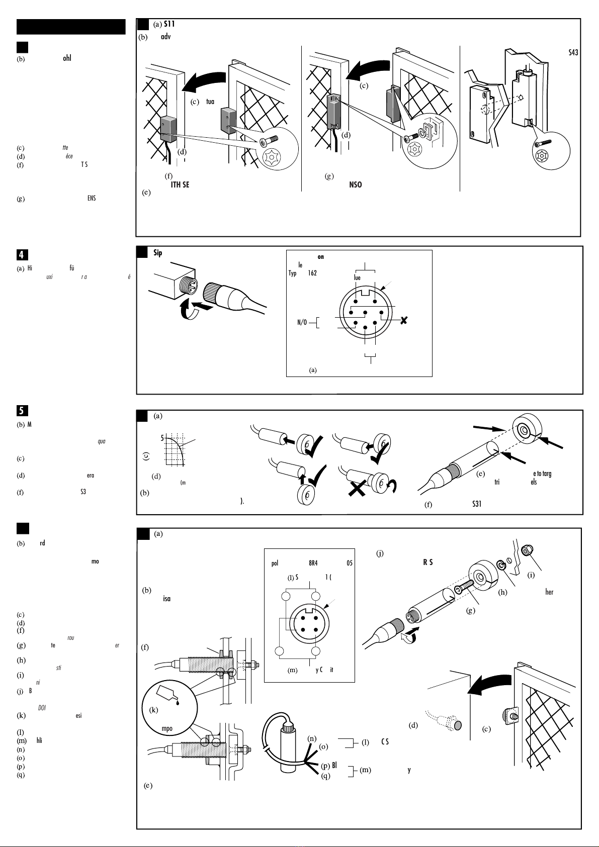
(b) Max. Versatz (bei Montage auf nicht-
ferromagnetischem Material) /
Tolérance au mauvais alignement (quand
il est monté sur un support non ferreux)
(c) Abstand (mm) Magnetfläche zu
Magnetfläche /
Distance face à face (mm).
(d) Seitliche Fluchtungsfehlertoleranz (mm) /
Tolérance d’erreur d’alignement (mm).
(e) Betriebsposition: Zielscheiben gegenüber /
Mise en œuvre : cibles face à face
.
(b)
ANMERKUNG: DER BETÄTIGER DARF
DEN SENSOR NICHT BERÜHREN
/
REMARQUE : L'EMETTEUR NE DOIT
PAS HEURTER LE CONTACT
.
(c) Schutztür-Arretierungen /
Butées de porte.
(d) Empfohlener Abstand zwischen Sensor und
Betätiger. /
Espace recommandé
entre l'émetteur et le récepteur.
(e) Sensor /
Contact.
(f) Betätiger /
Emetteur.
(g)
Bei Schwenktüren ist der Schalter an der
Schließkante anzubringen. Wenn zwei Schalter
benachbart montiert werden, sollten sie nicht
näher als 25 mm zueinander angebracht werden.
Pour les portes à charnières installer le contact
à l'intérieur de l'enceinte. Quand 2 contacts
sont côte à côte, les séparer d'une distance
de 25 mm au moins.
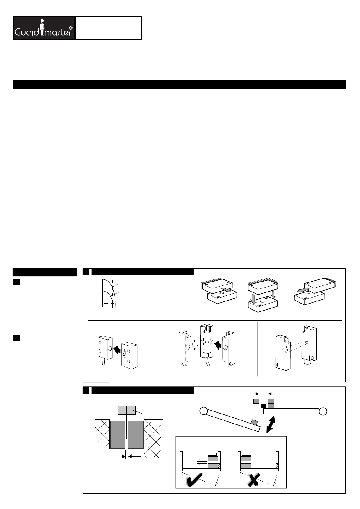
(h) SCHWENKBARE SCHUTZTÜREN
Schaltermontage an der Öffnungsseite
der Schutztür /
PORTES OU PROTECTEURS À CHARNIÈRES
Monter l’interrupteur sur le bord ouvrant
de la porte de protection
INTERVERROUILLAGE A CODAGE MAGNÉTIQUE BLOC CONTACT ET EMETTEUR
(a) CODED MAGNETIC INTERLOCK SENSOR AND ACTUATOR
CODIERTER MAGNETVERRIEGELUNGSSENSOR UND BETÄTIGER
(e) Sensor (f) Actuator
≥25mm
(g)
On hinged doors, install sensor at opening
edge. Where 2 sensors are mounted adjacent,
they should be no closer than 25mm.
(e)
Operation: target face to target face
(b) Misalignment Tolerance
(when mounted on non-ferrous materials).
5
0mm
(c) Face to face
distance (mm)
(d) Lateral misalignment
tolerance (mm)
(c)
Guard Stops
(d)
Recommended gap between sensor and actuator.
(a) S11, S12, S13, S21, S22, S23, S42, S43 Sensor
(a) S11, S12, S13, S21, S22, S23, S31, S42, S43 Sensor
(b)
NOTE: ACTUATOR MUST NOT STRIKE SENSOR
RETAIN THESE INSTRUCTIONS
THE SIPHA SENSOR AND ACTUATOR HEAD MUST NOT BE USED WITHOUT A
GUARDMASTER SIPHA 1 OR SIPHA 2 CONTROL UNIT.
Installation must be in accordance with the following steps and must be carried
out by suitably competent personnel.
This device is intended to be part of the safety related control system of a
machine. Before installation, a risk assessment should be performed to determine
whether the specifications of this device are suitable for all foreseeable
operational and environmental characteristics of the machine to which it is to be
fitted.
At regular intervals during the life of the machine check whether the
characteristics foreseen remain valid and inspect this device for evidence of
accelerated wear, material degradation or tampering. If necessary the device
should be replaced . Guardmaster cannot accept responsibility for a failure of this
device if the procedures given in this sheet are not implemented or if it is used
outside the recommended specifications in this sheet.
The interlock is not to be used as a mechanical stop.
Guard stops and guides must be fitted.
Exposure to shock and/or vibration in excess of those stated in
IEC 68 part: 2-6/7 should be prevented.
Adherence to the recommended inspection and maintenance instructions forms
part of the warranty.
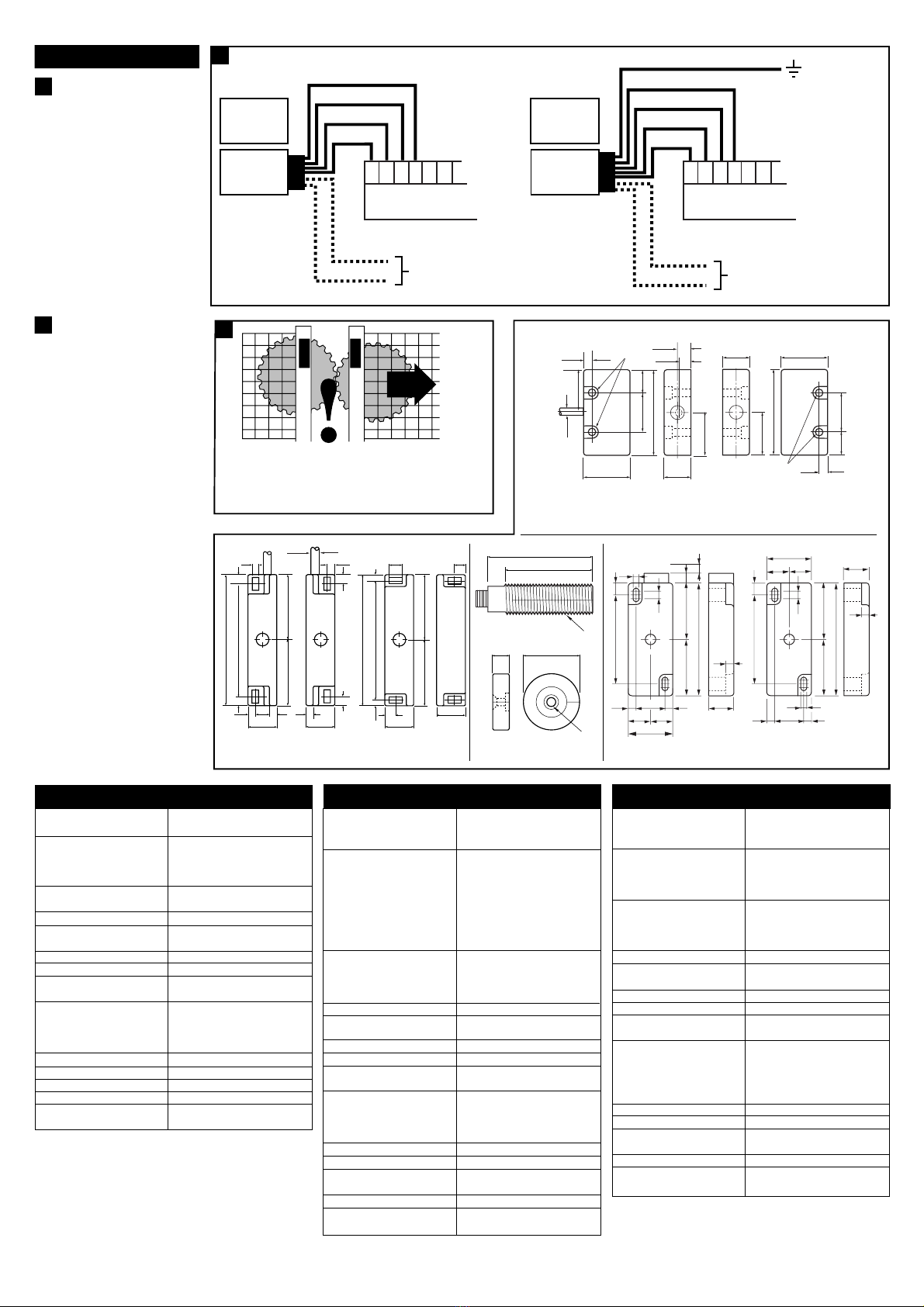
When a single sensor is connected to the control unit a single safety related fault
at the sensor, connecting wiring or inside the control unit will be detected either
immediately or at the next opening of the guard (depending on the type of
fault). When the fault is detected the control unit goes to a lock out condition. The
output contacts will not close until the fault has been rectified.
If multiple sensors are connected to the control unit each guard door should be
opened and then shut individually.
Otherwise some single faults may not be detected and unintentional lockout reset
may occur if two or more guard doors are open at the same time.
min 1mm
max 3mm
3
S11, S12, S13, S42, S43
S21, S22, S23
4
9
1
2
(e) Sensor
(f) Actuator
DIESE ANLEITUNG AUFBEWAHREN
Die SIPHA SENSOR- UND BETÄTIGERELEMENTE DÜRFEN NICHT OHNE EIN
GUARDMASTER-STEUERGERÄT SIPHA 1 ODER SIPHA 2 VERWENDET WERDEN.
Die Montage ist entsprechend den folgenden Schritten durch geeignet
qualifiziertes Fachpersonal durchzuführen.
Die Vorrichtung ist als Teil eines sicherheitsrelevanten Kontrollsystems einer
Maschine beabsichtigt. Vor der Installation sollte eine Risikobewertung zur
Festlegung dessen erfolgen, ob die Spezifikationen dieser Vorrichtung für alle
vorhersehbaren betrieblichen und umweltbezogenen Eigenschaften der
jeweiligen Maschine geeignet sind, an der sie installiert werden soll.
Zu regelmäßigen Abständen während der Lebensdauer der Maschine
überprüfen, ob die vorgesehenen Eigenschaften weiterhin zutreffen, und die
Vorrichtung auf Anzeichen von fortgeschrittenem Verschleiß,
Materialermüdung und unbefugte Eingriffe untersuchen. Falls erforderlich,
sollte die Vorrichtung ausgetauscht werden.
Guardmaster kann keinerlei Verantwortung für ein Versagen dieser Vorrichtung
übernehmen, wenn die in diesem Datenblatt gegebenen Verfahrensweisen nicht
implementiertt werden, oder wenn sie außerhalb der auf diesem Blatt
empfohlenen Spezifikationen verwendet wird.
Der Sicherheitsschalter darf nicht als ein Anschlag verwendet werden.
Schutztürarretierungen und Führungen sind vorzusehen.
Eine Aussetzung an Stoßbelastungen und/oder Vibrationen, die oberhalb den in
IEC 68, Teil 2-6/7 angegebenen Werten liegen, sollte verhindert werden.
Die Einhaltung der empfohlenen Inspektions- und Wartungsvorschriften ist Teil
der Garantie.
Bei Anschluß eines einzelnen Sensoren an das Steuergerät wird ein
sicherheitsrelevanter einzelner Fehler des Sensoren, in der Anschlußverkabelung
oder im Steuergerät selbst entweder sofort, oder beim nächsten Öffnen der
Schutztür (abhängig von der Art des Fehlers) erfaßt. Bei Erfassung eines Fehlers
wird das Steuergerät in einen Sperrzustand versetzt, d.h. die Ausgangskontakte
können erst nach Beseitungung des Fehlers erneut schließen.
Bei Anschluß von mehreren Sensoren am Steuergerät sollte jede Schutztür
einzeln geöffnet und geschlossen werden, weil sonst einige einzelne Fehler
möglicherweise nicht erfaßt werden, und eine unbeabsichtigte Rückstellung
des Sperrzustandes aufgrund von zwei oder mehreren, zur gleichen Zeit
geöffneten Schutztüren erfolgen könnte.
INSTRUCTIONS A RETENIR
LE BLOC CONTACT ET EMETTEUR SIPHA NE DOIT PAS ETRE UTILISÉ SANS UN
BLOC LOGIQUE DE CONTROLE GUARDMASTER SIPHA 1 OU SIPHA 2.
L’installation doit être réalisée par du personnel qualifié qui respectera les étapes
suivantes.
Ce système est conçu pour être implanté dans la partie sécurité du système de
commande d’une machine. Avant l’installation, il faut effectuer une appréciation
des risques pour vérifier que les caractéristiques de cet appareil sont appropriées
aux critères d’utilisation et d’environnement de la machine.
Pendant toute la vie de la machine, en respectant des périodes de vérifications
régulières, Assurez-vous que l’appareil conserve ses performances, inspectez le
montage du dispositif pour déceler les traces éventuelles d’usure, de dégradation
ou de fraudes. Si nécessaire, remplacez l’appareil. Guardmaster n’accepte pas la
responsabilité d’une panne de cet appareil si les procédures décrites dans la
présente notice n’ont pas été respectées ou si l’appareil est utilisé en dehors des
recommandations décrites.
Cet interverrouillage ne doit pas servir de butée mécanique d’arrêt.
La porte doit être équipée de guides et de butées mécaniques.
Evitez d’exposer l’appareil à des chocs et/ou des vibrations supérieurs à ceux
définis dans la norme CEI 68 part. 1-6/7.
Le respect des périodes de vérifications régulières, des instructions relatives au
contrôle et à l’entretien font partie intégrante de la garantie.
Quand un seul interrupteur est relié au bloc logique de contrôle, un simple défaut
de sécurité sur l’interrupteur, sur le câblage des connexions ou dans le bloc
logique de contrôle sera détecté immédiatement ou à la prochaine ouverture de
porte (suivant le type de défaut). Quand le défaut est détecté, le bloc logique de
contrôle passe en mode de sécurité verrouillé. Les contacts de sécurités présents
en sortie restent ouverts tant que le défaut persiste.
Si plusieurs interrupteurs sont connectés au même bloc logique de contrôle,
chaque porte doit être individuellement ouverte puis fermée, faute de quoi
certains défauts simples risquent de ne pas être détectés et un réarmement
fortuit risque de se produire si deux portes ou d’avantage sont ouvertes au
même moment.
S10 Actuator
S11, S12,
S13 Sensor S21, S22,
S23 Sensor S42, S43,
Sensor
S20 Actuator S20 Actuator
✘
✘
✔
✔✔
✔
(h)
HINGED GUARDS
Mount switch at opening edge of guard door
2mm