manuals.online logo
Brands
  1. Home
  2. •
  3. Brands
  4. •
  5. Guard master
  6. •
  7. Relay
  8. •
  9. Guard master MINOTAUR MSR6R/T User manual

Guard master MINOTAUR MSR6R/T User manual

INSTALLATION INSTRUCTIONS / MONTAGEANLEITUNG / NOTICE D'INSTALLATION
Universal Monitoring Safety Relay For Interlock Switches And Emergency Stop Devices.
Relais-Sicherheitsbaustein für Sicherheitsschalter und NOT-AUS-Befehlsgeräte.
Relais de securite universal pour interverrouillages et arrets d'urgence.
MINOTAUR MSR6R/T
See enclosed Declaration of Conformity for details.
Siehe Anlage: Konformitätserklärung.
Voir la declaration de conformite ci-jointe pour details.
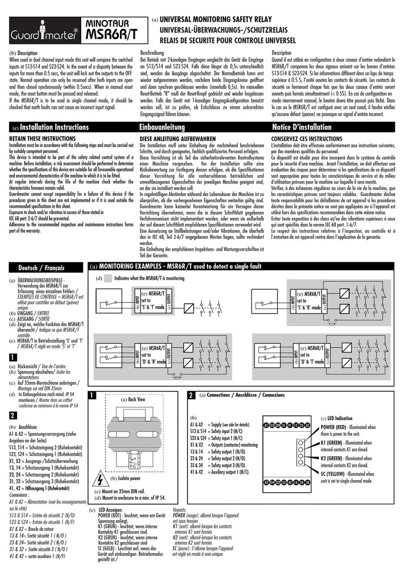
When used in dual channel input mode this unit will compare the switched inputs at S13-S14 and S23-S24. In the event of a disparity between the inputs for more than 0.5 secs, the unit will lock out the outputs to the OFF
state. Normal operation can only be resumed after both inputs are open and then closed synchronously (within 0.5secs). When in manual reset mode, the reset button must be pressed and released.
If the MSR6R/T is to be used in single channel mode, it should be checked that earth faults can not cause an incorrect input signal.
Bei Betrieb mit 2-kanaligen Eingängen verglecht das Gerät die Eingänge an S13/S14 und S23.S24. Falls diese länger als 0,5s unterschiedlich sind, werden die Ausgänge abgeschaltet. Der Normalbetrieb kann erst wieder
aufgenommen werden, nachdem beide Eingangskreise geöffnet und dann synchron geschlossen werden (innerhalb 0,5s). Im manuellen Reset-Betrieb "R" muß der Reset-Knopf gedrückt und wieder losgelassen werded.
Falls das Gerät mit 1-kanaliger Eingangskonfiguration benutzt werden soll, ist zu prüfen, ob Erdschlüsse zu einem unkorrekten Eingangssignal führen können.
Quand il est utilisé en configuration à deux canaux d’entrée redondant le MSR6R/T comparera les deux signaux arrivant sur les bornes d’entrées S13-S14 & S23-S24. Si les informations diffèrent dans un laps de temps
supérieur à 0.5 S, l’unité ouvrira les contacts de sécurité. Les contacts de sécurité se fermeront chaque fois que les deux canaux d’entrés seront ouverts puis fermés simultanément (< 0.5S). En cas de configuration en
mode réarmement manuel, le bouton devra être poussé puis lâché. Dans le cas ou le MSR6R/T est configuré avec un seul canal, il faudra vérifier qu’aucune faute ne provoque un signal d’entrée incorrect.
NOTE: Follow steps 1 to 6 for correct installation. All work should be carried out by suitable competent personnel.
ANMERKUNG: Zwecks korrekter Installation Schritte 1 bis 6 abarbeiten. Alle Arbeiten sind von qualifiziertem Elektro-Personal auszuführen.
NOTE: Suivre les étapes 1 à 6 pour une installation correcte. Cette installation doit être sous la responsabillité d'une personne compétente.
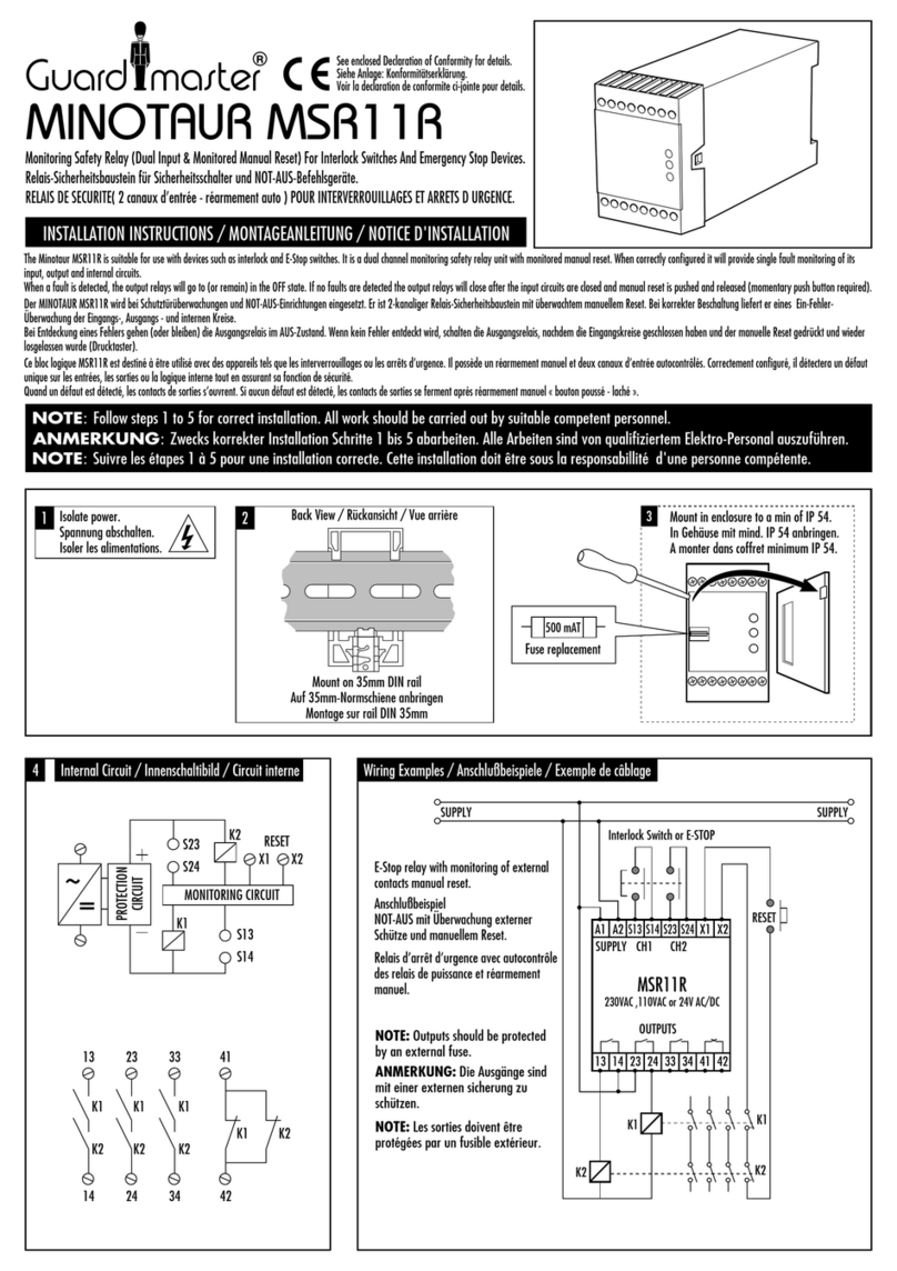
Isolate power.
Spannung abschalten.
Isoler les alimentations.
13
R
T
D
S
500 mAT
Fuse replacement
Mount in enclosure to a min of IP 54.
In Gehäuse mit mind. IP 54 anbringen.
A monter dans coffret minimum IP 54.
2
4 Internal Circuit / Innenschaltibild / Circuit interne Wiring Examples / Anschlußbeispiele / Exemples de câblage
R/T switch -
R (UP) = Manual reset
T (DOWN = Auto reset
S/D switch -
D (UP) = Dual channel.
S (DOWN) = single channel.
For single channel input the S/D switch
should be set to S and inputs S13 - S14
are not used.
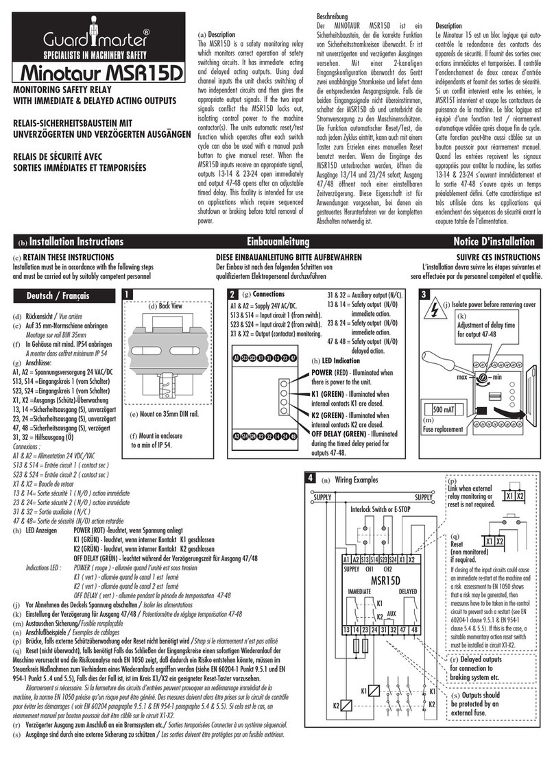
NOTE: The unit will failsafe if terminals
S13 - S14 are simply linked in either S or D mode.
Bei 1-kanaliger Betriebsweise den
S/D-Schiebeschalter auf "S" stellen. Eingänge
S13/S14 werden nicht benutzt.
Pour l'utilisation en canal unique d'entrée, choisir
S & ne pas raccorder S13-S14.
NOTE: L'unité est en défault si S13-S14 sont
simplement reliés en mode S ou D.
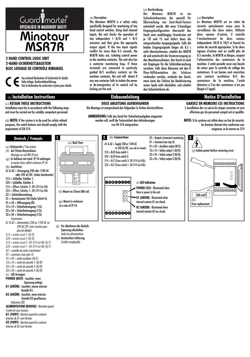
Mount on 35mm DIN rail.
Auf 35mm-Normschiene anbringen.
Montage sur rail DIN 35mm.
X1
S23
S24
S13
S14
K1
13
14
TEST/RESET
X2
A1 A2
SUPPLY SUPPLY
S13 S14 S23 S24
X1 X2
13 14 23 24 33
OUTPUTS
SUPPLY CH1 CH2
K1 K1
K2
K2
Interlock Switch or E-STOP
Interlock Switch or E-STOP control
with Monitoring of External Relays
with Monitored Reset.
Anschlußbeispiel
Schutztürüberwachung oder NOT-AUS
mit Überwachung externer Schütze
und manuellem Reset.
Relais d'arrêt d'urgence avec
autocontrôle des relais de puissance et
réarmement manuel.
NOTE: Outputs should be protected
by an external fuse. In single channel
mode S14 is to be used for earthing.
Anmerkung: Die Ausgänge sind mit
einer externen Sicherung zu schützen.
Bei 1-kanaliger Betriebsweise ist Klemme 14
als Schutzleiter anschluß zu benutzen.
NOTE: Les sorties doivent être
protégées par un fusible extérieur.
Pour le mode d'un canal simple S14
doit être utilisé pour la masse de terre.
MSR6R/T
230VAC ,110VAC or 24V AC/DC
34 41 42
Back View / Rückansicht / Vue arrière
K2
23
24
33
34
41
K1 K2
K1 K1 K1
K2 K2 K2
42
MONITORING CIRCUIT
PROTECTION
CIRCUIT
~
=
EN 60204-1, EN 954-1, EN 292.
24 VAC/DC or 110 VAC or 230 VAC.
< 4 VA.
Normally closed contactor loop.
2 Normally Open switches (guard open).
500 mAT replaceable supply fuse.
R/T selector and S/D selector.
3 N/O and 1 N/C TUV approved.
3 A / 250 VAC / 1000 VA at COSØ = 1.
10 mA / 10 V.
5 A Quick acting on AC.
2.5 Quick acting on DC.
Red = Power ON.
Green = K1 closed.
Green 2 = K2 closed.
Yellow = single channel mode
< 50 m Sec.
2500 V.
-10°C to +55°C.
III.
90 % at + 50°C.
IP 40 DIN 0470.
IP 20 DIN 0470.
1 x 2.5mm
2
stranded with sleeves
stripped 8mm, 1 x 4mm
2
solid
conductor.
Plus-minus terminal screws M3.5
Box terminal with wire protection.
510g.
Red Polycarbonate.
C in accordance with VDE 0110.
35 mm DIN Rail.
In single channel mode
S14 is to be used for earthing
Conforms to:
Power supply:
Power consumption:
X1-X2 Contactor monitor loop:
Safety inputs:
Internal fuse:
Internal switches:
Relay outputs:
Utilisation Cat. (AC):
Min. switched current/voltage:
Max. output fuse:
Indication LED 1:
LED 2:
LED 3:
LED 4:
Max. drop out time:
Impulse withstand voltage:
Operating temperature:
Contamination level:
Humidity:
Degree of Enclosure protection:
Terminal isolation:
Max. conductor size:
Terminals:
Weight:
Material and colour:
Installation group:
Fixing details:
Note:
EN 60204, EN 292, EN 954-1.
24 VAC /DC ou 110 VAC ou 230 VAC.
< 4 VA.
Boucle N/C - réarmement manuel.
2N/C (protecteur fermé).
500 mAT remplaçable.
3 N/O & 1 N/C approuvé TUV.
3A/ 250 VAC / 1000 VA à Cos§ = 1.
10 mA / 10V.
5 A action rapide pour AC
2.5 A action rapide pour DC.
LED 1:Rouge = alimentation ON
LED 2: Vert 1= K1 fermé
LED 3: Vert 2= K2 fermé
LED 4: Jaune= Configuration 1 canal.
< 50 mS.
Impulsions 2500V.
-10°C à + 55°C.
III.
90% à + 55°C.
IP40 DIN 0470.
IP 20 DIN 0470.
1 X 2.5 mm
2
avec enveloppe 8 mm
2
/ 1 X 4 mm
2
industriel.
+/-, Vis imperdable M3, protection câble.
16 bornes / P=120 / H= 73 / L=45.5mm.
510 grs.
Polycarbonate rouge.
C en accord avec VDE 0110.
Rail DIN 35 mm.
Pour le mode d'un canal simple S14
doit être utilisé pour la masse de terre.
Conforme aux normes:
Alimentation:
Consommation:
Boucle de retour X1-X2:
Entrées de sécurité:
Fusible interne:
Relais de sorties:
Catégorie d’utilisation (AC):
Coupure Min. Courant / tension:
Fusible sortie Max.:
Indication:
Temps de réponse Max:
Résistance tension:
Température d’utilisation:
Niveau de contamination:
Humidité:
Indice de protection du boîtier:
Indice de protection des bornes:
Diam. Des conducteurs max:
Bornes:
Boîtier:
Poids:
Matériel et couleur:
Groupe d’installation:
Fixation:
Note:
DIN EN 60204/VDE 0113, DIN EN 292.
Schnellbefestigung auf Normschiene,
16 Klemmen, 73 x 45 x 120mm.
Polycarbonat, rot.
35mm DIN-Hutschiene.
Entfällt (Einbaugerät nach E-DIN 50178).
Schraubanschlüsse für 2 x 1,5mm
2
einschließlich Aderendhülsen; max.
Länge der abisolierten Anschlußleitungen
8mm.
Anschlüsse IP 20, Gehäuse IP 40.
Max. 90% bei +55°C.
Oben: Auto/manueller Reset R/T
Unten: 1-/2-kanaliger Eingang S/D.
1: Rot = Betriebsspannung
2: grün = Ausgangsrelais 1
3: grün = Ausgangsrelais 2
4: gelb = 1-kanaliger Eingang.
24 VAC/DC oder 110/230 VAC
(umschaltbar).
< 4 VA.
500 mAT (austauschbar).
1 oder 2 Öffnerkontakte
(S13/S14, S23/S24).
Brücke oder Schütz-Hilfskontakt (X1/X2).
3 Schließer (13/14, 23/24, 33/34).
1 Öffner (41/42); nur für Meldezwecke.
AC-15; 3 A/250 VAC; DC-13: 3 A/24 VDC.
Typ. 50 ms.
ll nach DIN VDE 0110.
3 nach DIN VDE 0110.
-10°C bis +55°C.
510g.
Bei 1-kanaliger Betriebsweise ist Klemme 14
als Schutzleiter anschluß zu benutzen.
Entspricht den Normen:
Gehäuse:
Gehäusematerial:
Montage:
Schutzklasse:
Anschlüsse:
Schutzart:
Feuchtigkeit:
Interne Schalter:
LED-Anzeige:
Betriebsspannung:
Leistungsverbrauch:
Interne Sicherung:
Eingang:
Test/Reset:
Freigabeausgänge:
Zusatzausgang:
Gebrauchskategorie Ausgänge:
Abfallzeit:
Überspannungskategorie:
Verschmutzungsgrad:
Betriebstemperatur:
Gewicht:
Anmerkung:
Drawing No. 23577
Issue No. 1
change No. 12093
35MM DIN RAIL MOUNTING
45.5
73.0
120
R
T
D
S
5 6
Replace Cover.
Deckel wieder aufsetzen.
Remettre le couvercle
sans forcer.
Connect power - Check
operation before
allowing operator use.
Spannung anschließen. Vor
Inbetriebnahme auf korrekte
Funktion überprüfen.
Connectez l'alimentation -
Contrôlez le bon
fonctionnement des sécurités
avant la mise en service
pour la protection des
opérateurs.
NOTE: In th event of an internal fault the unit must be returned to Guardmaster.
ANMERKUNG: Bei einem internen Fehler das Gerät bitte an Guardmaster zurückschicken.
NOTE: Dans le cas d'un dysfonctionnement interne, le bloc logique doit être retourné chez Guardmaster.
TECHNICAL SPECIFICATIONS TECIFICATIONS TECHNIQUES
TECHNISCHE DATEN
PART OF THE E.J.A. ENGINEERING GROUP
Guardmaster Ltd.
Hindley Green Ind. Est. Wigan, England WN2 4HR
Tel: 01942 255166 (Int: +441942 255166)
Fax: 01942 523259 (Int: +44 1942 523259)
Guardmaster Sicherheitstechnik GmbH.
Am Stadion 15, 42897 Remscheid, Deutschland
Telefon: (02191) 9685-0 Telefax: (02191) 9685-20
Guardmaster France.
274 Rue Jules Ferry, 95360 Montmagny.
Téléphone: (01) 39 83 60 60
Télécopie: (01) 39 83 28 00
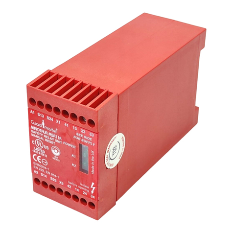
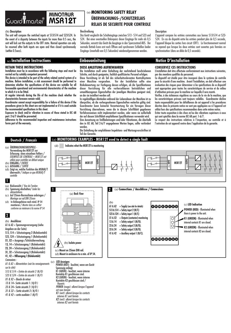
Other Guard master Relay manuals

Guard master Minotaur MSR11R User manual

Guard master

Guard master Minotaur MSR11R User manual

Guard master MINOTAUR MSR12T User manual

Guard master

Guard master MINOTAUR MSR12T User manual

Guard master MINOTAUR MSR11R User manual

Guard master

Guard master MINOTAUR MSR11R User manual

Guard master Minotaur MSR15D User manual

Guard master

Guard master Minotaur MSR15D User manual

Guard master MINOTAUR MSR6R/T User manual

Guard master

Guard master MINOTAUR MSR6R/T User manual

Guard master Minotaur MSR7R User manual

Guard master

Guard master Minotaur MSR7R User manual

Guard master MINOTAUR MSR16R/T User manual

Guard master

Guard master MINOTAUR MSR16R/T User manual

Popular Relay manuals by other brands

Eaton ESR5-VE3-42 manual

Eaton

Eaton ESR5-VE3-42 manual

Pilz PNOZ s9 operating manual

Pilz

Pilz PNOZ s9 operating manual

Eaton Compressor EMT6 Instruction leaflet

Eaton Compressor

Eaton Compressor EMT6 Instruction leaflet

Siemens SIRIUS 3RF22 Series operating instructions

Siemens

Siemens SIRIUS 3RF22 Series operating instructions

Pilz PNOZ s30 operating manual

Pilz

Pilz PNOZ s30 operating manual

Pilz PNOZ X2 operating instructions

Pilz

Pilz PNOZ X2 operating instructions

Tense RGM-12S user manual

Tense

Tense RGM-12S user manual

Basler BE1-50/51B-232 instruction manual

Basler

Basler BE1-50/51B-232 instruction manual

Crydom DC60 Series Installation sheet

Crydom

Crydom DC60 Series Installation sheet

2N Helios IP Security Relay How to use

2N

2N Helios IP Security Relay How to use

Alstom MX3IPG2A Technical manual

Alstom

Alstom MX3IPG2A Technical manual

Siemens SIRIUS 3RP15 operating instructions

Siemens

Siemens SIRIUS 3RP15 operating instructions

ABB SPAS 348 C User manual and technical description

ABB

ABB SPAS 348 C User manual and technical description

Thytronic NA30 manual

Thytronic

Thytronic NA30 manual

Kyongbo Electronics GDR-C01 manual

Kyongbo Electronics

Kyongbo Electronics GDR-C01 manual

Omron F3SP-T01 manual

Omron

Omron F3SP-T01 manual

Seg MRM3 manual

Seg

Seg MRM3 manual

Pilz PNOZ 16SP operating instructions

Pilz

Pilz PNOZ 16SP operating instructions

manuals.online logo
manuals.online logoBrands
  • About & Mission
  • Contact us
  • Privacy Policy
  • Terms and Conditions

Copyright 2025 Manuals.Online. All Rights Reserved.