GULLCO GP-200 User manual

Revised: July 4, 2018 GD-044-T
WELDING
POSITIONER
(USINGGULLCOGSP‐1100
SERIESCONTROLS)
MODELS:
GP-200, GPP-200
TECHNICAL
MANUAL
Website: www.gullco.com
Distributed b
y
:


1
SAFETY INSTRUCTIONS
Although the Gullco welding positioner is manufactured for safe and dependable operation, it is
impossible to anticipate those combinations of circumstances, which could result in an accident. An
operator of the welding positioner is cautioned to always practice "Safety First" during each phase
of operation, setup and maintenance.
Read and understand the whole Operating Instructions manual (including this Technical manual
complete with the supplementary GSP-1100 Control Manual, “GD-084”) before operating or
performing service of this equipment. Become familiar with the machines operation, applications
and limitations. Keep the operation manual in a clean and readily available location.
This equipment is normally used to automate / semi-automate welding or cutting processes. These
processes usually have any combination of the following; bright and hot arcs, flying sparks, fumes,
ultraviolet and infrared radiated energy, hot work-pieces, compressed gases, etc.. The onus is on
the operator of this equipment to know, understand and follow all the safety precautions associated
with the process being used.
A careless operator invites troubles, and failure to follow safety practices may cause serious injury
or even death. Important safety precautions are given in the following:
Electrical Shock Prevention
Do not use this equipment in damp or wet locations.
Do not expose this equipment to rain.
Do not touch electrically live parts or electrode with skin or wet clothing.
Insulate yourself from the work and ground.
Never carry this equipment by the cables or pull the cables to disconnect from the receptacle.
Keep all cables from heat, oil and sharp edges.
Inspect all cables periodically and replace if damaged.
Inspect the security of all cables periodically and repair if loose.
Disconnect the power cord when not in use.
Disconnect the power cord positively to prevent electrical shock before repair and service of the
equipment.
Bodily Injury Prevention
Do not wear loose clothing, jewellery or loose, long hair which may get caught into automatic systems
or moving parts.
Keep equipment (especially lifting handles) dry, clean and free from oil & grease.
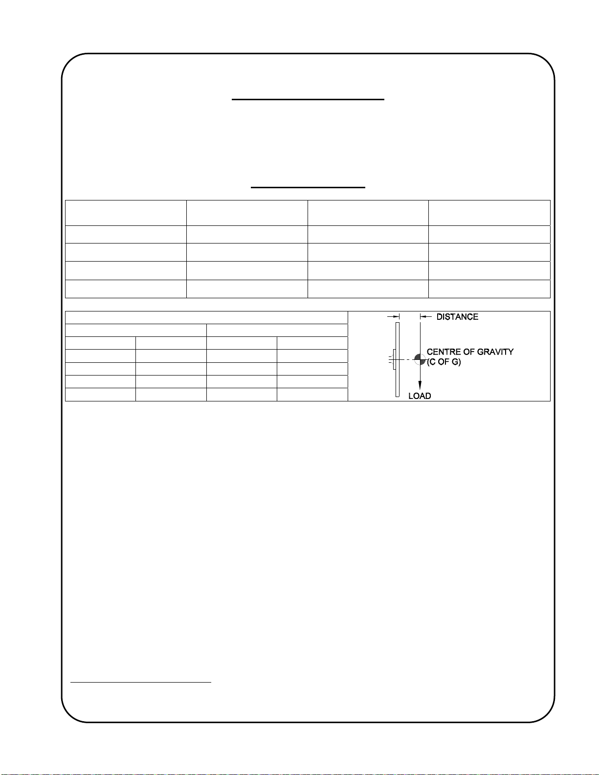
Ensure that the positioner is well secured to the bench, tabletop, etc., to prevent it from tipping over
when subjected to over hung loading.
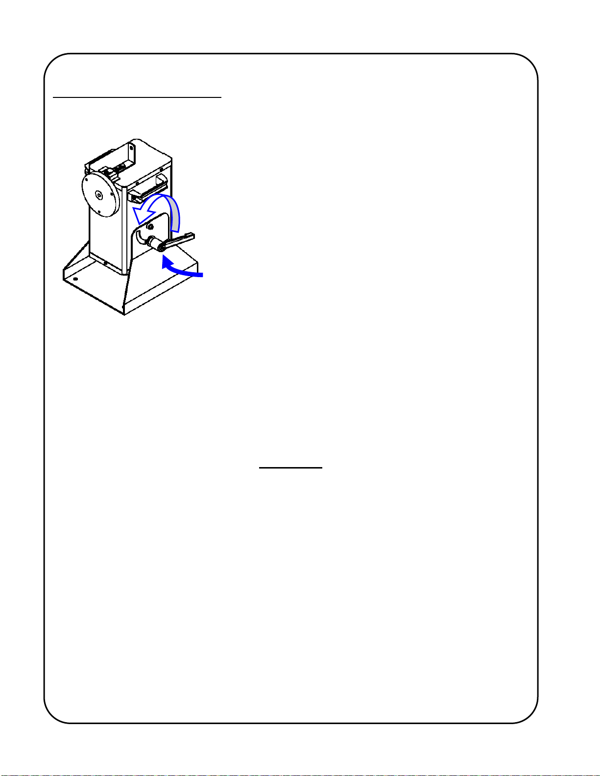
Never loosen the tilt-locking lever, nor try to tilt the rotary welding table, when there is a load mounted
to the table generating large radial moments.
Keep hands away from the rotary table when it is in motion, or when there is the slightest possibility of
motion.
Wherever possible, avoid mounting devices, etc., that protrude from the rotating mass, and pose
possible pinch-points.
Make certain that work-piece/mounting device protrusions will not strike the floor, positioner frame or
any other object during rotation.
There should only ever be one (1) operator working at the machine at any given time.
Do not operate this equipment if drowsy from medication or fatigue.
Do not lift the machine with heavy accessories or cables attached and only lift using adopted safe
lifting standards and practices.

2
SAFETY PRECAUTIONS
The following cautionary/warning labels are attached to each welding positioner:-
The adjacent label pictorially represents the following:
Warning:-
Do not loosen the tilt clamp lever when there is a load
applied to the table. This may result in an unexpected
radial movement!
The above label pictorially represents the following:
Warning:-
Do not start, operate or service this equipment until you have read and
understood the operator’s manual(s)!”
IMPORTANT
READ THIS BEFORE OPERATING THE WELDING POSITIONER
When used with electric arc welding or cutting equipment, ensure that an adequate and well-
maintained power return path is provided with good electrical contact. Failure to do so may result in
the welding/cutting current passing through the Positioner and damaging the wiring and electrical
components.
Important information regarding safety and operation of the “GSP-1100” motor control used in the
Positioner is contained in a supplemental manual attached at the end of this manual. It is equally
important to read, understand and apply the information contained within that manual. The
supplemental manual (GD-084) has a title “Technical Information For The Gullco “GSP-1100”
Microprocessor Based Motor Control”, and it’s pages are numbered with a prefix of “T-“.
ALL THE SAFE PRACTICES AND PRECAUTIONS MAY NOT BE GIVEN IN WRITING. SOME
ARE BASED ON COMMON SENSE, BUT OTHERS MAY REQUIRE TECHNICAL
BACKGROUND TO EXPLAIN.

3
WELDING POSITIONER
This parts list covers the operation and maintenance requirements of the following Gullco welding
positioners:
GP-200-M, GP-200-H, GPP-200-M & GPP-200-H
SPECIFICATIONS
MODEL 0.27 – 4.62962 RPM 0.75 – 12.5000 RPM GAS
PURGE SYSTEM†
GP-200-M
GP-200-H
GPP-200-M
GPP-200-H
OVERHUNG LOAD RATING, TABLE VERTICAL
Distance (C of G) Load
Inches mm. Lbs. Kgs.
3 76 150 68
6 152 75 34
9 229 50 22.7
12 305 37.5 17
Stand alone weight: 53 Lbs. [24 Kg.]
Rotational Torque: 108 in.lbs [124 Kg.cm]
Vertical Table loading: 450 in.lbs [518 Kg.cm] from face.
Horizontal Table Loading: 300 lbs. [136 Kg.cm]
Supply voltage: Either 42, 115 or 230 VAC, single phase, 50/60 Hz., 200 watts.
Tilt angle: Infinitely variable from 0 to 90 degrees (horizontal to vertical).
Welding ground: Sprung loaded, rotary ground on the underside of the table.
Drive motor: 24 VDC permanent magnet gear motor.
Complies with: C.S.A. & NRTL/C and C.E. regulations.
†The gas purge system allows pre-weld gas purging by providing a path for the gas through a rotary gas
coupling and through the center of the table spindle.

4
GENERAL DIMENSIONS

5
INSTALLATION
ELECTRICAL CONNECTION
WARNING! Ensure proper AC earth grounding of the Gullco welding positioner and all auxiliary
equipment (where applicable), before applying power. Failure to do so may
invalidate the Gullco Warranty.
WARNING! Before connecting the welding positioner to a power source (receptacle, outlet, etc.,)
be sure that the voltage supplied is the same as that specified on the nameplate of
the positioner. If in doubt, DO NOT PLUG IN THE WELDING POSITIONER. Copies
of the possible nameplates are shown below:
As the colours of the wires in the mains lead of this equipment may not correspond with the
coloured markings identifying the terminals in your plug, proceed as follows:
The Green & Yellow or Green wire must be connected to the terminal in the plug which is
allocated for “Earth” / “Ground”.
The Blue or White wire must be connected to the terminal that is allocated for “Neutral”.
The Brown or Black wire must be connected to the terminal that is allocated for “Live”.
230V Equipment must be installed in accordance with CEC, NEC or other applicable electrical
code.
WARNING! Ensure that the weld ground is properly attached to the ground bracket on the
positioner. A poor welding ground circuit will cause the weld ground to pass through
the positioner, causing damage to the motor control, cables, drive system and the
main spindle bearings. This will invalidate the Gullco warranty.

6
MECHANICAL INSTALLATION
WARNING! Check to ensure that no parts have become loose during transportation.
The Gullco positioner is equipped with handles for portability. The
weight of the positioner is evenly distributed around the handles
when tilted and locked in the upright position (as shown adjacent).
Lifting the positioner with additional equipment attached (resulting
in uneven weight distribution), cables attached, or with the
positioners tower in any other position than upright and firmly
locked, may present a hazard. Therefore we recommend that
care and consideration should be given to removing uneven loads
and /or any additions that may make the total weight of the
equipment too heavy or awkward to be comfortably lifted.
WARNING! Never disengage the tilt locking lever, when there
is a possibility that this action may result in uncontrollable or
unsafe radial motion of the positioner tower.
Bolt the welding positioner to a fixed table using four (4), 3/8" or 10mm bolts (not supplied). The
center distances of the positioners pre-drilled mounting boltholes are 8" [20.3 cm] wide by 10" [25.4
cm] long.
Check that the welding ground block on the underside of the spindle flange is correctly located and
well seated.
Depending on any optional accessories that may have been supplied with the unit, further
installation may be required. This typically consists of any combination of simple mechanical
erection and simple cable connection (usually through multi-pin connectors).
LOADING
Before mounting any load to the rotary table, the tilt locking adjustable lever should be tested for
tightness. When loading the work piece onto the table, take account of the weight, centroid
eccentricity and centroid height of both the work piece and all clamping fixtures. When the work
piece is large and its weight is one sided at the peripheral portion, inertia start and stop is severe
and can cause an overload situation. Wherever possible, counterbalance weights should be used
to reduce this stress. Take into consideration the additional weight and distribution of the
counterbalance.
WARNING! Lower work pieces onto the turntable gently. Impact and shock loads are many
times greater than the "dead-weight” of the work-piece. Dropping loads onto the
table can result in damage!
WARNING! Do not use impact or shock techniques to clamp and unclamp self-centering grippers
mounted to the positioner turntable. The shock will be transferred to the drive
system resulting in damage!

7
MAINTENANCE
The Gullco welding positioner is a heavy duty, robust piece of equipment, and under normal
conditions, it will give you years of trouble free service, if it is operated within the limits of its
expected use and if the following maintenance points are adhered to:
Clean all excess dust, spatter, slag etc. from the positioner regularly. Do not allow any foreign
material to impede operation. Pay particular attention to the following paragraph regarding
inspection.
INSPECTION
The welding ground should be inspected for a secure, clean electrical contact from the welding
power source to the grounding bracket of the positioner before the start of each new day of welding.
The fasteners of the positioner grounding assembly should be inspected for security. A visual
check of the grounding block, springs and ground strap should be performed to ensure that the
ground block is seating flat against a clean, spindle flange and that there are no signs of obvious
damage occurring.
Frequent inspections should be performed with respect to the stability and rigidity of the positioner
mounting. Also, the drive sprockets, chain and spindle bearings should be inspected for signs of
wear and replaced if necessary.
The tension of the drive chain should be inspected and adjusted as necessary. The drive chain
tension is adjusted by loosening off the four (4) motor mounting button headed cap screws (item#
37 in drawing GP-200 & item# 38 in drawing GPP-200). Then loosen the jam nut and adjust the
motor tensioning screw as required (items # 31 & 43 in drawing GP-200 & items 32 & 44 in drawing
GPP-200). Once the desired tension has been set, re-tighten the jam nut and the four (4) motor
mounting screws.
WARNING! A small amount of radial backlash on the spindle is inherent in the design of the
Positioner. Do not over-tension the drive chain in an attempt to remove this backlash
as this will cause the motor to overload and possibly result in gear-motor failure and
will invalidate the Gullco warranty.
The tachometer feed-back encoder sensor assembly located on the back of the motor should be
inspected for dirt accumulation and cleaned where necessary. It is common for the armature shaft
of a fatiguing motor to develop excessive axial float. This float sometimes causes the tachometer
feed-back sensor wheel to rub on one of the encoder sensor faces, causing damage and failure.
Check that the sensor disk is located centrally within the slot of the encoder sensor when the
armature shaft is pressed in and pulled out. Adjust as necessary. The frequency of this inspection
should increase with the accumulated use and or workload of the gear-motor.
At least once per year, the equipment should be taken out of service, stripped down and all moving
parts should be cleaned, greased and inspected for wear and damage. All cables must be
inspected for breaks and abrasion and must be well secured. All damaged and worn parts should
be replaced, using genuine/authorized replacement parts only. All fastening devices should be
inspected for tightness.
NOTE: These inspections should be performed with greater frequency if conditions and usage
requires.

8
STORAGE
The Gullco welding positioner should be kept in a dry environment with no possibility of impact or
damage due to stacking of heavy objects on top of the equipment.
SHIPPING
When shipping the Gullco welding positioner, the rotary table should be locked in the horizontal
plane and the mounting table removed and safely packaged. There should be sufficient room
around the perimeter of the shipping box to allow packing to be placed to help protect susceptible
parts from being damaged in shipping. If possible, the whole positioner should be bolted to a flat
piece of wood.
ACCESSORIES
GP-200-024 Run/Stop footswitch assembly for manual operation. This kit provides a run/stop
footswitch; a footswitch guard cover; a connecting control cable; and strain relief
glands. When activated, the footswitch will provide a run signal to the control.
GP-200-025 Variable Speed footswitch assembly for manual operation. This kit provides a
run/stop/variable speed footswitch; a footswitch guard cover; a connecting control
cable; and strain relief glands. When activated, the footswitch will provide a run
signal to the control and allow regulation of the rotational speed via the
compression of the footswitch pedal.
GP-200-023 Forward/Stop/Reverse footswitch assembly for manual operation. This kit
provides directional footswitches; a footswitch guard cover; a connecting control
cable; and strain relief glands. When activated, the footswitch will provide a run
signal and a rotary direction signal to the control.
GP-200
GPP-200
GP-200-016 (GP-200 & GP-200)

9
GP-200-016 12” [305 mm] Diameter mounting table. This round mounting table is used to
facilitate direct mounting of components or fixtures and provides six (6) radial
mounting slots and various three (3) hole pitch circle bolt patterns. The mounting
table is quickly and easily mounted on the positioner spindle flange.
WPG-250 Gullco Self-Centering Welding Grippers are quickly and easily mounted on the
positioner spindle flange. They are slim but rugged, weighing only about half of
that of a standard chuck, minimizing reduction in positioner capacity. A single
lever provides smooth, positive, self-centering open/close action.
External clamping range = 0.38" [10mm] to 11.25" [286mm]
Internal clamping range = 4.25" [108mm] to 15" [381mm]
Weight 20 Lbs. [9 Kg.]
KR-1000 CSB A free standing support and cutting torch holder assembly. 1-1/8" [28.6mm]
square rack arms and rack boxes provide 11-1/2" [292.1mm] of vertical
adjustment and 10-1/2" [266.7cm] of horizontal adjustment. Supplied with swivel
mounted, standard rack-type cutting torch holder.
KR-2000 CSB Same as above, except uses 1-1/2" [38.1mm] rack arms and rack boxes and
provides 7-1/2" [190.5mm] of vertical and 6-1/2" [165.1mm] of horizontal
adjustment.
KR-1000 WSB A free standing support and welding gun holder assembly. 1-1/8" [28.6mm]
square rack arms and rack boxes provide 11-1/2" [292.1mm] of vertical
adjustment and 10-1/2" [266.7mm] of horizontal adjustment. Supplied with swivel
mounted, adjustable gun holder assembly.
KR-2000 WSB Same as above, except uses 1-1/2" [38.1mm] rack arms and rack boxes and
provides 7-1/2" [190.5mm] of vertical and 6-1/2" [165.1mm] of horizontal
adjustment.
NOTE: The above cutting torch and welding gun support assemblies can be, and often
are, equipped with one (1) or two (2) Gullco motorized rack arms controlled by a
remote joystick pendant. Ask your local Gullco representative for further details.
ALSO AVAILABLE:
Gullco frequently designs and manufactures custom welding systems, often utilizing the welding
positioner. These systems normally use some, or all of the following; a programmable logic control,
a programmable operator interface (that allows the user to easily adjust any of the timed and
counted preset values etc.), pneumatic or motorized slide/slides, interfacing with welding/cutting
equipment, external safety devices, auxiliary process equipment etc. Your local Gullco
representative would welcome the opportunity to discuss how we may assist in automating your
specific application.

1
0
WELDING POSITIONER PARTS BREAKDOWN
DRAWING GP-200
S
p
ecif
y
model and serial numbers when orderin
g
p
arts.

11
WELDING POSITIONER PARTS BREAKDOWN
DRAWING GP-200

12
WELDING GAS PURGE POSITIONER PARTS BREAKDOWN
DRAWING GPP-200
S
p
ecif
y
model and serial numbers when orderin
g
p
arts.

13
WELDING GAS PURGE POSITIONER PARTS BREAKDOWN
DRAWING GPP-200

14
ITEM PART No. DESCRIPTION QTY
1 GP-200-004 BOTTOM COVER 1
2 GK-165-134 FUSE HOLDER ASSEMBLY 1
GK-191-P-022 POWER ON/OFF SWITCH 1
GK-191-P-050 ON/OFF NAME PLATE 1
GK-191-P-019-A 42V TRANSFORMER
GK-191-P-019-B 115V TRANSFORMER
GK-191-P-019-C 230V TRANSFORMER
5 GK-191-P-218 TRANSFORMER MTG. PAD 2
6 GK-191-P-105 TRANSFORMER MTG. PLATE 1
7 GK-191-P-020 BRIDGE 1
8 GK-191-P-062 CAPACITOR 1
9 GK-191-P-063 CAPACITOR CLAMP 1
10 GK-111-068 No. 10 WASHER 3
11 GK-135-057 No. 10-32UNF LOCK NUT 5
GK-165-098 5A SLOW BLOW FUSE(42V MODELS)
GK-165-099 2.5A SLOW BLOW FUSE(115V MODELS)
GK-165-097 1.25A SLOW BLOW FUSE(230V MODELS)
13 GK-129-012 No. 10 INTERNAL STAR WASHER 1
14 GK-191-P-103 DISCHARGE RES. WIRING HARNESS 1
15 GK-191-P-127 H.F. CAPACITOR WIRING HARNESS 1
16 GK-191-P-128 POWER INTERFACE HARNESS 1
17 GK-191-P-140 DC SUPPLY WIRING HARNESS 1
3
41
12 1
POSITIONER POWER SUPPLY ASSEMBLY PARTS BREAKDOWN
DRAWING GP-200-018

1
5
ITEM PART NO. DESCRIPTION QTY
GP-200-011 POSITIONER MOTOR ASSEMBLY
(
200:1
)
1 GP-200-131 24VDC GEARMOTOR 200:1 1
2 GK-191-P-03
5
ENCODER SENSOR, INCLUDING WIRING & CONNECTO
R
1
3 GK-191-P-038 ENCODER DISC 1
4 GK-112-060 #4-40UNC x 1/4" ROUND HEAD SCREW 2
5
GK-106-063 #4-40UNC x 3/16" SET SCREW 3
6 GK-148-019 STRAIN RELIEF GLAND 1
7 GK-190-111 ENCODER COVER 1
8 GK-105-086 #8-32UNC x 7/8" FLAT HEAD SOCKET CAP SCREW 2
9 GK-156-003 2 CIRCUIT MALE CONNECTOR HOUSING 1
10 GK-156-016 FEMALE TERMINAL 2
GP-200-01
5
POSITIONER MOTOR ASSEMBLY
(
540:1
)
1 GP-200-133 24VDC GEARMOTOR 540:1 1
2 GK-191-P-035 ENCODER SENSOR, INCLUDING WIRING & CONNECTOR 1
3 GK-191-P-038 ENCODER DIS
C
1
4 GK-112-060 #4-40UNC x 1/4" ROUND HEAD SCREW 2
5 GK-106-063 #4-40UNC x 3/16" SET SCREW 3
6 GK-148-019 STRAIN RELIEF GLAND 1
7 GK-190-111 ENCODER COVE
R
1
8 GK-105-086 #8-32UNC x 7/8" FLAT HEAD SOCKET CAP SCREW 2
9 GK-156-003 2 CIRCUIT MALE CONNECTOR HOUSING 1
10 GK-156-016 FEMALE TERMINAL 2
POSITIONER MOTOR ASSEMBLY PARTS BREAKDOWN
DRAWING GP-200-011 & GP-200-015

1
6
ITEM PART No. DESCRIPTION QTY
1 KR-179-113 FOOT SWITCH COVER 1
2 KR-179-115 NON-SLIP FOOT SWITCH PAD 1
3 KR-179-122 FOOT SWITCH 1
4 GK-125-055 #8-18 x 3/8" TAP SCREW 2
5 GK-135-057 #10-32UNF LOCK NUT 1
6 KR-190-112 CABLE STRAIN BRACKET 1
7 GK-112-065 #10-32UNF x 3/8" ROUND HEAD SCREW 1
8 GK-148-014 DD STRAIN RELIEF PIGTAIL 1
9 RM-111-110 4 CONDUCTOR SHIELDED CABLE 10'-10"
10 GK-148-017 STRAIN RELIEF LOCK NUT 1
11 GK-148-015 STRAIN RELIEF 7/8"
Ø
1
12 GK-156-032 WIRE CONNECTOR 3 POSITION FEMALE 1
13 GK-156-017 WIRE CONNECTOR CRIMP TERMINAL 3
14 GK-156-008 #10 RING TERMINAL CRIMP 2
OPTIONAL RUN/STOP FOOTSWITCH PARTS BREAKDOWN
DRAWING GP-200-024
GP-200, GPP-200, GP-300
GP-250, GPP-250 OR GP-350
(
NOT INCLUDED
)

1
7
ITEM PART No. DESCRIPTION QTY
1 GP-200-023-1 FWD/STOP/REV FOOTSWITCH 1
2 RM-111-110 4 CONDUCTOR SHIELDED CABLE 10'-6"
3 GK-148-017 STRAIN RELIEF LOCK NUT 1
4 GK-148-015 STRAIN RELIEF 7/8"Ø 1
5 GK-156-033 WIRE CONNECTOR 4 POSITION FEMALE 1
6 GK-156-017 WIRE CONNECTOR CRIMP TERMINAL 3
7 GK-156-008 #10 RING TERMINAL CRIMP 2
OPTIONAL FORWARD/STOP/REVERSE FOOTSWITCH PARTS BREAKDOWN
DRAWING GP-200-023
GP-200, GPP-200 OR GP-300
(NOT INCLUDED)

1
8
ITEM PART No. DESCRIPTION QTY
1 GP-150-020-A VARIABLE SPEED FOOT SWITCH 1
2 RM-111-110 4 CONDUCTOR SHIELDED CABLE 10'-6"
3 GK-148-017 STRAIN RELIEF LOCK NUT 1
4 GK-148-015 STRAIN RELIEF 7/8"
Ø
1
5 GK-156-032 WIRE CONNECTOR 3 POSITION FEMALE 1
6 GK-156-017 WIRE CONNECTOR CRIMP TERMINAL 4
7 GK-156-031 WIRE CONNECTOR 2 POSITION FEMALE 1
8 GK-148-012 STRAIN RELIEF 1
9 GK-156-008 #10 RING TERMINAL CRIMP 2
OPTIONAL VARIABLE SPEED FOOTSWITCH PARTS BREAKDOWN
DRAWING GP-200-025
GP-200, GPP-200 OR GP-300
(NOT INCLUDED)
This manual suits for next models
1
Table of contents
Other GULLCO Welding System manuals
Popular Welding System manuals by other brands

Lincoln Electric
Lincoln Electric VRTEX TRANSPORT+ Operator's manual

Castolin Eutectic
Castolin Eutectic ArcWeld 420i Technical manual

SincoSald
SincoSald NOVAMIG 403 E Instruction manual for installation, use and maintenance

Lincoln Electric
Lincoln Electric Invertec V205 Operator's manual

ESAB
ESAB m3 Plasma EPP-202 instruction manual

ESAB
ESAB HandyPlasma 250 instruction manual