manuals.online logo
Brands
  1. Home
  2. •
  3. Brands
  4. •
  5. Siemens
  6. •
  7. Gateway
  8. •
  9. Siemens SIMATIC FDE Technical Document

Siemens SIMATIC FDE Technical Document

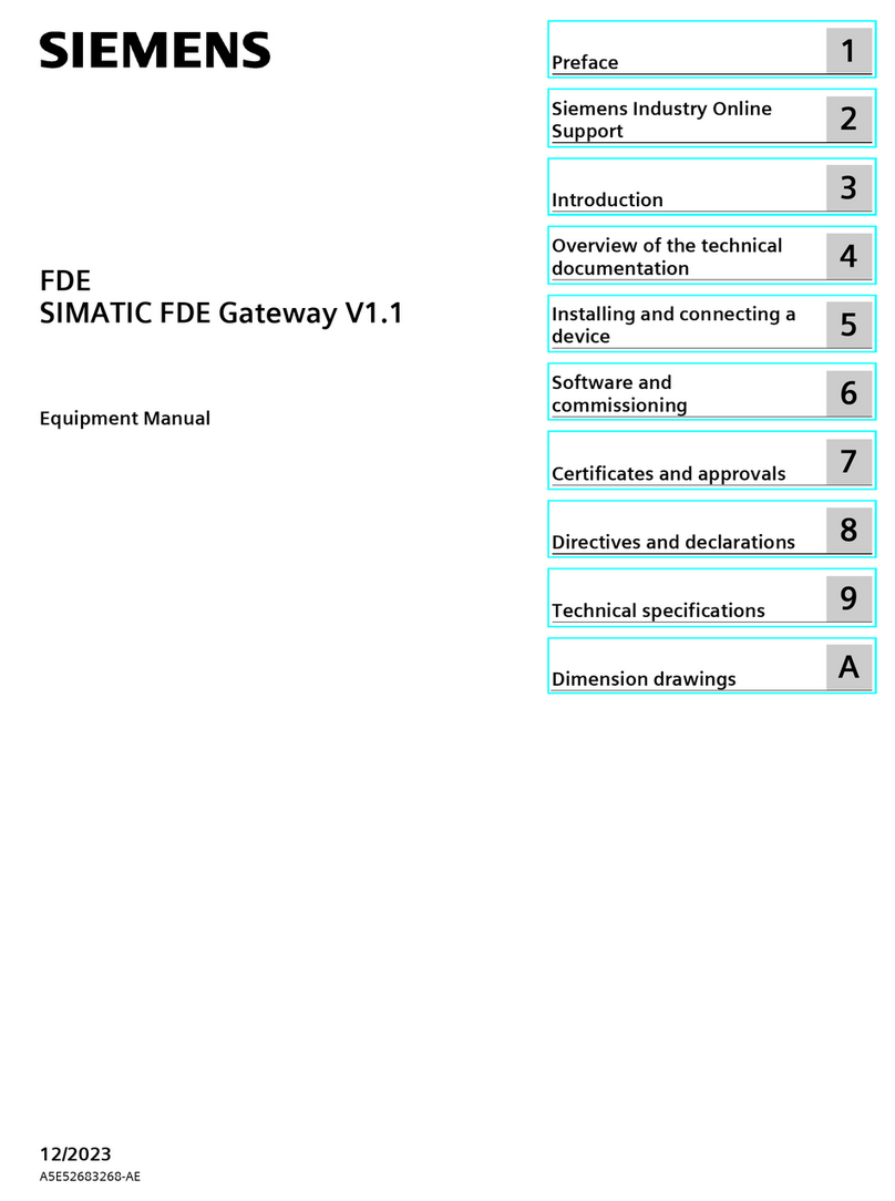
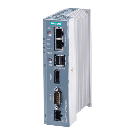
SIMATIC FDE Gateway V1
FDE
SIMA
TIC FDE Gateway V1
Equipment Manual
05/2023
A5E52683268
-AB
Preface
1
Siemens Industry Online
Support
2
Introduction
3
Overview of the technical
documentation
4
Installing and connecting a
device
5
Software and
commissioning
6
Certificates and approvals
7
Directives and declarations
8
Technical specifications
9
Dimension drawings
A
Siemens AG
Digital Industries
Postfach 48 48
90026 NÜRNBERG
GERMANY
A5E52683268-AB
Ⓟ
05/2023 Subject to change
Copyright © Siemens AG 2023.
All rights reserved
Legal information
Warning notice system
This manual contains notices you have to observe in order to ensure your personal safety, as well as to prevent
damage to property. The notices referring to your personal safety are highlighted in the manual by a safety alert
symbol, notices referring only to property damage have no safety alert symbol. These notices shown below are
graded according to the degree of danger.
DANGER
indicates that death or severe personal injury will result if proper precautions are not taken.
WARNING
indicates that death or severe personal injury may result if proper precautions are not taken.
CAUTION
indicates that minor personal injury can result if proper precautions are not taken.
NOTICE
indicates that property damage can result if proper precautions are not taken.
If more than one degree of danger is present, the warning notice representing the highest degree of danger will
be used. A notice warning of injury to persons with a safety alert symbol may also include a warning relating to
property damage.
Qualified Personnel
The product/system described in this documentation may be operated only by personnel qualified for the specific
task in accordance with the relevant documentation, in particular its warning notices and safety instructions.
Qualified personnel are those who, based on their training and experience, are capable of identifying risks and
avoiding potential hazards when working with these products/systems.
Proper use of Siemens products
Note the following:
WARNING
Siemens products may only be used for the applications described in the catalog and in the relevant technical
documentation. If products and components from other manufacturers are used, these must be recommended
or approved by Siemens. Proper transport, storage, installation, assembly, commissioning, operation and
maintenance are required to ensure that the products operate safely and without any problems. The permissible
ambient conditions must be complied with. The information in the relevant documentation must be observed.
Trademarks
All names identified by ® are registered trademarks of Siemens AG. The remaining trademarks in this publication
may be trademarks whose use by third parties for their own purposes could violate the rights of the owner.
Disclaimer of Liability
We have reviewed the contents of this publication to ensure consistency with the hardware and software
described. Since variance cannot be precluded entirely, we cannot guarantee full consistency. However, the
information in this publication is reviewed regularly and any necessary corrections are included in subsequent
editions.
SIMATIC FDE Gateway V1
Equipment Manual, 05/2023, A5E52683268-AB 3
Table of contents
1 Preface ................................................................................................................................................... 5
2 Siemens Industry Online Support.......................................................................................................... 6
3 Introduction ........................................................................................................................................... 7
3.1 Security information ............................................................................................................ 7
3.2 IT security on the northbound side ....................................................................................... 7
3.3 IT security on the southbound side....................................................................................... 8
3.4 Personal data....................................................................................................................... 8
4 Overview of the technical documentation............................................................................................ 9
4.1 SIMATIC products................................................................................................................. 9
4.2 SINAMICS products .............................................................................................................. 9
4.3 SENTRON products............................................................................................................. 11
5 Installing and connecting a device...................................................................................................... 12
5.1 Scope of supply ................................................................................................................. 12
5.2 Information on the software license................................................................................... 12
5.3 Description ........................................................................................................................ 12
5.4 Device design .................................................................................................................... 15
5.5 Analog input and digital input/output................................................................................. 16
5.6 Operating modes and LED display ...................................................................................... 18
5.7 Changing the operating mode ........................................................................................... 19
5.8 Preparing for installation.................................................................................................... 19
5.9 Installing the device........................................................................................................... 21
5.9.1 Mounting instructions........................................................................................................ 21
5.9.2 DIN-rail mounting .............................................................................................................. 22
5.10 Connecting the device ....................................................................................................... 24
5.10.1 Notes for connecting ......................................................................................................... 24
5.10.2 Connecting interfaces to connecting terminal X4 ............................................................... 25
5.10.3 Connecting the power supply............................................................................................. 26
5.10.4 Securing cables.................................................................................................................. 26
5.10.5 Connecting a device to the RS232 interface........................................................................ 27
Table of contents
SIMATIC FDE Gateway V1
4Equipment Manual, 05/2023, A5E52683268-AB
6 Software and commissioning .............................................................................................................. 29
6.1 Establishing a connection to the device.............................................................................. 29
6.2 Device configuration.......................................................................................................... 30
6.3 Network settings ............................................................................................................... 32
6.4 Connectivity settings ......................................................................................................... 35
6.4.1 MQTT settings ................................................................................................................... 36
6.4.2 USS settings ...................................................................................................................... 38
6.4.3 Enable analog & digital input and digital output ................................................................. 39
6.4.4 Activate Modbus TCP (X2).................................................................................................. 42
6.5 MQTT payload examples.................................................................................................... 44
6.6 Date and time settings....................................................................................................... 48
6.7 Factory settings, system upgrade ....................................................................................... 49
6.8 Settings for operation on the BFC Gateway ........................................................................ 51
6.9 Settings for operation on the Industrial Edge device ........................................................... 52
6.10 Settings for operation in MindSphere ................................................................................. 53
7 Certificates and approvals ................................................................................................................... 54
7.1 CE (Industry)...................................................................................................................... 54
7.2 UKCA................................................................................................................................. 54
7.3 RCM Declaration of Conformity for Australia/New Zealand.................................................. 55
7.4 China Compulsory Certificate ............................................................................................. 55
8 Directives and declarations ................................................................................................................. 56
8.1 Overvoltage category......................................................................................................... 56
8.2 Pollution degree for electrical equipment ........................................................................... 56
8.3 Electromagnetic Compatibility industrial area +A1:2011..................................................... 56
8.4 ESD guideline .................................................................................................................... 56
9 Technical specifications....................................................................................................................... 59
9.1 General technical specifications ......................................................................................... 59
9.2 Ambient conditions ........................................................................................................... 62
A Dimension drawings............................................................................................................................ 63
A.1 Dimension drawings .......................................................................................................... 63
SIMATIC FDE Gateway V1
Equipment Manual, 05/2023, A5E52683268-AB 5
Preface
1
The following operating instructions contain all the required information required for
commissioning and operating a device from the SIMATIC family.
Basic knowledge required
A prerequisite for understanding this manual is knowledge of how to use a PC. Basic
knowledge of automation technology as well as IoT technologies is also recommended.
Scope of this document
These operating instructions apply to the SIMATIC FDE Gateway device.
MLFB: 6ES7617-0BA01-0AB0
FDE conventions
The following generic terms are used in this documentation:
Generic term
Specific designation
Device
SIMATIC FDE Gateway
Change directory
The following versions of these operating instructions have been published:
Edition
Comment
05/2023
First edition
SIMATIC FDE Gateway V1
6Equipment Manual, 05/2023, A5E52683268-AB
Siemens Industry Online Support
2
You can find current information on the following topics quickly and easily here:
•Product support
All the information and extensive know-how on your product, technical specifications,
FAQs, certificates, downloads, and manuals.
•Application examples
Tools and examples to solve your automation tasks – as well as function blocks,
performance information and videos.
•Services
Information about Industry Services, Field Services, Technical Support, spare parts and
training offers.
•Forums
For answers and solutions concerning automation technology.
•mySupport
Your personal working area in Industry Online Support for messages, support queries, and
configurable documents.
This information is provided by the Siemens Industry Online Support in the Internet
(https://support.industry.siemens.com).
SIMATIC FDE Gateway V1
Equipment Manual, 05/2023, A5E52683268-AB 7
Introduction
3
3.1 Security information
Siemens provides products and solutions with industrial security functions that support the
secure operation of plants, systems, machines and networks.
In order to protect plants, systems, machines and networks against cyber threats, it is
necessary to implement – and continuously maintain – a holistic, state-of-the-art industrial
security concept. Siemens’ products and solutions constitute one element of such a concept.
Customers are responsible for preventing unauthorized access to their plants, systems,
machines and networks. Such systems, machines and components should only be connected
to an enterprise network or the internet if and to the extent such a connection is necessary
and only when appropriate security measures (e.g. firewalls and/or network segmentation)
are in place.
For additional information on industrial security measures that may be implemented, please
visit (https://www.siemens.com/industrialsecurity).
Siemens' products and solutions undergo continuous development to make them more
secure. Siemens strongly recommends that product updates are applied as soon as they are
available and that the latest product versions are used. Use of product versions that are no
longer supported, and failure to apply the latest updates may increase customers' exposure to
cyber threats.
To stay informed about product updates, subscribe to the Siemens Industrial Security RSS
Feed visit (https://www.siemens.com/cert).
3.2 IT security on the northbound side
Ensure sufficient IT security on the northbound side. "Control activities" have a special risk.
We urgently recommend not making the web interface available at any location other than at
the production network.
Note
Proper user administration required
Select one dedicated access token / login information per device.
Introduction
3.3 IT security on the southbound side
SIMATIC FDE Gateway V1
8Equipment Manual, 05/2023, A5E52683268-AB
3.3 IT security on the southbound side
The FDE Gateway provides field data in IT environments.
Ensure that the outputs of the device are not used to control automation processes, but
solely for signaling purposes.
Make sure to protect the southbound connection in accordance with currently recognized
security guidelines. This prevents spying on the field data. More information and application
notes can be found here: (https://www.siemens.com/industrialsecurity)
3.4 Personal data
During the configuration of the FDE gateway, it is possible to store user-specific data such as
certificates, usernames, and access passwords. This data is stored on the device and, if
necessary, used service-specifically during operation. To erase this data, it is necessary to
reset the device to factory settings, see (Page 49).
SIMATIC FDE Gateway V1
Equipment Manual, 05/2023, A5E52683268-AB 9
Overview of the technical documentation
4
The documents listed below are a selection to support you with the planning, installation,
and commissioning, up to the analysis of your application. For more documents on other
hardware or specific information, please visit SIEMENS SiePortal.
(https://sieportal.siemens.com/)
4.1 SIMATIC products
You can find an overview of the SIMATIC documentation available in Siemens Industry Online
Support here:
Industry Online Support International
(https://support.industry.siemens.com/cs/ww/en/view/109742705)
4.2 SINAMICS products
SIMATIC FDE Gateway enables connection to the following drives:
•SINAMICS V20
•SINAMICS G120 series (except G120D)
•MICROMASTER 420/430/440
The connection is established via USS/RS232.
SINAMICS G120C low voltage converter
Operating instructions
The operating instructions (https://support.industry.siemens.com/cs/ww/en/view/109782995)
also contain information for special applications. Since sound prior knowledge of the
configuration and parameter assignment of these applications can be assumed, the
information is given in a concise form. This applies, for example, to operation with fieldbus
systems.
List Manual
The List Manual (https://support.industry.siemens.com/cs/ww/en/view/109817922) contains a
detailed description of all parameters and a series of function charts as well as error and
alarm messages.
Overview of the technical documentation
4.2 SINAMICS products
SIMATIC FDE Gateway V1
10 Equipment Manual, 05/2023, A5E52683268-AB
MICROMASTER 440 frequency converter
Operating instructions
The operating instructions (https://support.industry.siemens.com/cs/ww/en/view/24294529)
provide information about characteristics of the MICROMASTER 440 as well as the
installation, commissioning, control modes, system parameter structure, troubleshooting,
technical specifications, and options.
Parameter list
The parameter list (https://support.industry.siemens.com/cs/ww/en/view/23708204) contains
a detailed description of all parameters, ordered by function. It also contains a series of
function charts as well as error and alarm messages.
MICROMASTER 430 frequency converter
Operating instructions
The operating instructions (https://support.industry.siemens.com/cs/ww/en/view/24479264)
provide information about characteristics of the MICROMASTER 430 as well as the
installation, commissioning, control modes, system parameter structure, troubleshooting,
technical specifications, and options.
Parameter list
The parameter list (https://support.industry.siemens.com/cs/ww/en/view/24479411) contains
a detailed description of all parameters, ordered by function. In addition, the parameter list
contains function charts with graphical representations of the converter functions.
MICROMASTER 420 frequency converter
Operating instructions
The operating instructions (https://support.industry.siemens.com/cs/ww/en/view/24523400)
provide information about characteristics of the MICROMASTER 420 as well as the
installation, commissioning, control modes, system parameter structure, troubleshooting,
technical specifications, and options.
Parameter list
The parameter list (https://support.industry.siemens.com/cs/ww/en/view/24525275) contains
a detailed description of all parameters, ordered by function. In addition, the parameter list
contains function charts with graphical representations of the converter functions.
SINAMICS V20 frequency converter
Operating instructions
The operating instructions (https://support.industry.siemens.com/cs/ww/en/view/109811111)
contain information on the installation, commissioning, operation, and maintenance of the
SINAMICS V20 frequency converter.
Overview of the technical documentation
4.3 SENTRON products
SIMATIC FDE Gateway V1
Equipment Manual, 05/2023, A5E52683268-AB 11
4.3 SENTRON products
SIMATIC FDE Gateway enables connection to the following measuring instruments:
•SENTRON Modbus TCP PAC2200
•SENTRON Modbus TCP PAC3220
•SENTRON Modbus TCP PAC4200
The connection is established via X2 P1.
SENTRON Modbus TCP PAC2200 measuring device
Equipment Manual
The PAC2200 Measuring Device Manual
(https://support.industry.siemens.com/cs/ww/en/view/109746835) is a condensed
compilation of all required information for normal and safe operation of the PAC2200
measuring device.
SENTRON Modbus TCP PAC3220 measuring device
Equipment Manual
The Power Monitoring Device 7KM PAC3120 and PAC3220 Manual
(https://support.industry.siemens.com/cs/ww/en/view/109767307) is a compressed
compilation of all required information for normal and safe operation of the PAC3220
measuring device.
SENTRON Modbus TCP PAC4200 Power Monitoring Device
System Manual
The PAC4200 Measuring Device Manual
(https://support.industry.siemens.com/cs/ww/en/view/34261595) is a comprehensive
compilation of all required information for normal and safe operation of the PAC4200
Measuring Device.
SIMATIC FDE Gateway V1
12 Equipment Manual, 05/2023, A5E52683268-AB
Installing and connecting a device
5
5.1 Scope of supply
Supplied components
The following components are included in the scope of supply of the SIMATIC FDE Gateway
with article number 6ES7617-0BA01-0AB0:
•1 x complete unit SIMATIC FDE Gateway
•1 x 14-pin connection terminal X4
5.2 Information on the software license
Third-party software
SIMATIC FDE Gateway contains Open Source software and/or other third-party software.
Copyright © SIEMENS, 2023, and licensor. All rights reserved. For more information, see the
web user interface for configuring the device.
5.3 Description
SIMATIC FDE Gateway is a flexible IT/OT interface for establishing connectivity for brownfield
and greenfield applications. The device allows the transfer of data from the field level to an
edge device or to the cloud (northbound connection).
It connects:
•1 RS232/USS device
•1 analog input
•1 digital input
•1 digital output
•1 Modbus TCP device
via MQTT to edge devices and cloud systems.
Installing and connecting a device
5.3 Description
SIMATIC FDE Gateway V1
Equipment Manual, 05/2023, A5E52683268-AB 13
SINAMICS Drive:
SINAMICS V20, SINAMICS G120 Series (except G120D)
MICROMASTER:
Micromaster 420, 430, 440
SENTRON Modbus TCP:
SENTRON Modbus TCP PAC2200, PAC3220, PAC4200
Functionality
The device offers the following functionality:
•Browser-based user interface for configuration and for viewing the device configuration
•Forwarding of "southbound signals" via MQTT to northbound connectivity.
Note
The SIMATIC FDE Gateway cannot check the data integrity of southbound interfaces.
Installing and connecting a device
5.3 Description
SIMATIC FDE Gateway V1
14 Equipment Manual, 05/2023, A5E52683268-AB
Properties
•2 x Industrial Ethernet interface 100 Mbps:
–X1 is used for northbound connection
–X2 can be used either for northbound connection or for ModbusTCP connection
(southbound)
•1 x digital input
•1 x analog input 0-10 V or 4-20 mA
•1 x digital output
•1 x RS232 interface: The product can be connected to the following SINAMICS devices via
RS232 interface:
–SINAMICS V20
–SINAMICS G110M
–SINAMICS G120 series (except G120D)
–MICROMASTER 420/430/440
–SENTRONIC Modbus TCP Series
•Wi-Fi: Northbound connection or for configuration via a local access point
Main characteristics
•Comprehensive interface set
•CE conformity
•Easy installation and configuration
•Cloud/IoT interface (MQTT 3.1.1)
–Secure MQTT via TLS
–Open data format (JSON payload)
•ISO degree of protection IP20 according to IEC 60529
Installing and connecting a device
5.4 Device design
SIMATIC FDE Gateway V1
Equipment Manual, 05/2023, A5E52683268-AB 15
5.4 Device design
The following figure shows the design of the SIMATIC FDE Gateway, with interfaces:
①
Socket for connecting a WLAN or BLE antenna
⑤
LED display
②
Ethernet interface X1 P1: TCP/IP interface
⑥
"USER" button
③
Ethernet interface X2 P1: TCP/IP interface
⑦
"RESET" button
④
14-pin X4 connection terminal
Installing and connecting a device
5.5 Analog input and digital input/output
SIMATIC FDE Gateway V1
16 Equipment Manual, 05/2023, A5E52683268-AB
Pin overview of X4 connection terminal ④
The pin designations are also printed on the device.
Pin
Short description
Meaning
1
AI
Analog Input
2
2M
Ground analog input
3
1M
Ground digital input
4
DI
Digital input
5
TX/A
Transmission data TxD for RS232
6
RX/B
Receive data RxD for RS232
7
RTS
RTS for RS485 (not used in current version)
8
RS-G
Signal ground for RS232
9
CAN H
CAN (not used in the current version)
10
CAN L
CAN (not used in the current version)
11
DQ
Digital output
12
M
FDE ground (0 V)
13
L+
24V connection for FDE
14
Shield
5.5 Analog input and digital input/output
The device supports the following I/O functions:
•Analog input (pins 1-2 of X4 plug)
–0 - 10 V DC
–0 - 20 mA or 4 - 20 mA
•Digital input 0 - 28.8 V DC, Type III input (pins 4-3 of the X4 plug)
•Digital output 24 V DC, 300 mA (pins 11-12 of the X4 plug)
The functionality depends on the configuration in the web server.
Installing and connecting a device
5.5 Analog input and digital input/output
SIMATIC FDE Gateway V1
Equipment Manual, 05/2023, A5E52683268-AB 17
Correct wiring of inputs/outputs
The I/O connection must be connected with circuitry that is intended for the configured
behavior. Incorrect wiring can result in a defect of the device.
Analog
input
Analog
input
Digital
input
Digital
output
0 - 10 V DC
24 V DC
4 - 20 mA
24 V DC
24 V DC
300 mA
For signal "0" 0 V - 5 V
For signal "1" 12 V - 24 V
For connection to I/O, see section "Connecting interfaces to connecting terminal X4
(Page 25)".
Installing and connecting a device
5.6 Operating modes and LED display
SIMATIC FDE Gateway V1
18 Equipment Manual, 05/2023, A5E52683268-AB
5.6 Operating modes and LED display
Operating mode
Color of SYS LED
RUN
Illuminated green
CONFIGURATION
Orange flashing
LED signaling
SIMATIC FDE Gateway features 10 signal LEDs visible to the user.
The LED display signals the following operating modes:
Designa-
tion
LED name Operating
mode
Meaning
PWR
Operating display
Off when the device is not switched on
Green when the device is switched on
DQ
Digital output
Off, if not configured or signal is "false"
Green, if the port is configured and the signal is "true"
DI
Digital input
Off, if not configured or signal is "false"
Green, if the port is configured and the signal is "true"
AI
Analog Input
Off when not configured or calibrated
Green when the port is configured and the signal is within signal range
Green flashing, when the port is configured and the signal is out of
signal range
RF
Wireless connec-
tion
Off, if not configured or not connected
Green, if the port is connected and ready for operation
Orange flashing in case of error (e.g. wrong AP password, no DHCP
lease,
IP address conflict)
SYS
System state
Off during booting or in case of failure
Green in Run mode
Orange flashing in Configuration mode
COM
Serial connection
RS232
Off if not configured
Green when configured
Orange flashing when an error has occurred (e.g., incorrect configura-
tion or invalid bus status)
ETH1,
ETH2
Ethernet 1
Ethernet 2
Off, if not configured or not connected
Green, if the port is connected and ready for operation
Orange flashing when an error occurs (e.g. no DHCP lease, IP address
conflict)
CAN
CAN bus
Not supported in current version
Installing and connecting a device
5.7 Changing the operating mode
SIMATIC FDE Gateway V1
Equipment Manual, 05/2023, A5E52683268-AB 19
5.7 Changing the operating mode
Use the two buttons "USER" and "RESET" or the web user interface to switch between the
operating modes:
Target operating mode
Action
RUN
From the web user interface
CONFIGURATION
Press and hold the USER button until the SYS LED starts to flash orange
Note
Pressing the RESET button may result in any unsaved configuration being lost.
5.8 Preparing for installation
1. When accepting a delivery, check the packaging for visible transport damage.
If there is any transport damage at the time of delivery, make a complaint to the responsible
forwarding company.
2. Unpack the device at its installation location.
3. Keep the original packaging in case you need to transport the device again.
Note
Damage to the device during transport and storage
If a device is transported or stored without packaging, then shocks, vibrations, pressure,
and moisture may affect the unprotected device. Damaged packaging is an indication that
ambient conditions have already had a significant impact on the device.
The device may be damaged.
Do not dispose of the original packaging. Be sure to pack the device during transport and
storage.
4. Check the contents of the packaging and the accessories for completeness and damage.
Scope of delivery:
– Device
– DC connection terminal (plugged into the device).
Installing and connecting a device
5.8 Preparing for installation
SIMATIC FDE Gateway V1
20 Equipment Manual, 05/2023, A5E52683268-AB
5. If the package contents are incomplete or damaged, or do not correspond to your order,
please immediately inform the responsible delivery company.
WARNING
Risk of electric shock and fire due to device damage
A damaged device can carry dangerous voltage and trigger a fire in the machine or plant.
A damaged device has unpredictable properties and states.
Death or serious injury can be the result.
Ensure that the damaged device is not installed and commissioned unintentionally. Label
the damaged device correspondingly and keep it locked up. Send in the device so that it
can be repaired as soon as possible.
NOTICE
Damage caused by condensation
If the device is exposed to low temperatures or extreme fluctuations in temperature
(such as during cold weather) during transport, this may cause moisture to build up on
or in the device (condensation).
Moisture may cause a short-circuit and damage the device.
To prevent damage to the device, do the following:
Store the device in a dry location.
Let the device warm up to room temperature before commissioning.
Do not expose the device to direct heat radiation from a heater.
If condensation occurs, wait about 12 hours or until the device is completely dry before
switching it on.
6. Make a note of the device's identification data.

Other manuals for SIMATIC FDE

1

Other Siemens Gateway manuals

Siemens 5935 User manual

Siemens

Siemens 5935 User manual

Siemens SIMATIC IOT User manual

Siemens

Siemens SIMATIC IOT User manual

Siemens HiPath HG 1500 User manual

Siemens

Siemens HiPath HG 1500 User manual

Siemens IE/PB LINK PN IO User manual

Siemens

Siemens IE/PB LINK PN IO User manual

Siemens SCALANCE X-200 User manual

Siemens

Siemens SCALANCE X-200 User manual

Siemens GAMMA 5WG1 143-1AB01 Service manual
Siemens

Siemens GAMMA 5WG1 143-1AB01 Service manual

Siemens SIMATIC IOT Gateway MQTT User guide

Siemens

Siemens SIMATIC IOT Gateway MQTT User guide

Siemens SIMATIC FDE User manual

Siemens

Siemens SIMATIC FDE User manual

Siemens SIRIUS 3RK3141 Series User manual

Siemens

Siemens SIRIUS 3RK3141 Series User manual

Siemens SIMATIC RTLS Series Application guide

Siemens

Siemens SIMATIC RTLS Series Application guide

Siemens NK8225 Operational manual

Siemens

Siemens NK8225 Operational manual

Siemens Instabus/DALI Gateway N 141 User manual

Siemens

Siemens Instabus/DALI Gateway N 141 User manual

Siemens SMG 71 User manual

Siemens

Siemens SMG 71 User manual

Siemens RUGGEDCOM WIN5151 User manual

Siemens

Siemens RUGGEDCOM WIN5151 User manual

Siemens 5WG1 141-1AB31 Service manual

Siemens

Siemens 5WG1 141-1AB31 Service manual
Siemens SpeedStream 6500 Series User manual

Siemens

Siemens SpeedStream 6500 Series User manual

Siemens SIMATIC RTLS Series Application guide

Siemens

Siemens SIMATIC RTLS Series Application guide

Siemens FDCW241 Guide

Siemens

Siemens FDCW241 Guide

Siemens Advance Network Gateway User manual

Siemens

Siemens Advance Network Gateway User manual

Siemens SIMATIC PN/M-Bus LINK User manual

Siemens

Siemens SIMATIC PN/M-Bus LINK User manual

Siemens SIMATIC S7-200 User manual

Siemens

Siemens SIMATIC S7-200 User manual

Siemens SIMATIC User manual

Siemens

Siemens SIMATIC User manual

Siemens SpeedStream 6500 Series User manual

Siemens

Siemens SpeedStream 6500 Series User manual

Siemens NK8237 MP4.40 Parts list manual
Siemens

Siemens NK8237 MP4.40 Parts list manual

Popular Gateway manuals by other brands

Avaya Media Gateway G250 user manual

Avaya

Avaya Media Gateway G250 user manual

Murphy M2 installation manual

Murphy

Murphy M2 installation manual

SST Automation GT200-EI-CO user manual

SST Automation

SST Automation GT200-EI-CO user manual

Moxa Technologies MGate 5102-PBM-PN-T user manual

Moxa Technologies

Moxa Technologies MGate 5102-PBM-PN-T user manual

Asus WL-500g user manual

Asus

Asus WL-500g user manual

Portech MV-370 user manual

Portech

Portech MV-370 user manual

Beijer Electronics G Series Start-up

Beijer Electronics

Beijer Electronics G Series Start-up

Tyco Visonic PowerMaster-360 user guide

Tyco

Tyco Visonic PowerMaster-360 user guide

Relay RelAir R2M HOME user manual

Relay

Relay RelAir R2M HOME user manual

SICK Flexi Soft operating instructions

SICK

SICK Flexi Soft operating instructions

AWB RG300 user guide

AWB

AWB RG300 user guide

Xiaomi Mi Smart Home Kit manual

Xiaomi

Xiaomi Mi Smart Home Kit manual

Baudcom BD-VOIP-128S user manual

Baudcom

Baudcom BD-VOIP-128S user manual

D-Link Airspot DSA-3100 user manual

D-Link

D-Link Airspot DSA-3100 user manual

ABB ARM600 quick start guide

ABB

ABB ARM600 quick start guide

Arrive AirPoint 2011-BYMG user guide

Arrive

Arrive AirPoint 2011-BYMG user guide

Crestron CEN-GW1 product manual

Crestron

Crestron CEN-GW1 product manual

Nortel 1000 Con?guration guide Hardware installation guide

Nortel

Nortel 1000 Con?guration guide Hardware installation guide

manuals.online logo
manuals.online logoBrands
  • About & Mission
  • Contact us
  • Privacy Policy
  • Terms and Conditions

Copyright 2025 Manuals.Online. All Rights Reserved.