Gutta Garden F2 Assembly instructions

Alu-Gewächshaus
Aufbauanleitung 2
-
6 Felder
200 cm
227 cm 228 cm
130 cm 200 cm
227 cm
374 cm
130 cm
200 cm
227 cm
300 cm
130
200 cm
227 cm
448 cm
130 cm
F3 F4 F5 F6
Instruction for assembly aluminium greenhouse with 2
-
6 Fields
Instructions de montage modèles de serre aluminium 2
-
6 parties
Montagevoorschriften aluminium broeikas 2
-
6 velden
Schritt für Schritt erklärt - mit Detailabbildungen
200 cm
227 cm 154 cm
130 cm
F2 3,50 m² 5,18 m² 6,81 m² 8,49 m² 10,17 m²
• Spezial-Hohlkammerplatten
in 6 mm Stärke aus Polycarbonat
• ohne Glashalteklammern,
einfach einschieben, fertig
!
Garantie:
• 10 Jahre auf alle Stegplatten
• 15 Jahre auf alle Aluminium-Profile

2
Deutsch
English
FrançaisNetherlands
4
4
3
10
6
3
10
10
10
10
3
3
7
1
5
8
8
8
8
9
9
20b
11
17 17
11
20b
11
17
17
17
1
20c
1
2
2
4
5
12
13
14
14
4
1
6
11
11
11
L
C
B
ca. 20-30 cm
ca. 8-10 cm
Modules Sous-groupe Sections Baugruppen
Profieloverzicht Aperçu des Overview of profiles Profilübersicht
profiles
Lijfplaatschema plaques à nervures plastic panel plan Stegplatten
Dikte: 6 mm Épaisseur: 6 mm Thickness: 6 mm Stärke: 6 mm
Fundering Fondation Foundation Fundament
Typ F2 F3 F4 F5 F6
mm mm mm mm mm
L 1600 2340 3060 3800 4540
B 2330 2330 2330 2330 2330
Rückwand
Rear wall
Paroi arrière
Achterwand
Fenster
Window
Fenêtre
Venster
Seitenwand
Side wall
Paroi latérale
Zijwand
Dach
Roof
Toit
Dak
2-teilige Tür
2-part-door
Porte en deux
parties
2-delige deur
voorgemonteerd
Vorderwand
Front wall
Paroi avant
Voorwand
1285
1705
1705
1915
1285
1705
730
1285
1285
1705
1705
1915
730 730
BL A BR
730
1275
E
730
730
G
730
625
F
730
1275
E
730
1275
E
730
1275
E
730
1275
E
730
1275
E
730
1275
E
730
1275
E
730
1275
E
730
1275
E
730
1275
E
730
1275
E
730
1275
E
730
1275
E
730
1275
E
730
1275
E
730
1275
E
730
1275
E
730
1275
E
730
1275
E
730
1275
E
730
730
G
730
625
F
730
1275
E
F2
-
F6
F2
F3
F4
F5
F6
F2
-
F6
730 730
730
25
225
1285
1285
1705
1705
835835
BL
D
D
BR
C

3
Deutsch
English
FrançaisNetherlands
Sehr geehrter Kunde!
Mit dem Aluminium-Gewächshaus
besitzen Sie ein mit größter Sorgfalt
konstruiertes Gewächshaus, dessen
Alu-Profile auf Grund eines spezi-
ellen
Herstellungsverfahrens beson-
ders stabil sind. Durch die kompakte
Bauweise ist eine rasche Montage
möglich.
Vielseitige Einsatzmöglich-
keiten und ein durchdachtes Zube-
hörprogramm
geben Ihnen Raum für
eigene Gestaltungsideen!
Änderungen und Weiterentwick-
lungen im Sinne des technischen
Fortschrittes behalten wir uns
vor, wodurch geringfügige Ab-
weichungen in den Darstellungen
und Beschreibungen entstehen
können.
Wir wünschen Ihnen viel Freude
und Erfolg mit Ihrem Gewächshaus.
Erläuterung zum Aufbau:
Bevor Sie mit dem Aufbau begin-
nen, sollten Sie unbedingt zuerst
die gesamte Anleitung durchle-
sen und sich so mit den einzelnen
Baugruppen und Profilen vertraut
machen. Es wird Ihnen eine we-
sentliche Hilfe sein.
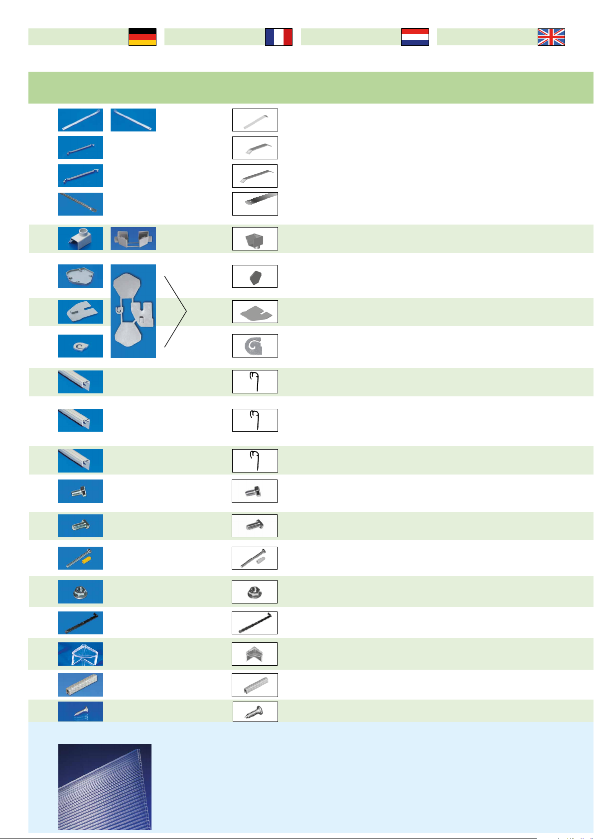
1. Überprüfen Sie bitte anhand der
Stückliste den Inhalt. Beachten
Sie die bereits vormontierten
Teile an den Profilen! Sehen Sie
die Vormontage als Aufbauhilfe und
achten Sie darauf, dass die vormon-
tierten Teile nicht aus den Profilen
herausrutschen. Scharfe Kanten
vorsorglich mit einer Feile brechen.
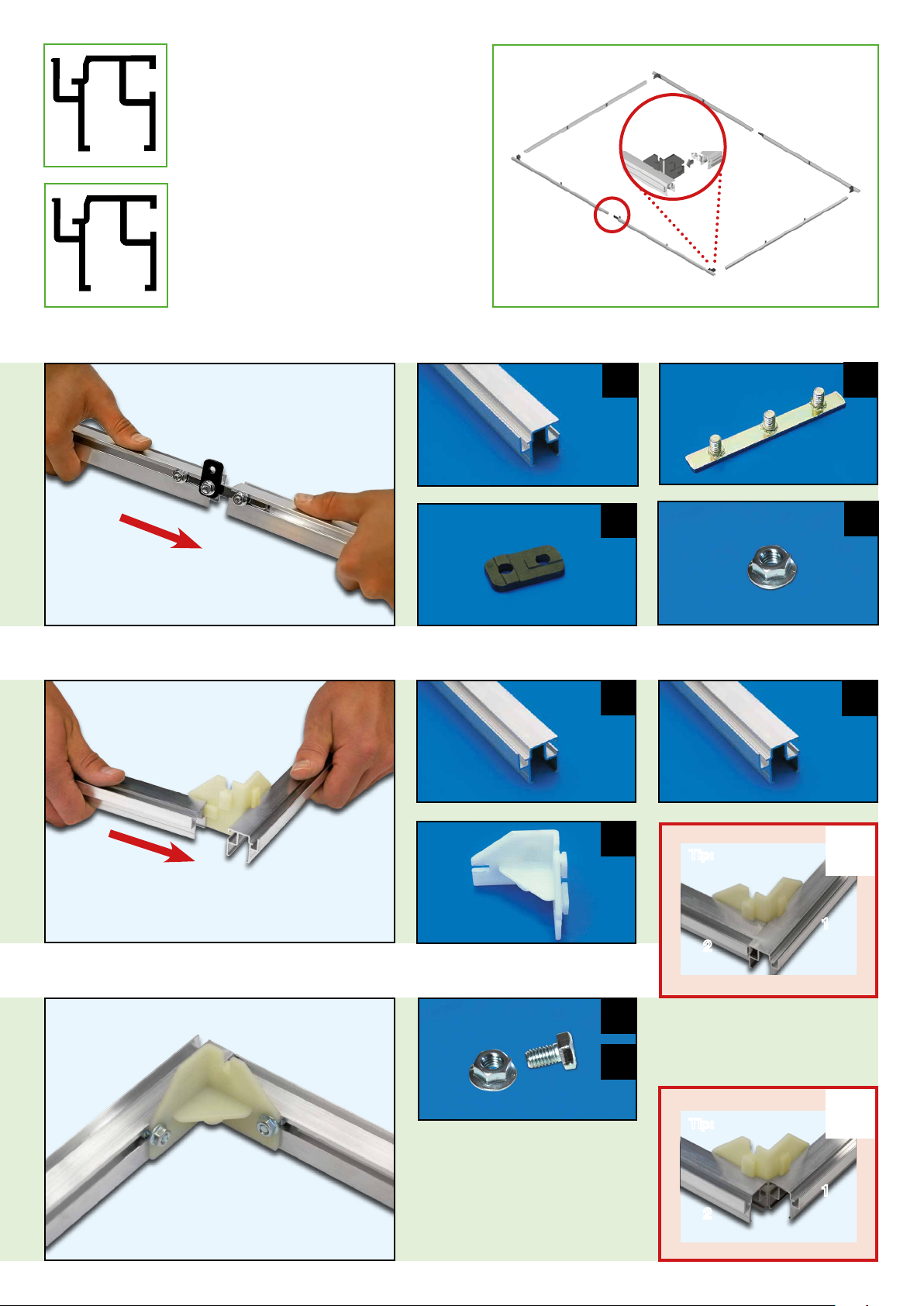
2. Wir empfehlen, Schrauben bei
der Montage zuerst nur handfest
anzuziehen (lose verschrauben),
um eventuell bei der Montage der
Stegplatten die Streben etwas ver-
schieben zu können. Das zusam-
mengebaute Gewächshaus mit der
Wasserwaage ausrichten und dann-
die Schrauben fest anziehen.
3. Wir empfehlen das Gewächshaus
auf ein betoniertes (frostsicheres)
bzw. gemauertes Fundament zu
stellen oder mit unserem Alumini-
um-Fundament (im Zubehör erhält-
lich) mit Winkel und Erdanker (im
Zubehör erhältlich) zu befestigen.
Achtung!
Bei der Montage empfehlen wir
Schutzhandschuhe. Der Aufbau
sollte auf ebenem Untergrund
erfolgen. Als Werkzeug brauchen
Sie einen Gabel- oder Sechskant-
schlüssel 10 mm. Effektiv ist auch
eine Ratsche mit 10er Nuss oder
ein Akkuschrauber (achten Sie
auf den richtigen Drehmoment!).
Beachten Sie die örtlichen Bau-
vorschriften.
Bei starkem Wind/Sturm ist das
Fenster und die Tür zu schließen.
Im Winter ist das komplette Dach
von Schneelast zu befreien.
Dear customer!
With this aluminum greenhouse you
have a greenhouse constructed with
the greatest care, whose aluminum
profile sections are especially ro-
bust due to a special manufacturing
process. As a result of the compact
construction method, rapid installa-
tion is possible. Versatile, possible
applications and a well-planned ac-
cessories program provide you with
opportunities for your own structu-
ring ideas!
We reserve the right to changes
and further developments as re-
quired by technical progress,
where slight deviations can arise
in case of the representations and
descriptions.
We wish you lots of fun and success
with your greenhouse.
Explanation about the assembly:
Before you begin with the assembly,
it is absolutely necessary that you
should first read through the direc-
tions completely and become fami-
liar with the individual module as-
semblies and profile sections. This
will be a significant help to you.
1. Please check the contents based
on the parts list. Note the already
pre-assembled parts on the
profile sections! Consider the
pre-assembly as a structure assis-
tance and note that the pre-assem-
bled parts do not slide from the pro-
file sections. Round off sharp edges
with a file as a precaution.
2. We recommend to tighten bolts
during the installation first by hand
only (screw together loosely) in order
to enable a possible displacement
of the struts during the installation of
the linking plates. Align the assem-
bled greenhouse with the spirit level
and then tightening the bolts fully.
3. We recommend to place the
greenhouse on a concreted (frost-
proof) or brickwork foundation or to
attach it using our aluminum found-
ation (available in accessories) with
angles and ground anchors (availab-
le in accessories).
Caution!
During the installation we recom-
mend to wear protective gloves.
The assembly should be imple-
mented on a flat underground
base. You need a 10 mm spanner
or a hexagon wrench as tool. Also
a 10 ratchet with nut or a battery
powered screwdriver is effective
(note the correct torque!).
Consider the local building regu-
lations.
In case of strong wind/storm, the
window and the door are to be
closed.In winter, the roof is to be
completely freed from snow load.
Chères clientes, chers clients !
Avec cette serre en aluminium, vous
avez fait l‘acquisition d‘une serre con-
struite avec le plus grand soin et dont
les profilés en aluminium sont parti-
culièrement stables grâce à un pro-
cédé spécial de fabrication.Grâce à
sa conception compacte, le montage
de la serre se fait très rapidement. De
nombreuses possibilités d‘utilisation
et un programme d‘accessoires intel-
ligents vous donnent libre cours pour
vos idées d‘agencement !
Nous nous réservons le droit
d‘apporter des modifications et
des améliorations en vue du pro-
grès technique. Ceci peut ent-
raîner quelques divergences au
niveau des représentations gra-
phiques et des descriptions.
Nous vous souhaitons beaucoup de
plaisir et de succès avec votre serre.
Explications relatives au montage :
Avant de commencer avec le mon-
tage de la serre, vous devez impé-
rativement lire intégralement la
notice de montage et vous famili-
ariser avec l‘ensemble des pièces
détachées et les profilés. Cela
vous sera d‘une aide précieuse.
1. Veuillez contrôler le contenu à l‘aide
de la liste des pièces. Attention aux
pièces déjà préassemb lées sur
les profilés. Veuillez considérer le
préassemblage comme une aide au
montage et veillez à ce que les pi-
èces préassemblées ne se dégagent
pas des profilés. Par précaution,
veuillez limer les bords tranchants.
2. Dans un premier temps, nous
vous recommandons de serrer les
vis uniquement à la main lors de
l‘assemblage (vissage sans serrer)
afin de pouvoir déplacer éventuelle-
ment les entretoises lors du montage
des plaques à nervures. Aligner la
serre ainsi assemblée à l’aide d’un
niveau à bulle, puis serrer fermement
les vis.
3. Nous vous recommandons de
poser la serre sur une fondation bé-
tonnée ou maçonnée (ingélif) ou de
la fixer par nos profilés de fondation
en aluminium (disponibles en tant
qu’accessoire) à l’aide d‘angles et de
tirant d’ancrage.
Attention !
Lors du montage, nous vous re-
commandons de porter des gants
de protection. Le montage doit être
réalisé sur un sous-sol plat. Les ou-
tils dont vous avez besoin sont une
clé plate ou une clé à six pans de
10 mm. Un cliquet adaptable avec
un embout de 10 mm ou un tour-
nevis électrique (respecter le bon
couple de serrage !) sont aussi ef-
ficaces. Respecter, le cas échéant,
les prescriptions en matières de
construction. Fermer les portes
et les fenêtres en cas de vent fort
ou de tempête. En hiver, enlever la
couche de neige sur le toit.
Geachte klant!
Met de aluminium broeikas bezit u
een met de grootste zorgvuldigheid
geconstrueerde broeikas, waarvan
de aluminiumprofielen door een spe-
ciaal productieproces uiterst stabiel
zijn.Door de compacte constructie-
wijze is een snelle montage mogelijk.
Veelzijdige toepassingsmogelijkhe-
den en een doordacht assortiment
aan toebehoren geven u ruimte voor
eigen inrichtingsideeën!
Wij behouden ons het recht voor,
wijzigingen en verdere ontwikke-
lingen op basis van de technische
vooruitgang door te voeren, waar-
door minimale afwijkingen in de
afbeeldingen en beschrijvingen
kunnen ontstaan.
Wij wensen u veel plezier en succes
met uw broeikas.
Toelichting bij de opbouw:
Voordat u met de opbouw begint,
dient u beslist eerst de comple-
te handleiding door te nemen en
u met de individuele modules en
profielen vertrouwd te maken.
Het zal voor u een essentieel hul-
pmiddel zijn.
1. Gelieve aan de hand van de
stuklijst de inhoud te controleren.
Denk aan reeds vooraf ge-
monteerde onderdelen aan
de profielen! Beschouw de voo-
rafgaande montage als opbouwhul-
pmiddel en let erop dat de vooraf
gemonteerde onderdelen niet uit de
profielen glijden. Scherpe kanten uit
voorzorg met een vijl breken. 2. Wij
raden aan, schroeven bij de monta-
ge eerst slechts losjes met de hand
aan te draaien (los vastschroeven)
om eventueel bij de montage van
de lijfplaten de schoren een beetje
te kunnen verschuiven. De gemon-
teerde broeikas met het waterpas
uitlijnen en dan de schroeven vast
aandraaien. 3. Wij raden aan, de
broeikas op een gebetonneerd
(vorstbestendig) c.q. gemetseld
fundament te zetten of met ons (bij
de toebehoren verkrijgbare) alumi-
niumfundament met winkelhaak en
grondanker (bij de toebehoren ver-
krijgbaar) te bevestigen.
Opgelet!
Bij de montage raden wij bescher-
mende handschoenen aan. De op-
bouw dientop eeneffenondergrond
te gebeuren. Als gereedschap hebt
u een steek- of inbussleutel 10 mm
nodig. Efficiënt is ook een ratelin-
richting met verwisselbare kop nr.
10 of een accuschroevendraaier
(let op het correcte draaimoment!).
Neem de lokale bouwvoorschrif-
ten in acht.
Bij sterke wind/storm dienen het
venster en de deur gesloten te
worden. In de winter dient het ge-
hele dak sneeuwvrij te worden.

4
Deutsch
English
FrançaisNetherlands
Bodenprofil Seitenwand Profilé à fixer au sol de la paroi latérale •
Bodemprofiel zijwand • Side wall floor profile section
Bodenprofil Front- u. Rückwand Profilé à fixer au sol de la paroi avant et arrière •
Bodemprofiel voor- en achterwand • Front and back wall floor profile section
Eckprofil Profilé d‘angle • Hoekprofiel • Corner profile section
Giebelprofil Dach Profilé du fronton du toit • Gevelprofiel dak •
Roof gable profile section
a) Querstrebe b) Türquerstrebe a) Entretoise transversale
b) Entretoise transversale de la porte • a) Dwarsbalk b) Deurdwarsbalk • a) Crossbeam b) Door crossbeam
Strebe Front- u. Rückwand Entretoise de la paroi avant et arrière •
Schoor voor- en achterwand • Front and back wall strut
Türscharnierstrebe Entretoise pour les charnières de porte •Deurscharnierschoor •
Door hinge strut
Regenrinne Gouttière • Regengoot • Rainwater gutter
Firstprofil Profilé du faîtage • Nokprofiel • Roof ridge profile section
Seitenstrebe Entretoise latérale • Zijschoor • Side strut
Dachstrebe Entretoise du toit • Dakschoor • Roof strut
Fensterquerstrebe Entretoise transversale de la fenêtre • Vensterdwarsbalk •
Window crossbeam
Fenster Fenêtre • Venster • Window
a) Türteile b) Türdrückergarnitur a) Partie de la porte
b) Garniture de poignée de porte • a) Deuronderdelen b) Deurklinkgarnituur • a) Door parts b) Door handle fitting
Bodeneckverbinder raccord angulaire à fixer au sol • Bodemhoekverbindingsstuk •
Floor corner connector
Giebel- und Firstverbinder Raccord du fronton et raccord du faîtage •
Gevel- en nokverbindingsstuk • Gable and roof ridge connector
Strebenverbinder Raccord d’entretoise • Schoorverbindingsstuk • Strut connector
Strebenhalter gerade schwarz (ohne Nase) Support d‘entretoise droit noir
(sans bord d‘attaque) • Schoorhouder recht zwart (zonder neus) • Strut bracket straight, black (without nose)
Strebenhalter gerade weiß (mit Nase) Support d‘entretoise droit blanc (avec bord d‘attaque)
• Schoorhouder recht wit (met neus) • Strut bracket straight, white (with nose)
Strebenverbinder gebogen schwarz (ohne Nase)
Raccord d’entretoise bombé (sans bord
d‘attaque) • Schoorverbindingsstuk gebogen zwart (zonder neus) • Strut connector curved, black (without nose)
Stebenverbinder gebogen weiß (mit Nase)
Raccord d’entretoise bombé (sans bord
d‘attaque) • Schoorverbindingsstuk gebogen wit (met neus) • Strut connector curved, white (with nose)
Stückliste* Liste de pièces Stuklijst Bill of Material
English
NetherlandsFrançaisDeutsch
*Beachten Sie die vormontierten Teile
an den Profilen!
Art.-Nr.: Bezeichnung Désignation • Omschrijving • Designation
1 1540 2 2280 2 1500 4 1500 2 2240 4
2240 2
2 2220 2 2220 2 2220 2 2220 2 2220 2
3 1260 4 1260 4 1260 4 1260 4 1260 4
4 1260 4 1260 4 1260 4 1260 4 1260 4
5 a b 750 2 750 2 750 2 750 2 750 2
6 1680 3 1680 3 1680 3 1680 3 1680 3
7 1680 1 1680 1 1680 1 1680 1 1680 1
8 1540 2 2280 2 1500 4 1500 2 2240 4
2240 2
9 1540 1 2280 1 1500 2 1500 1 2240 2
2240 1
10 1260 2 1260 4 1260 6 1260 8 1260 10
11 1260 2 1260 4 1260 6 1260 8 1260 10
12 715 1 715 1 715 1 715 2 715 2
13 1 1 1 2 2
14 a b 2 2 2 2 2
15 4 4 4 4 4
16 6 6 6 6 6
17 - - 5 5 5
18 a 2 2 4 6 6
18 b 6 8 8 10 12
19 a 2 2 5 5 5
19 b 3 6 6 9 12
9291459 = 1500 mm
9291458 = 1540 mm
9291456 = 2240 mm
9291455 = 2280 mm
9291457 = 2220 mm
9291471
9291483
a) 9291489
b) 9291492
9291537
9291504
9291513 = 1500 mm
9291512 = 1540 mm
9291510 = 2240 mm
9291509 = 2280 mm
9291522 = 1500 mm
9291521 = 1540 mm
9291519 = 2240 mm
9291518 = 2280 mm
9291540
9291540
9291552
9291555
a) 9291558
b) 9291785
9291688
9291691
9291694
9291703
9291700
9291709
9291706

5
200 cm
227 cm 154 cm
130 cm
F2
200 cm
227 cm 228 cm
130 cm
F3
200 cm
227 cm
300 cm
130
F4
200 cm
227 cm
374 cm
130 cm
F5
200 cm
227 cm
448 cm
130 cm
F6
Bodenprofil Seitenwand Profilé à fixer au sol de la paroi latérale •
Bodemprofiel zijwand • Side wall floor profile section
Bodenprofil Front- u. Rückwand Profilé à fixer au sol de la paroi avant et arrière •
Bodemprofiel voor- en achterwand • Front and back wall floor profile section
Eckprofil Profilé d‘angle • Hoekprofiel • Corner profile section
Giebelprofil Dach Profilé du fronton du toit • Gevelprofiel dak •
Roof gable profile section
a) Querstrebe b) Türquerstrebe a) Entretoise transversale
b) Entretoise transversale de la porte • a) Dwarsbalk b) Deurdwarsbalk • a) Crossbeam b) Door crossbeam
Strebe Front- u. Rückwand Entretoise de la paroi avant et arrière •
Schoor voor- en achterwand • Front and back wall strut
Türscharnierstrebe Entretoise pour les charnières de porte •Deurscharnierschoor •
Door hinge strut
Regenrinne Gouttière • Regengoot • Rainwater gutter
Firstprofil Profilé du faîtage • Nokprofiel • Roof ridge profile section
Seitenstrebe Entretoise latérale • Zijschoor • Side strut
Dachstrebe Entretoise du toit • Dakschoor • Roof strut
Fensterquerstrebe Entretoise transversale de la fenêtre • Vensterdwarsbalk •
Window crossbeam
Fenster Fenêtre • Venster • Window
a) Türteile b) Türdrückergarnitur a) Partie de la porte
b) Garniture de poignée de porte • a) Deuronderdelen b) Deurklinkgarnituur • a) Door parts b) Door handle fitting
Bodeneckverbinder raccord angulaire à fixer au sol • Bodemhoekverbindingsstuk •
Floor corner connector
Giebel- und Firstverbinder Raccord du fronton et raccord du faîtage •
Gevel- en nokverbindingsstuk • Gable and roof ridge connector
Strebenverbinder Raccord d’entretoise • Schoorverbindingsstuk • Strut connector
Strebenhalter gerade schwarz (ohne Nase) Support d‘entretoise droit noir
(sans bord d‘attaque) • Schoorhouder recht zwart (zonder neus) • Strut bracket straight, black (without nose)
Strebenhalter gerade weiß (mit Nase) Support d‘entretoise droit blanc (avec bord d‘attaque)
• Schoorhouder recht wit (met neus) • Strut bracket straight, white (with nose)
Strebenverbinder gebogen schwarz (ohne Nase)
Raccord d’entretoise bombé (sans bord
d‘attaque) • Schoorverbindingsstuk gebogen zwart (zonder neus) • Strut connector curved, black (without nose)
Stebenverbinder gebogen weiß (mit Nase)
Raccord d’entretoise bombé (sans bord
d‘attaque) • Schoorverbindingsstuk gebogen wit (met neus) • Strut connector curved, white (with nose)
Länge Stück
Longueur Pièce
Lengte stuk(s)
Length Piece
Länge Stück
Longueur Pièce
Lengte stuk(s)
Length Piece
Länge Stück
Longueur Pièce
Lengte stuk(s)
Length Piece
Länge Stück
Longueur Pièce
Lengte stuk(s)
Length Piece
Länge Stück
Longueur Pièce
Lengte stuk(s)
Length Piece
Art.-Nr.: Bezeichnung Désignation • Omschrijving • Designation
1 1540 2 2280 2 1500 4 1500 2 2240 4
2240 2
2 2220 2 2220 2 2220 2 2220 2 2220 2
3 1260 4 1260 4 1260 4 1260 4 1260 4
4 1260 4 1260 4 1260 4 1260 4 1260 4
5 a b 750 2 750 2 750 2 750 2 750 2
6 1680 3 1680 3 1680 3 1680 3 1680 3
7 1680 1 1680 1 1680 1 1680 1 1680 1
8 1540 2 2280 2 1500 4 1500 2 2240 4
2240 2
9 1540 1 2280 1 1500 2 1500 1 2240 2
2240 1
10 1260 2 1260 4 1260 6 1260 8 1260 10
11 1260 2 1260 4 1260 6 1260 8 1260 10
12 715 1 715 1 715 1 715 2 715 2
13 1 1 1 2 2
14 a b 2 2 2 2 2
15 4 4 4 4 4
16 6 6 6 6 6
17 - - 5 5 5
18 a 2 2 4 6 6
18 b 6 8 8 10 12
19 a 2 2 5 5 5
19 b 3 6 6 9 12

6
Deutsch
English
FrançaisNetherlands
Stückliste* Liste de pièces Stuklijst Bill of Material
Stegplatten
6 mm
Onderlegplaatje deurmidden grijs • Door middle underlay plate, gray
Fensteröffner manuell schwarz Ouvre-fenêtre manuel noir •
Vensteropener handmatig zwart • Window opener manual, black
Schutzklappe klar Cache clair • Beschermkapje transparant •
Protective cap, transparent
Schutzprofil Gummi Profilé de protection en caoutchouc • Beschermprofiel
rubber • Rubber protective profile section
Rückseite mitte Côté arrière central • Achterzijde midden • Rear side middle
Rück- & Frontseite seitlich Côté arrière et avant latéral • Achter- & voorzijde zijdelings • Side rear & front side laterally
Front Spitz Avant pointu • Voorzijde uiteinde • Front tip
Türteile vormontiert
Parties de la porte préassemblées • Deuronderdelen vooraf gemonteerd • Door parts pre-assembled
Seite und Dach Côté et toit • Zijkant en dak • Side and roof
Fenster vormontiert
Fenêtre préassemblée • Venster vooraf gemonteerd • Window pre-assembled
Fensterdachfeld Partie de la fenêtre du toit • Vensterdakveld • Window roof area
English
NetherlandsFrançais
Deutsch
Art.-Nr.: Bezeichnung Désignation • Omschrijving • Designation
20 a 355 2
+
2 355 2
+
2 355 - 355 - 355 -
20 b 260 - 260 - 260 2 260 4 260 6
20 c 465 - 465 - 465 1 465 2 465 3
20 d 815 - 815 - 815 8 815 8 815 8
21 4 4 4 4 4
22 2 2 2 2 2
23 1 1 1 1 1
24 1 1 1 1 1
25 710 4 710 6 710 8 710 10 710 12
26 1260 4 1260 4 1260 4 1260 4 1260 4
27 1480 2 2220 2 2220 2 2220 2 2220 4
710 2 710 4
28 M6x10 62 M6x10 70 M6x10 74 M6x10 84 M6x10 92
29 RHx10 12 RHx10 12 RHx10 26 RHx10 34 RHx10 40
30 M6x70 2 M6x70 2 M6x70 2 M6x70 4 M6x70 4
31 M6 76 M6 84 M6 117 M6 137 M6 151
- - 15* 15* 15*
32 420 1 420 1 420 1 420 2 420 2
33 4 4 4 4 4
34 45 4 45 4 45 4 45 4 45 4
35 Schraube für Clipprofil
Vis de Profilé à clipser • Clipprofielschroef • clip profile bolt
4,2 x 16 12 4,2 x 16 12 4,2 x 16 12 4,2 x 16 12 4,2 x 16 12
A1915x730 1 1915x730 1 1915x730 1 1915x730 1 1915x730 1
BL 1705x730 2 1705x730 2 1705x730 2 1705x730 2 1705x730 2
BR 1705x730 2 1705x730 2 1705x730 2 1705x730 2 1705x730 2
C225x730 1 225x730 1 225x730 1 225x730 1 225x730 1
D835x730 2 835x730 2 835x730 2 835x730 2 835x730 2
E1275x730 7 1275x730 11 1275x730 15 1275x730 18 1275x730 22
F 650x730 1 650x730 1 650x730 1 650x730 2 650x730 2
G625x730 1 625x730 1 625x730 1 625x730 2 625x730 2
9291295
9291289
9291292
9291298
9291277
9291280
9291283
9291286
*Beachten Sie die vormontierten Teile
an den Profilen!
a) Windverband
(2 x rechts + 2 x links)
a) Contreventement (2 x droit + 2 x gauche) •
a) Windverband (2 x rechts + 2 x links) • a) Transverse brace (2 x right + 2 x left)
b) Seitenverbinder b) Raccord latéral • b) Zijverbindingsstuk • b) Side connector
c) Dachstrebenverbinder c) Raccord d‘entretoise du toit •
c) Dakschoorverbindingsstuk • c) Roof strut connector
d) Zusatzverbinder d) Raccord supplémentaire • d) Extra verbindingsstuk •
d) Additional connector
Regenablauf grau (rechts + links = 1 Paar)
Écoulement des eaux de pluie gris (droit +
gauche = 1 paire) • Regenwaterput grijs (rechts + links = 1 paar) • Rain run-off, gray (right + left = 1 pair)
Firstabdeckung grau
Cache du faîtage gris • Nokafdekking grijs • Ridge cover, gray
Türhalter-unten grau
Support de porte inférieur gris • Deurhouder-onderaan grijs •
Door holder below, gra
y
Unterlegscheibe Türmitte grau Blocage de porte central gris •
Clipprofil Dach unten (Regenrinne) Profilé à clipser inférieur de toit (gouttière) •
Clipprofiel dak onderaan (regengoot ) • Roof clip profile section below (rainwater gutter)
Clipprofil Giebel
Profilé à clipser du fronton • Clipprofiel gevel • Gable clip profile section
Clipprofil Seite (Regenrinne) Profilé à clipser latéral (gouttière) •
Clipprofiel zijkant (regengoot ) • Side clip profile section (rainwater gutter)
M6-Schraube Vis M6 • M6-schroef • M6 bolt
Rhombusschraube Vis losange • Ruitschroef • Rhombus bolt
Dachfensterschraube mit Schutzkappe Vis de fenêtre du toit avec cache •
Dakvensterschroef met beschermkapje • Rooflight bolts with protective cap
Mutter mit Flansch (*je 3 pro Strebenverbinder) Écrou avec bride (*chacun 3 par-
raccord d‘entretoise) • Moer met flens (*telkens 3 per schoorverbindingsstuk• Nut with flange
a) 9291697 links
b) 9291698 rechts
9291715
9291712
9291809
9291721
9291718
9291724
9291727
9291728
9291730
9291733
9291739
9291742
Schraube
9291745
Kappe
9291736
9291788
9291791
9291748
9291735

7
200 cm
227 cm 154 cm
130 cm
F2
200 cm
227 cm 228 cm
130 cm
F3
200 cm
227 cm
300 cm
130
F4
200 cm
227 cm
374 cm
130 cm
F5
200 cm
227 cm
448 cm
130 cm
F6
Länge Stück
Longueur Pièce
Lengte stuk(s)
Length Piece
Länge Stück
Longueur Pièce
Lengte stuk(s)
Length Piece
Länge Stück
Longueur Pièce
Lengte stuk(s)
Length Piece
Länge Stück
Longueur Pièce
Lengte stuk(s)
Length Piece
Länge Stück
Longueur Pièce
Lengte stuk(s)
Length Piece
Art.-Nr.: Bezeichnung Désignation • Omschrijving • Designation
20 a 355 2
+
2 355 2
+
2 355 - 355 - 355 -
20 b 260 - 260 - 260 2 260 4 260 6
20 c 465 - 465 - 465 1 465 2 465 3
20 d 815 - 815 - 815 8 815 8 815 8
21 4 4 4 4 4
22 2 2 2 2 2
23 1 1 1 1 1
24 1 1 1 1 1
25 710 4 710 6 710 8 710 10 710 12
26 1260 4 1260 4 1260 4 1260 4 1260 4
27 1480 2 2220 2 2220 2 2220 2 2220 4
710 2 710 4
28 M6x10 62 M6x10 70 M6x10 74 M6x10 84 M6x10 92
29 RHx10 12 RHx10 12 RHx10 26 RHx10 34 RHx10 40
30 M6x70 2 M6x70 2 M6x70 2 M6x70 4 M6x70 4
31 M6 76 M6 84 M6 117 M6 137 M6 151
- - 15* 15* 15*
32 420 1 420 1 420 1 420 2 420 2
33 4 4 4 4 4
34 45 4 45 4 45 4 45 4 45 4
35 Schraube für Clipprofil
Vis de Profilé à clipser • Clipprofielschroef • clip profile bolt
4,2 x 16 12 4,2 x 16 12 4,2 x 16 12 4,2 x 16 12 4,2 x 16 12
A1915x730 1 1915x730 1 1915x730 1 1915x730 1 1915x730 1
BL 1705x730 2 1705x730 2 1705x730 2 1705x730 2 1705x730 2
BR 1705x730 2 1705x730 2 1705x730 2 1705x730 2 1705x730 2
C225x730 1 225x730 1 225x730 1 225x730 1 225x730 1
D835x730 2 835x730 2 835x730 2 835x730 2 835x730 2
E1275x730 7 1275x730 11 1275x730 15 1275x730 18 1275x730 22
F 650x730 1 650x730 1 650x730 1 650x730 2 650x730 2
G625x730 1 625x730 1 625x730 1 625x730 2 625x730 2
a) Windverband
(2 x rechts + 2 x links)
a) Contreventement (2 x droit + 2 x gauche) •
a) Windverband (2 x rechts + 2 x links) • a) Transverse brace (2 x right + 2 x left)
b) Seitenverbinder b) Raccord latéral • b) Zijverbindingsstuk • b) Side connector
c) Dachstrebenverbinder c) Raccord d‘entretoise du toit •
c) Dakschoorverbindingsstuk • c) Roof strut connector
d) Zusatzverbinder d) Raccord supplémentaire • d) Extra verbindingsstuk •
d) Additional connector
Regenablauf grau (rechts + links = 1 Paar)
Écoulement des eaux de pluie gris (droit +
gauche = 1 paire) • Regenwaterput grijs (rechts + links = 1 paar) • Rain run-off, gray (right + left = 1 pair)
Firstabdeckung grau
Cache du faîtage gris • Nokafdekking grijs • Ridge cover, gray
Türhalter-unten grau
Support de porte inférieur gris • Deurhouder-onderaan grijs •
Door holder below, gra
y
Unterlegscheibe Türmitte grau Blocage de porte central gris •
Clipprofil Dach unten (Regenrinne) Profilé à clipser inférieur de toit (gouttière) •
Clipprofiel dak onderaan (regengoot ) • Roof clip profile section below (rainwater gutter)
Clipprofil Giebel
Profilé à clipser du fronton • Clipprofiel gevel • Gable clip profile section
Clipprofil Seite (Regenrinne) Profilé à clipser latéral (gouttière) •
Clipprofiel zijkant (regengoot ) • Side clip profile section (rainwater gutter)
M6-Schraube Vis M6 • M6-schroef • M6 bolt
Rhombusschraube Vis losange • Ruitschroef • Rhombus bolt
Dachfensterschraube mit Schutzkappe Vis de fenêtre du toit avec cache •
Dakvensterschroef met beschermkapje • Rooflight bolts with protective cap
Mutter mit Flansch (*je 3 pro Strebenverbinder) Écrou avec bride (*chacun 3 par-
raccord d‘entretoise) • Moer met flens (*telkens 3 per schoorverbindingsstuk• Nut with flange

8
Deutsch
English
FrançaisNetherlands
Montage
der Bodenprofile
Einige Montageteile sind bereits
an den Profilen vormontiert.
Die Form der Bodenprofile ist
identisch, beachten Sie die Län-
ge um die Profile zu definieren.
Beachten Sie, dass das Bo-
denprofil Seitenwand, das Bo-
denprofil Front- und Rückwand
überlappen muss!
Installation of the floor
profile sections
Some components are already
pre-assembled on the profile
sections.
The form of the floor profile sec-
tions is identical, note that you
define the length around the
profile sections.
Note that the side wall floor
profile section must overlap the
front and rear wall floor profile
section!
Montage des profilés à
fixer au sol
Quelques pièces de montage
sont déjà préassemblées sur les
profilés.
La forme des profilés à fixer au
sol est identique, identifier la
longueur afin de distinguer les
profilés. Faire attention à ce que
le profilé à fixer au sol de la paroi
latérale se chevauche bien avec
le profilé à fixer au sol de la paroi
avant et arrière !
Montage van de
bodemprofielen
Enkele montageonderdelen zijn
reeds vooraf aan de profielen
gemonteerd.
De vorm van de bodemprofielen
is identiek, let op de lengte om
de profielen te definiëren.
Neem in acht dat het bodem-
profiel zijwand het bodemprofiel
voor- en achterwand moet over-
lappen!
A 1.
Bodenseitenprofile
verbinden
(nur F4 bis F6)
Die zweiteiligen Bodenprofile Sei-
tenwand (1) mittels Strebenverbin-
der (17) zusammenstecken und
mit Muttern (31) fest verschrau-
ben. Seitenteilstrebenhalter (18a)
in der Mitte anbringen.
A 1.
connect floor side profile
sections
(only F4 to F6)
Interconnect the two-part floor
profiles side wall (1) by means of
strut connector (17) and screw
tightly together with nuts (31).
Attach side part strut bracket
(18a) in the middle.
A 1.
Profilés à fixer au sol
latéraux à relier
(uniquement F4 jusqu‘à F6)
Assembler (1) les profilés à fixer
au sol et divisés en deux parties à
l’aide des raccords d’entretoise
(17) et d‘écrous (31). Poser le
support d‘entretoise de la partie
latérale (18a) au centre.
A 1.
Bodemzijprofielen
verbinden
(enkel F4 tot F6)
De tweedelige bodemprofie-
len zijwand (1) door middel
van schoorverbindingsstuk (17)
aaneenspelden en met moe-
ren (31) vast dichtschroeven.
Zijstukschoorhouder (18a) in het
midden aanbrengen.
A 2.
Bodenprofile
aufstecken
Bodeneckverbinder (15) auf Bo-
denprofil Seitenwand (1) auf-
stecken. Dann das Bodenprofil
Front- und Rückwand (2) auf
den Eckverbinder aufschieben
bis es am Bodenprofil-Seiten-
wand (1) ansteht.
Tip: Richtig! Das Seitenprofil über-
lappt das Frontprofil!
A 2.
insert floor profile
sections insert
Insert floor corner connectors
(15) onto side wall floor profile
section (1). Then slide the front
and rear wall floor profile sec-
tion (2) onto the corner connec-
tor until it is at the floor profile
section side wall (1).
Tip: Correct! The side profile section
overlaps the front profile section!
A 2.
Monter les profilés
à fixer au sol
Monter le raccord angulaire à fixer
au sol(15) surle raccordd’entretoise
de la paroi latérale (1). Ensuite, in-
sérer le raccord d‘entretoise de
la paroi avant et arrière (2) sur le
raccord angulaire jusqu‘à ce qu‘il
soit placé sur le profilé à fixer au
sol de la paroi latérale (1).
Conseil :
Correct ! Le profilé latéral
doit chevaucher le profilé avant !
A 2.
Bodemprofielen
opsteken
Bodemhoekverbindingsstuk
(15) op bodemprofiel zijwand (1)
steken. Dan het bodemprofiel
voor- en achterwand (2) op het
hoekverbindingsstuk schuiven
tot het tegen de bodempro-
fielzijwand (1) staat.
Tip: Correct! Het zijprofiel over-
lapt het voorprofiel!
A 3.
Bodenprofile 1 und 2 ver-
schrauben
Mittels Schrauben (28) und Mut
tern (31) den Bodeneckverbinder
(15) in allen vier Ecken mit den
Profilen (1 und 2) verschrauben.
Tip: Falsch! Das Seitenprofil
überlappt nicht.
A 3.
Screw together floor profi-
le sections 1 and 2
Screw the floor corner connec-
tor (15) with the profile sections
(1 and 2) by means of bolts (28)
and nuts (31) in all four corners.
Tip: Incorrect! The side profile
section does not overlap.
A 3.
Visser les profilés à fixer
au sol 1 et 2
Visser le raccord angulaire à fi-
xer au sol (15) aux quatre coins
avec les profilés (1 et 2 ) à l‘aide
de vis (28) et d‘écrous (31).
Conseil : Incorrect ! Le profilé
latéral ne se chevauche pas.
A 3.
Bodemprofielen 1 en 2
vastschroeven
Door middel van schroeven (28)
en moeren (31) het bodemhoek-
verbindingsstuk (15) in alle vier
hoeken met de profielen (1 en 2)
vastschroeven.
Tip: Fout! Het zijprofiel over-
lapt niet.

9
A
A 1 A 2
1
18a
17
12
15
A1
A2
1.
Bodenprofil Seitenwand
Side wall floor profile section
Profilé à fixer au sol de la paroi latérale
Bodemprofiel zijwand
2.
Bodenprofil Front und Rückwand
Floor profile section of front and back wall
Profilé à fixer au sol de la paroi avant et arrière
Bodemprofiel voor- en achterwand
1
2
12
1
1
2
2
1
1
2
2
Bild: rechts vorne / links hinten
Illustration: right in front / left behind
Figure : avant droite / arrière gauche
Afbeelding: rechts vooraan / links achteraan
Bild: rechts vorne / links hinten
Illustration: right in front / left behind
Figure : avant droite / arrière gauche
Afbeelding: rechts vooraan / links achteraan
links vorne
left in front
avant gauche
Links vooraan
28
31
Tip:
Tip: 4
7
31

10
Deutsch
English
FrançaisNetherlands
Montage der Eck-
und Giebelprofile
Eckprofil (3) und Giebelprofil (4)
sind sich sehr ähnlich, achten
Sie auf die roten Kreise auf den
Produktfotos.
Einige Montageteile sind bereits
an den Profilen vormontiert.
Installation of the corner
and gable profile sections
Corner profile section (3) and
gable profile section (4) are very
similar, note the red rings on the
product photographs.
Some components are already
pre-assembled on the profile
sections.
Montage des profilés
d‘angle et des profilés
du fronton
Le profilé d‘angle (3) et le profi-
lé du fronton (4) se ressemblent
fortement, faire attention aux
cercles rouges sur les images
du produit.
Quelques pièces de montage
sont déjà préassemblées sur les
profilés.
Montage van de hoek-
en gevelprofielen
Hoekprofiel (3) en gevelpro-
fiel (4) gelijken sterk op elkaar,
let op de rode cirkels op de
productfoto’s.
Enkele montageonderdelen zijn
reeds vooraf aan de profielen
gemonteerd.
B 1.
Montage
Eckprofile
Die Eckprofile (3) werden auf
den bereits montierten Boden-
eckverbinder (15) aufgesteckt
und mit Schrauben (28) und
Muttern (31) verschraubt.
Tip:
Lassen Sie die Schrauben
von oben in das Profil fallen.
B 1.
Installation
of corner profile section
The corner profile sections (3)
are inserted onto the already as-
sembled floor corner connector
(15) and screwed with bolts (28)
and nuts (31).
Tip: Allow the bolts to fall from
above into the profile section.
B 1.
Montage
des profilés d‘angle
Les profilés d‘angle (3) sont
montés sur les raccords angu-
laires à fixer au sol (15) déjà as-
semblés et vissés avec des vis
(28) et des écrous (31).
Conseil : Laisser les vis tomber
du haut dans le profilé.
B 1.
Montage
hoekprofielen
De hoekprofielen (3) worden op
het reeds gemonteerde bodem-
hoekverbindingsstuk (15) gezet
en met schroeven (28) en moe-
ren (31) vastgeschroefd.
Tip:
Laat de schroeven van bo-
ven in het profiel vallen.
B 2.
Giebelprofile im First
verbinden
Giebelprofile (4) bis zum Ansch-
lag auf den Firstverbinder (16)
stecken und verschrauben.
Die Lasche mit der Einkerbung für
das Firstprofil zeigt nach innen.
B 2.
Connect gable profile sec-
tions in the roof ridge
Insert gable profile sections (4)
up to the stop collar on the roof
ridge connector (16) and screw
together.
The strap with the notch for the
roof ridge profile section is turned
to inside.
B 2.
Raccorder les profilés
d‘angle et du fronton
Monter les profilés du fronton (4)
jusqu‘en butée sur le faîtage (16)
et les visser.
La languette avec la rainu-
re du faîtage est dirigée vers
l‘intérieur.
B 2.
Gevelprofielen in de nok
verbinden
Gevelprofielen (4) tot aan de
aanslag op het nokverbindings-
stuk (16) zetten en vastschroe-
ven.
De lasplaat met de inkeping voor
het nokprofiel wijst naar binnen.
B 3.
Eck- und Giebelprofile
verbinden
Giebelverbinder (16) auf die Gie-
belprofile (4) stecken und ver-
schrauben. Danach die Giebel-
verbinder (16) auf das Eckprofil
(3) aufschieben und mit Schrau-
ben (28) und Muttern (31) ver-
schrauben. Die Lasche mit der
Einkerbung für das Firstprofil
zeigt nach innen.
Tip:
Achten Sie auf die richtige
Lasche beim aufstecken.
B 3.
Connect corner and gable
profile sections
Insert gable connectors (16) onto
the gable profile sections (4) and
screw together. After that, insert
the gable connectors (16) onto
the corner profile section (3) and
screw together with bolts (28)
and nuts (31). The strap with the
notch for the roof ridge profile
section is turned to inside.
Tip:
Note the correct strap with
insertion.
B 3.
Raccorder les profilés
d‘angle et du fronton
Monter les raccords du fronton
(16) sur les profilés du fronton
(4) et les visser. Ensuite, monter
les raccords du fronton (16) sur
le profilé d‘angle (3) et les visser
avec des vis (28) et des écrous
(31). La languette avec la rai-
nure du faîtage est dirigée vers
l‘intérieur.
Conseil :
Veiller à utiliser la bon-
ne languette lors du montage.
B 3.
Hoek- en gevelprofielen
verbinden
Gevelverbindingsstuk (16) op
de gevelprofielen (4) zetten en
vastschroeven. Daarna de ge-
velverbindingsstukken (16) op
het hoekprofiel (3) schuiven en
met schroeven (28) en moeren
(31) vastschroeven. De lasplaat
met de inkeping voor het nok-
profiel wijst naar binnen.
Tip:
Let op de correcte lasplaat
bij het opsteken.

11
B
3
4
28
31
16
16
A 2
B1
3.
Eckprofil
Corner profile section
Profilé d‘angle
Hoekprofiel
4.
Giebelprofil
Gable profile section
Profilé du fronton
Gevelprofiel
B3
B2
28
31
28
31
Tip:
Tip:

12
Deutsch
English
FrançaisNetherlands
Montage der
Rückwand
Entscheiden Sie nun auf wel-
cher Seite der Eingang des Ge-
wächshauses sein soll.
Danach beginnen Sie mit der
Rückwandmontage.
Einige Montageteile sind bereits
an den Profilen vormontiert.
Installation of
back wall
Decide now on which side the
entrance of the greenhouse
should be.
After that, begin with the back
wall installation.
Some components are already
pre-assembled on the profile
sections.
Montage de
la paroi arrière
Déterminer tout d‘abord de quel
côté l‘entrée de la serre en alu-
minium sera dirigée.
Commencez ensuite avec le
montage de la paroi arrière.
Quelques pièces de montage
sont déjà préassemblées sur les
profilés.
Montage van de
achterwand
Beslis nu aan welke zijde de in-
gang van de broeikas dient te
zijn.
Daarna begint u met de monta-
ge van de achterwand.
Enkele montageonderdelen zijn
reeds vooraf aan de profielen
gemonteerd.
C 2.
Rückwandstrebe
montieren
Beide Rückwandstreben (6) mit
den vormontierten Strebenhal-
tern (18b) unten am Bodenprofil
mit Schrauben (28) und Muttern
(31) lose verschrauben.
Tip: Hier die Außenansicht der
Rückwandstrebe.
C 2.
Mount back
wall strut
Screw both back wall struts (6)
with the pre-assembled strut
brackets (18b) below loosely
to the floor profile section with
bolts (28) and nuts (31).
Tip: Here is the outside view
of the back wall strut.
C 2.
Entretoise de la paroi arri-
ère à monter
Visser sans serrer les deux
entretroises de la paroi arrière (6)
avec les supports d‘entretoises
(18b) préassemblés en bas sur
le profilé à fixer au sol avec des
vis (28) et des écrous (31).
Conseil : Vue extérieure de
l‘entretoise de la paroi arrière ici.
C 2.
Achterwandschoor
monteren
Beide achterwandschoren (6)
met de vooraf gemonteerde
schoorhouders (18b) ondera-
an aan het bodemprofiel met
schroeven (28) en moeren (31)
los vastschroeven.
Tip: Hier het buitenaanzicht
van de achterwandschoor.
C 1.
Querstrebe
montieren
Querstrebe (5a) waagerecht mit
der Lasche von innen nach au-
ßen einsetzen und mit dem Gie-
belprofil verschrauben.
Die Schrauben (28) werden vom
Giebel in das Profil eingescho-
ben und mit den Muttern (31)
verschraubt.
C 1.
Mount
crossbeam
Insert crossbeam (5a) horizon-
tal with the strap from inside to
outside and screw together with
the gable profile section.
The bolts (28) are inserted from
the gable into the profile section
and screwed together with the
nuts (31).
C 1.
Entretoise transversale à
monter
Monter l‘entretoise transver-
sale (5a) à l‘horizontale avec la
languette dirigée de l‘intérieur
vers l‘extérieur et visser avec le
profil du fronton.
Les vis (28) sont introduites par
le fronton dans le profilé et vis-
sées avec les écrous (31).
C 1.
Dwarsbalk
monteren
Dwarsbalk (5a) waterpas met de
lasplaat van binnen naar buiten
aanbrengen en aan het gevel-
profiel vastschroeven.
De schroeven (28) worden van
de gevel in het profiel gescho-
ven en met de moeren (31)
vastgeschroefd.
C 3.
Streben verbinden
Querstrebe (5a) von innen mit
den Rückwandstreben (6) fest
verschrauben.
C 3.
Connect struts
Screw crossbeam (5a) tightly to-
gether with the back wall struts
(6) from inside.
C 3.
Relier les entretoises
Visser fermement l‘entretoise
transversale (5a) avec les entre-
toises de la paroi arrière (6).
C 3.
Schoren verbinden
Dwarsbalk (5a) van binnenuit
met de achterwandschoren (6)
vast dichtschroeven.

13
18b
6
28
28
31
28
31
5a
C
5a.
Querstrebe
Crossbeam
Entretoise transversale
Dwarsbalk
6.
Rückwandstrebe
Back wall strut
Entretoise de la paroi arrière
Achterwandschoor
C2
C1 / C3
Tip:
31

14
Deutsch
English
FrançaisNetherlands
Montage Eingang
Das Scharnier der Türschar-
nierstrebe (7) muss immer nach
außen zeigen.
Die Tür bzw. die Türscharnierstre-
be kann nur auf der rechten Seite
montiert werden. (Beispiel: siehe
Titelbild)
Einige Montageteile sind bereits
an dem Profilen vormontiert.
Entrance assembly
The hinge of the door hinge
strut (7) must always be turned
to outside.
The door, resp. the door hinge
strut can only be assembled on
the right side. (see cover picture)
Some components are already
pre-assembled on the profile
sections.
Montage entrée
La charnière de l’entretoise
pour les charnières de porte (7)
doit toujours être dirigée vers
l‘extérieur.
La porte resp. l’entretoise de
la charnière de porte peux être
montée qu’à droite. (voir image
de couverture)
Quelques pièces de montage
sont déjà préassemblées sur les
profilés.
Montage ingang
Het scharnier van de deurschar-
nierschoor (7) moet altijd naar
buiten wijzen.
De deur e/o de deurschoor kan
alleen op de rechterkant gemon-
teerd worden. (Voorbeeld: zie oms-
lagfoto)
Enkele montageonderdelen zijn
reeds vooraf aan de profielen
gemonteerd.
D 2.
Türscharnierstrebe
anbringen
Türscharnierstrebe (7) mit dem
vormontiertenStrebenhalter(18b)
unten von innen, lose verschrauben.
Türscharnierstrebe (7) mit der
Türquerstrebe (5b) oben von in-
nen verschrauben.
Frontwandstrebe (6) wie Tür-
scharnierstrebe einsetzen.
D 2.
Attach
door hinge strut
Screw door hinge strut (7) together
loosely from inside with the pre-as-
sembled strut bracket (18b) below.
Screw door hinge strut (7) to-
gether with the door crossbeam
(5b) above from inside.
Insert front wall strut (6) as door
hinge strut.
D 2.
Entretoise pour les charni-
ères de porte à monter
Visser sans serrer l‘entretoise
pour les charnières de porte
(7) avec le support d‘entretoise
(18b) l‘intérieur en bas. Visser
l‘entretoise pour les charnières
de porte (7) avec l‘entretoise
transversale de porte (5b) du
haut vers l‘intérieur. Monter
l‘entretoise de la paroi avant
(6) comme l‘entretoise pour les
charnières de porte.
D 2.
Deurscharnierschoor
aanbrengen
Deurscharnierschoor (7) met de
vooraf gemonteerde schoor-
houder (18b) onderaan van bin-
nenuit los dichtschroeven.
Deurscharnierschoor (7) met de
deurdwarsbalk (5b) bovenaan
van binnenuit vastschroeven.
Voorwandschoor (6) zoals deur-
scharnierschoor aanbrengen.
D 1.
Türquerstrebe
montieren
Türquerstrebe (5b) waagerecht
mit der Lasche nach außen ein-
setzen und mit dem Giebelprofil
von innen verschrauben.
Die Schrauben (28) werden vom
Giebel in das Profil eingescho-
ben und mit den Muttern (31)
verschraubt.
D 1.
Mount door
crossbeam
Insert door crossbeam (5b) hori-
zontal with the strap outside and
screw together with the gable
profile section from inside.
The bolts (28) are inserted from
the gable into the profile section
and screwed together with the
nuts (31).
D 1.
Entretoise transversale de
la porte à monter
Monter l’entretoise transversale
de la porte (5b) à l‘horizontale
avec la languette de l‘intérieur
vers l‘extérieur et visser avec le
profil du fronton.
Les vis (28) sont introduites par
le fronton dans le profilé et vis-
sées avec les écrous (31).
D 1.
Deurdwarsbalk
monteren
Deurdwarsbalk (5b) waterpas
met de lasplaat naar buiten aan-
brengen en met het gevelprofiel
van binnenuit vastschroeven.
De schroeven (28) worden van
de gevel in het profiel gescho-
ven en met de moeren (31)
vastgeschroefd.
D 3.
Türhalter-Unten
einsetzen
Türhalter aus der Schablone*
ausbrechen oder mit einem
(Cutter-) Messer ausschneiden.
*Kunststoffgussteil
An der Türscharnierstrebe (7)
unten die Schraube lösen und
das Profil etwas anheben. Tür-
halter (23) unten einschieben und
Schraube wieder anziehen.
D 3.
Insert door holder below
Break door holders out from the
template* or cut out with a box
cutter
*Plastic die-cast part
Loosen the bolts on the door
hinge strut (7) below and raise
the profile section a little. Insert
door holder (23) below and tigh-
ten bolts again.
D 3.
Monter support de porte
inférieur
Dégager le support de porte du
moule* ou le couper avec un
couteau cutter.
*moule en plastique
Desserrer la vis en bas sur
l‘entretoise pour les charnières de
porte (7) et soulever légèrement le
profilé. Insérer le support de porte
(23) inférieur et resserrer la vis.
D 3.
Deurhouder - onderaan
aanbrengen
Deurhouder uit de sjabloon*
uitslaan of met een (cutter)mes
uitsnijden.
*Kunststofgietstuk
Aan de deurscharnierschoor (7)
onderaan de schroef losdraaien en
het profiel een beetje optillen. Deur-
houder - (23) onderaan inschuiven
en schroef weer aandraaien.

15
18b
7
23
28
31
28
31
5b
D
D1 / D2
5b.
Türquerstrebe
Door crossbeam
Entretoise transversale de la porte
Deurdwarsbalk
7. Türscharnierstrebe
Door hinge strut
Entretoise de charnières de porte
Deurscharnierschoor
D2 / D3
6. Frontwandstrebe
Front wall strut
Entretoise de paroi avant
Voorwandschoor
6
22
24
23
22

16
Deutsch
English
FrançaisNetherlands
Montage
Regenrinne
Die Regenrinne ist bei Gewächs-
haus F4-F6 zweigeteilt.
Einige Montageteile sind bereits
an den Profilen vormontiert.
Installation
Rainwater gutter
The rainwater gutter is in two-
parts in the case of greenhouse
F4-F6.
Some components are already
pre-assembled on the profile
sections.
Montage
Gouttière
La gouttière est divisée en deux
partie pour la serre F4-F6.
Quelques pièces de montage
sont déjà préassemblées sur les
profilés.
Montage
Regengoot
De regengoot is bij broeikas F4-
F6 in twee gedeeld.
Enkele montageonderdelen zijn
reeds vooraf aan de profielen
gemonteerd.
E 2.
Regenrinne aufstecken
Regenrinne (8) in den schon mon-
tierten Giebelverbinder einschie-
ben und lose verschrauben. Die
Enden der Regenrinne müssen
mit dem Giebeleckprofil (3) bün-
dig sein.
Tip: Die längere Kante ist
senkrecht S, die kurze liegt
oben O!
E 2.
Insert rainwater gutter
Insert rainwater gutter (8) into the
already assembled gable connec-
tor and screw together loosely.
The ends of the rainwater gutter
must be flush with the gable pro-
file section (3).
Tip: The longer edge is verti-
cal S, the short one is located
above O!
E 2.
Fixer la gouttière
Introduire, par l’intérieur, la goutti-
ère (8) dans le raccord du fronton
préassemblé puis le visser légère-
ment, sans serrer. Les extrémités de
la gouttière doivent affleurer avec le
profilé d‘angle du fronton (3).
Conseil : Le bord le plus long
est à la verticale S, la plus
court est en haut O !
E 2.
Regengoot bevestigen
Regengoot (8) in de al gemon-
teerde gevelverbindindingsstuk-
ken schuiven en losjes vast-
schroeven. De uiteinden van de
regengoot moeten met het gevel-
hoekprofiel (3) vlak zijn.
Tip: De langere kant is
loodrecht S, de korte ligt bo-
venaan O!
E 1.
Regenrinne verbinden
(nur F4 bis F6)
Zweiteilige Regenrinne (8) mit-
tels Strebenverbinder (17) fest
verschrauben.
Gebogener Strebenverbinder
(19a) in der Mitte anbringen.
E 1.
Connect rainwater gutter
(only F4 to F6)
Screw together two-part rain-
water gutter (8) tightly by means
of strut connector (17).
Attach curved strut connector
(19a) in the middle.
E 1.
Relier la gouttière
(uniquement F4 jusqu‘à F6)
Visser fermement les gouttières
(8) divisées en deux parties au
moyen d‘un raccord d’entretoise
(17).
Placer au centre le raccord
d’entretoise (19a) bombé.
E 1.
Regengoot verbinden
(enkel F4 tot F6)
Tweedelige regengoot (8) door
middel van schoorverbindings-
stuk (17) vast dichtschroeven.
Gebogen schoorverbindings-
stuk (19a) in het midden aan-
brengen.
E 3.
Regenablauf anbringen
Regenablauf aus der Schablone
ausbrechen oder mit einem Cut-
termesser ausschneiden.
Regenablauf (21) auf die Enden
der Regenrinnen (8) aufstecken
und von unten aufbohren, damit
das Wasser ablaufen kann.
Tip:
Hier kann ein Schlauch
angeschlossen werden.
E 3.
Attach rain run-off
Break out rain run-off from the
template or cut out with a box
cutter.
Insert rain run-off (21) onto the
ends of the rainwater gutters (8)
and drill from below so that the
water can run off.
Tip:
Here a hose can be con-
nected.
E 3.
Monter l’écoulement des
eaux de pluie
Dégager l‘écoulement des eaux
de pluie du moule* ou le couper
avec un cutter.
Monter l’écoulement des eaux
de pluie (21) sur les extrémi-
tés des gouttières (8) et percer
par le bas afin que l‘eau puisse
s‘écouler.
Conseil : Un tuyau flexible pe-
ut être raccordé.
E 3.
Regenafvoer aanbrengen
Regenafvoer uit de sjabloon
uitslaan of met een cuttermes
uitsnijden.
Regenafvoer (21) aan de uitein-
den van de regengoten (8) be-
vestigen en van onder uitboren
opdat het water kan wegvloei-
en.
Tip: Hier kan een slang aan-
gesloten worden.

17
21
28
31
17
8
31
EE2 / E3
8.
Regenrinne
Rainwater gutter
Gouttière
Regengoot
E1
19a
Tip:
Tip:
Tip:
O
S

18
Deutsch
English
FrançaisNetherlands
Stegplatten einsetzen
Beachten Sie die Stegplatten-
Übersicht auf Seite 2.
Stegplatten vorsichtig von oben
einschieben, keine Gewalt an-
wenden.
Die blaue Schutzfolie nach
außen (UV-geschützte Seite)!
Achten Sie darauf, dass die
Stegplatten ganz in die Nut
der
Bodenprofile eingeschoben
werden.
Insert linking plates
Note the linking plate overview
on side 2.
Insert linking plates carefully
from above, do not use force.
The outside blue protective foil
(UV protected side)!
Note that the linking plates is
inserted completely into the slot
of the floor profile sections.
Insérer les plaques à
nervures
Respecter la vue d‘ensemble des
plaques à nervures à la page 2.
Insérer par le haut les plaques à
nervures, ne pas forcer.
Le film de protection bleu doit
être orienté vers l‘extérieur
(côté protégé des rayons UV)!
A Veillez à ce que les plaques
à nervures soient introduites
complètement dans la rainure
des profilés à fixer au sol.
Lijfplaten aanbrengen
Neem het overzicht van de lijf-
platen op pagina 2 in acht.
Zonder geweld lijfplaten voor-
zichtig langs boven inschuiven.
De blauwe beschermende folie
naar buiten (UV-beschermde
zijde)!
Let erop dat de lijfplaten hele-
maal in de gleuf van de bodem-
profielen geschoven worden.
F 2.
Stegplatten Front
einsetzen
Beide seitlichen Stegplatten (BL
links und BR rechts) in die Stre-
ben einsetzen.
Frontspitz (C) von oben mittig
auf die Türstreben aufstellen,
nicht einschieben.
Die Tür wird später eingesetzt.
Tip: Der Frontspitz (C) wird nur
vom Clipprofil (26) gehalten.
F 2.
Insert linking
plates front
Insert both side linking plates
(BL left and BR right) into the
struts.
Place front tip (C) from above
centrally onto the door struts,
do not insert.
The door is inserted later.
Tip: The front tip (C) is held only
by the clip profile section (26).
F 2.
Insérer les plaques à ner-
vures côté avant
Monter les deux entretoises la-
térales (BL gauche et BL droite)
dans la plaque à nervures.
Fixer la façade (C) du haut au cen-
tre sur les entretoises de la porte
mais ne pas les introduire.La por-
te sera montée ultérieurement.
Conseil : La façade est main-
tenue uniquement par le profi-
lé à clipser (26).
F 2.
Lijfplaten voorkant
aanbrengen
Beide zijdelingse lijfplaten (BL
links en BR rechts) in de schoren
aanbrengen. Voorste uiteinde
(C) langs boven in het midden
op de deurschoren plaatsen,
niet inschuiven. De deur wordt
later aangebracht.
Tip: Het voorste uiteinde (C)
wordt enkel door het clippro-
fiel (26) tegengehouden.
F 1.
Stegplatten Rückseite
einsetzen
Stegplatte (A) von oben in die
Streben einsetzen.
Danach die beiden seitlichen
Stegplatten (BL links und BR
rechts) in die Streben einsetzen.
Tip: Sollte die Stegplatte klem-
men, einfach die Schrauben
lösen und das
Profil verschie-
ben, bis die Platte reinrutscht.
Anschließend fest anziehen.
F 1.
Insert linking
plates rear side
Insert linking plate (A) into the
struts from above.
After that, insert the two side lin-
king plates (BL left and BR right)
into the struts.
Tip: If the linking plate should
jam, simply loosen the bolts
and displace the profile sec-
tion until the plate slides in.
Then tighten up again.
F 1.
Insérer les plaques à ner-
vures côté arrière
Fixer par le haut les plaques à
nervures (A) dans l‘entretoise.
Puis monter les deux entretoises
latérales (BL gauche et BL droi-
te) dans la plaque à nervures.
Conseil : Si la plaque à nervu-
res coince, desserrer les vis et
déplacer le profilé jusqu‘à ce
que la plaque y glisse. Resser-
rer ensuite.
F 1.
Lijfplaten achterzijde
aanbrengen
Lijfplaat (A) langs boven in de
schoren aanbrengen.
Daarna de beide zijdelingse lijf-
platen (BL links en BR rechts) in
de schoren aanbrengen.
Tip: Indien de lijfplaat klemt,
gewoon de schroeven los-
draaien en het profiel verschu-
iven tot de plaat erin glijdt. Ver-
volgens vast aandraaien.
F 3.
Clipprofile anbringen
Entfernen Sie nun die Schutzfolien
auf beiden Seiten der Stegplatten
(blaue und weiße Folie). Befestigen
Sie die Stegplatten am Giebel mit
den passenden Clipprofilen (26).
Die lange Seite des Clips über-
deckt dabei die Stegplatte. Mit
etwas Druck rastet das Clipprofil
mit einem stillen, leicht spürbaren
„click“ in das Aluprofil ein.
Tip: Sie beginnen bündig an der
Regenrinne und arbeiten sich
langsam nach oben.
F 3.
Attach clip profile sections
Now remove the protective foils on
both sides of the linking plates (blue
and white film). Attach the linking
plates to the gable with the appro-
priate clip profile sections (26). The
long side of the clip covers the lin-
king plate in this case. With some
pressure, the profile section latches
into the aluminum profile section with
a quiet, slightly perceptible „click“
Tip: Begin flush with the rainwater
gutter and work slowly to above.
F 3.
Fixer les profilés à clipser
Retirer les films de protection des
deux côtés des plaques à nervures
(film bleu et blanc). Fixer les plaques
à nervures sur le fronton avec avec
les profilés à clipser adaptés (26). Le
côté le plus long du clip recouvre la
plaque à rainures. En exerçant une
légère pression, le profilé s‘enclique
sur le profilé en aluminium avec un
„clic“ légèrement audible.
Conseil : Commencer en affleu-
rant la gouttière et travailler len-
tement en remontant.
F 3.
Clipprofielen aanbrengen
Verwijder nu de beschermende fo-
lie aan beide zijden van de lijfplaten
(blauwe en witte folie). Bevestig de li-
jfplaten aan de gevel met de passen-
de clipprofielen (26). De lange zijde
van de clip bedekt daarbij de lijfplaat.
Met een beetje druk klikt het profiel
met een zachte, gemakkelijk waar te
nemen „klik“ in het aluminiumprofiel
vast.
Tip: Begin vlak aan de regengoot
en werk langzaam naar boven.

19
1285
1705
1705
1915
1285
1705
730
1285
1285
1705
1705
1915
730 730
BL A BR
730 730
730
25
225
1285
1285
1705
1705
835835
BL
D
D
BR
C
26
F
F2
A, B, C
Stegplatten
Linking plates
Plaques à nervures
Lijfplaten
F1
D: Deur / Porte / Door / Tür
Tip:
Tip:
Tip:
26
Clipprofil Giebel
Gable clip profile section
Profilé à clipser du fronton
Clipprofiel gevel

20
Deutsch
English
FrançaisNetherlands
Montage
Firstprofil
Das Firstprofil ist bei Gewächs-
haus F4-F6 zweigeteilt.
Einige Montageteile sind bereits
an den Profilen vormontiert.
Installation Roof ridge
profile section
The roof ridge profile section is a
two-part item in case of green-
house F4-F6.
Some components are already
pre-assembled on the profile
sections.
Montage
Profilé du faîtage
Le profilé du faîtage est divisé en
deux partie pour la serre F4-F6.
Quelques pièces de montage
sont déjà préassemblées sur
les profilés.
Montage
Nokprofiel
Het nokprofiel is bij broeikas F4-
F6 in twee gedeeld.
Enkele montageonderdelen zijn
reeds vooraf aan de profielen
gemonteerd.
G 2.
Fistprofil aufstecken
Firstprofil (9) in den Firstverbin-
der (16) einschieben und lose
verschrauben.
Die Enden des Firstprofiles
müssen (auf beiden Seiten) ca.
2 mm über das Clipprofil (26)
überstehen!
Tip: Das Profilende überlappt
2 mm das Clipprofil.
G 2.
Insert roof ridge profile
section
Insert roof ridge profile section
(9) into the roof ridge connector
(16) and screw together loosely.
The ends of the roof ridge profile
section must protrude (on both
sides) approx. 2 mm over the
clip profile section (26)!
Tip: The profile section end
overlaps the clip profile sec-
tion by 2 mm.
G 2.
Fixer le profilé du faîtage
Introduire le profilé du faîtage (9)
dans le raccord de faîtage (16)
et visser sans serrer.
Les extrémités du profilé du faî-
tage (des deux côtés) doivent
dépasser d‘env. 2 mm le profilé
à clipser (26) !
Conseil : L‘extrémité chevau-
che le profilé à clipser de 2
mm.
G 2.
Nokprofiel opsteken
Nokprofiel (9) in het nokverbin-
dingsstuk (16) schuiven en los-
jes vastschroeven.
De uiteinden van het nokprofiel
moeten (aan beide zijden) ca.
2 mm over het clipprofiel (26)
uitsteken!
Tip: Het profieluiteinde over-
lapt het clipprofiel 2 mm.
G 1.
Firstprofil verbinden
(nur F4 bis F6)
Zweiteiliges Firstprofil (9) mittels
Strebenverbinder (17) und Mut-
tern (31) fest verschrauben.
Der gebogene Strebenverbinder
(19a) wird in der Mitte ange-
bracht.
G 1.
Connect roof ridge profile
section (only F4 to F6)
Screw together securely the
two-part roof ridge profile sec-
tion (9) by means of strut con-
nector (17) and nuts (31).
The curved strut connector (19a)
is attached in the middle.
G 1.
Relier le profilé du faîtage
(uniquement F4 jusqu‘à F6)
Visser fermement le profilé du faî-
tage (9) divisé en deux parties au
moyen d‘un raccord d’entretoise
(17) et d‘écrous (31).
Placer au centre le raccord
d’entretoise (19a) bombé.
G 1.
Nokprofiel verbinden
(enkel F4 tot F6)
Tweedelig nokprofiel (9) door
middel van schoorverbindings-
stuk (17) en moeren (31) vast
dichtschroeven.
Het gebogen schoorverbin-
dingsstuk (19a) wordt in het
midden aangebracht.
G 3.
Firstabdeckung
Mit der Firstabdeckung (22)
muss das Firstprofil auf beiden
Seiten verschlossen werden.
Die Firstabdeckung (22) kann
am Ende des Aufbaus mit kunst-
stoffverträglichem Silikon (nicht
im Lieferumfang) fixiert werden.
G 3.
Roof ridge cover
With the roof ridge cover (22), the
roof ridge profile section must be
closed off on both sides.
The ridge cover (22) can be fixed
at the end of the structure with
plastic-compatible silicone (not
in the scope of delivery).
G 3.
Cache du faîtage
Le profilé du faîtage doit être
fermé des deux côtés avec le
cache du faîtage (22).
Le cache du faîtage (22) peut
être fixé à la fin du montage
avec du silicone compatible
avec le film (non contenu dans
la livraison).
G 3.
Nokafdekking
MMet de nokafdekking (22)
moet het nokprofiel aan beide
zijden afgesloten worden.
De nokafdekking (22) kan op
het uiteinde van de opbouw
met (niet tot het leveringspak-
ket behorende en met kunststof
verenigbare) silicone bevestigd
worden.
This manual suits for next models
21
Table of contents
Popular Greenhouse Kit manuals by other brands

Systems Trading Corporation
Systems Trading Corporation Clear View Assembly instructions

Gazebo penguin
Gazebo penguin W1608-32 Assembly instructions

Hanover
Hanover HANGRNHSP8X6-GRN Assembly instruction

Exaco
Exaco Riga XL VI Assembly guide

Vitavia
Vitavia Venus 2500 Assembly instructions

FILCLAIR
FILCLAIR Serralux 2,70m manual

Gardebruk
Gardebruk Deuba 991461 instructions

Halls Greenhouses
Halls Greenhouses Altan 42 manual

Elite Greenhouses
Elite Greenhouses 6'5" WIDE TITAN Instructions & Illustrations

Palram
Palram Harmony Assembly instructions

Alice's Garden
Alice's Garden PEUPLIER manual

Vitavia
Vitavia Neptun Plus 6700 Assembly instructions