GVS K-BUS BNIP-00 User manual

K-BUS®KNX IP Interface_V1.2
BNIP-00/00.1
KNX/EIB Home and Building Control System
User Manual

Attentions
1. Please keep devices away from strong magnetic field, high
temperature, wet environment;
2. Do not fall the device to the ground or make them get hard impact;
3. Do not use wet cloth or volatile reagent to wipe the device;
4. Do not disassemble the devices.

Contents
Chapter 1 Summary--------------------------------------------------------------------------------------------------------------------1
Chapter 2 Technical Data & Dimension and Connection Diagram-------------------------------------------------- 2
2.1 Technical data------------------------------------------------------------------------------------------------------------------- 2
2.2 Dimension diagram------------------------------------------------------------------------------------------------------------3
2.3 Connection diagram-----------------------------------------------------------------------------------------------------------3
Chapter 3 Parameter setting description in the ETS----------------------------------------------------------------------4
3.1 Parameter window “IP settings”----------------------------------------------------------------------------------------- 4
3.2 Parameter window “IP address”----------------------------------------------------------------------------------------- 5

K-BUS®KNX/EIB KNX IP Interface
1
Chapter 1 Summary
The KNX IP Interface is designed for an intelligent building control system, which is used for
facilitating communication between the Ethernet network and the KNX system.
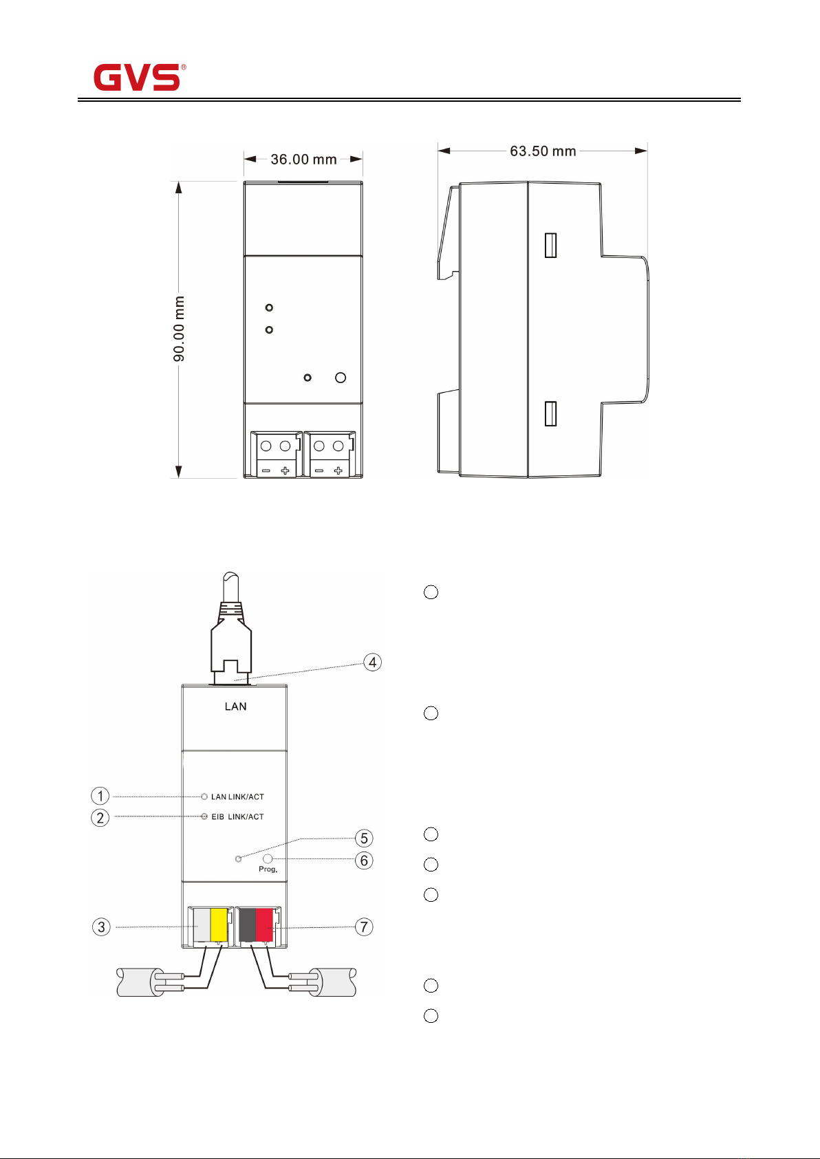
The KNX IP Interface connects the KNX system with the Ethernet network via an Ethernet RJ45
interface in the front ,It serves as an interface between KNX installations and IP networks and can
configure, parameterize and commission the KNX installation as well as bus monitor via the LAN using
the ETS (ETS3 or later) software.
For operation an additional 30V DC supply is necessary. The bus connection and auxiliary power
supply connection are carried out via using KNX bus connection terminals.
The device adopts an Ethernet RJ45 interface to connect with LAN network. The network interface
can be operated with a transmission speed of 10/100Mbit/s Auto Sensing.
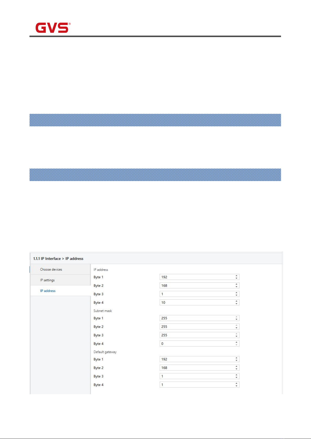
The IP address of the device can be fixed or can be received from a DHCP server. If you need to
remain the IP address static or here no DHCP server on the network, you can assign a fixed IP address
to the device via ETS. The device can program itself and support 5 KNX IP client connections.
The KNX IP Interface is able to use the Engineering Tool Software ETS (ETS3 or later) with a VD4
file to allocate the physical address and set the parameter. The factory default physical addresses are
15.15.255, and the address can be modified directly via local interface settings of ETS.
The KNX IP Interface is a modular installation device. It can be installed in the distribution board on
35mm mounting rails according to EN 60 715.
This manual provides the technical information about the KNX IP Interface as well as assembly and
programming in detail for users, and explains how to use the interface device by the application
examples.

K-BUS®KNX/EIB IP Interface
2
Chapter 2 Technical Data & Dimension and Connection Diagram
2.1 Technical data
Power supply
Operation voltage
21-30V DC, via the KNX bus
Current consumption, bus
<12mA
Power consumption, bus
<360mW
Auxiliary power supply
20-30V DC
Auxiliary power consumption
<2.5W
Connections
KNX
Via bus connection terminal (red/black)
External power supply
Via bus connection terminal (yellow/white)
LAN
RJ45 socket for10/100Base-T, IEEE 802.3
network, Auto Sensing
Operating and
display
Programming LED and button
For assignment of the physical address
Green LED flashing
Indicate the application layer running normally
LAN LINK LED ON
Network connection indicator
LAN LINK LED flashing
Telegram traffic between the device and network
EIB LINK LED ON
KNX bus connection indicator
EIB LINK LED flashing
Telegram traffic between the device and KNX bus
Temperature
Operation
–5 °C ... + 45 °C
Storage
–25 °C ... + 55 °C
Transport
– 25 °C ... + 70 °C
Ambient
Humidity
<93%, except condensation
Design
Modular installation device, on 35mm mounting rail
Dimensions
90 mm×36 mm×64mm
Weight
0.1KG
Housing,
colour
Plastic housing, beige
Application program
Max. number of
communication objects
Max. number of
group address
Max. number of
associations
IP Interface
0
0
0

K-BUS®KNX/EIB IP Interface
3
2.2 Dimension diagram
2.3 Connection diagram
1LAN LINK ON, indicate that network connect
normally
LAN LINK flashing, indicate that telegram traffic is
ongoing. Network activity is indicate by the LED
2EIB LINK ON, indicate that KNX bus connect
normally
EIB LINK flashing, indicate that telegram traffic is
ongoing, which is indicate by the LED
3Auxiliary power supply connection
4LAN connection
5Programming LED, LED red light up for
assignment of physical address, LED green flashes
for application layer running normally
6Programming button
7KNX bus connection terminal

K-BUS®KNX/EIB KNX IP Interface
4
Chapter 3 Parameter setting description in the ETS
3.1 Parameter window “IP settings”
Parameter window “IP setting” is shown in Fig. 3.2.
Because IP Interface and RS485 converter use the same product database, so before setting IP
Interface parameters, you must select devices first, as follow (Fig.3.1):
Fig 3.1 Choose device
Fig.3.2 parameter window “IP settings”
Parameter “Device name (Max. 30 Char.), If first char. = ‘A’ or ‘a’ use DHCP”
The parameter defines the name of the IP Interface to identify the device on the LAN. Here can
entry a maximum of 30 characters in length.
The follow points apply for setting:
If the first character is A or a, the device will work in DHCP mode, and can get an IP address
automatically from network. And the character will not disappear in the device’s name.
If the first character is F or f, the IP address of the device need set by manual. And the character will
not disappear in the device’s name.
For example:
If your device name is “Family”, and you want to use DHCP mode, Input string “AFamily”. If you
want to use Fix mode, Input string “FFamily.

K-BUS®KNX/EIB IP Interface
5
If your device name is “Audio”, and you want to use DHCP mode, Input string is “AAudio”. If you
want to use Fix mode, Input string is “FAudio”. If you input “Audio”, then the device name is “udio”, and
use DHCP mode.
If your device name is start with another character, you can input the device name directly, with Fix
IP address mode, without with the “F” or “f” start. If you want to use DHCP mode, you only add “A” or “a”
at ahead of your device name.
Parameter “IP address assignment (Don’t use it if DHCP)”
The parameter indicates that the IP address assignment of the Interface is fixed if the DHCP mode
is not used.
If the DHCP mode is used, the parameter is invalid.
The fixed IP address can be assigned in the follow parameter window “IP address”, see fig. 3.3.
Parameter “If you use private protocol, the port is”
The parameter is not used.
3.2 Parameter window “IP address”
Parameter window “IP address” is shown in fig. 3.3. Here set network connection information, such
as IP address, Subnet mask and Default gateway.
If the IP Interface use DHCP mode, the parameters are invalid in the window.
Fig 3.3 parameter window “IP address”

K-BUS®KNX/EIB IP Interface
6
Parameter “IP address”
The parameter defines the IP address of the IP Interface, the IP address is unique on the LAN, to
avoid collide. Option: Byte x: 0…255
The IP address should be entered in a byte-by-byte manner, e.g. as follows for address
192.168.1.10:
Byte1: 192
Byte2: 168
Byte3: 1
Byte4: 10
Parameter “Subnet mask”
The parameter defines the subnet mask of the IP Interface. The subnet mask must be set to reflect
the number and structure of the subnet. Option: Byte x: 0…255
In a small network the subnet mask 255.255.255.0 should be set as follows:
Byte1: 255
Byte2: 255
Byte3: 255
Byte4: 0
Parameter “default gateway”
The parameter defines the default gateway. The default gateway must be the same network
segment with the IP address. Option: Byte x: 0…255
The default gateway 192.168.1.1 should be set as follows:
Byte1: 192
Byte2: 168
Byte3: 1
Byte4: 1
Other manuals for K-BUS BNIP-00
1
This manual suits for next models
1
Table of contents
Other GVS Recording Equipment manuals
Popular Recording Equipment manuals by other brands

Toshiba
Toshiba HWS-IFAIP01U-E 0-10V installation manual

Tascam
Tascam US-122 supplementary guide

Honeywell
Honeywell IF-LON2 Product Manual and Mounting Instructions

TC-Helicon
TC-Helicon VoiceWorksPlus user manual

Dover
Dover markem-imaje SmartDate 5 Maintenance manual

Fred’s Lab
Fred’s Lab Buzzzy User and service manual