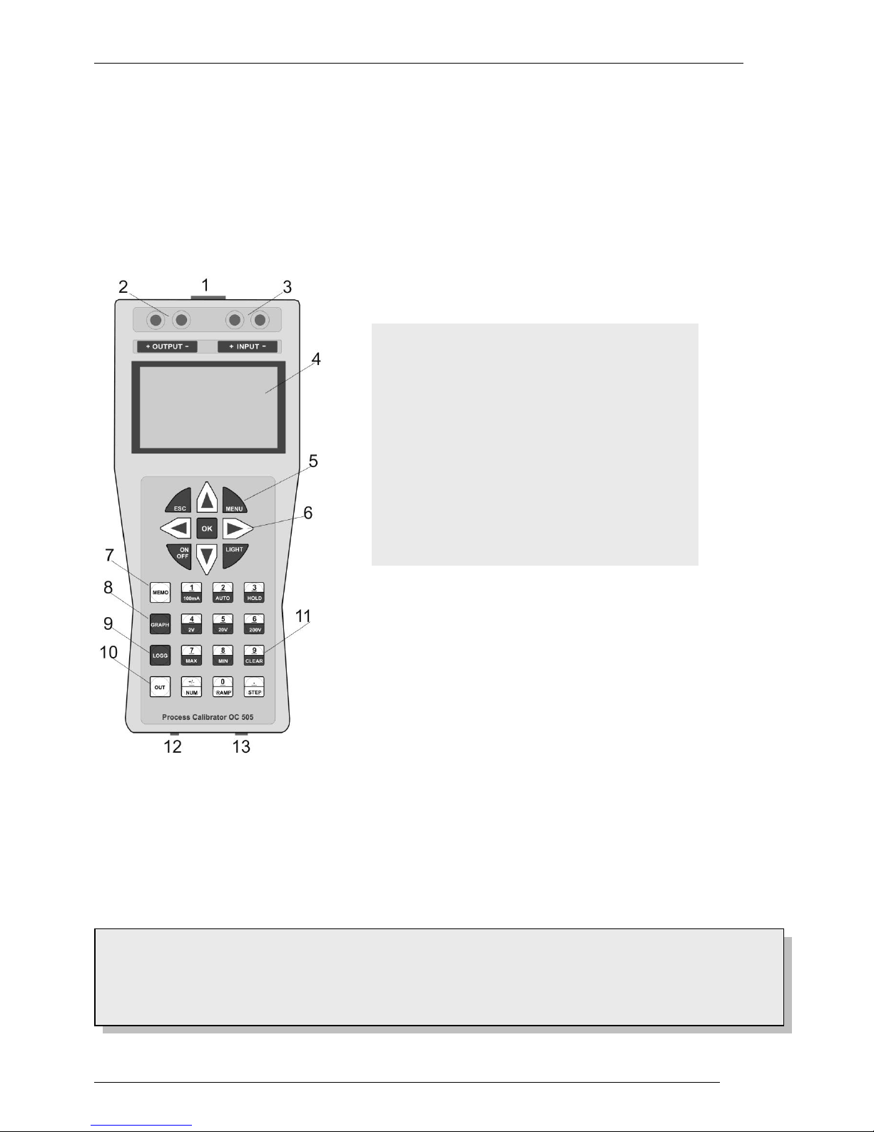
Meatest M505D User manual

M505 (D) Process calibrator
Operation manual


MEATEST, s.r.o. Process Calibrator M505
1 version 7 Operation manual
Content
1INTRODUCTION ...............................................................................................................................2
2UNPACKING INSTRUCTIONS.......................................................................................................3
3INPUTS, OUTPUTS and KEYBOARD............................................................................................4
4GRAPHICS DISPLAY........................................................................................................................5
5DATALOGGER (Software Option) ..................................................................................................5
6FUNCTION SELECTION - CALIBRATOR...................................................................................6
7GRAPHICS..........................................................................................................................................8
7.1 GRAPHICS....................................................................................................................................8
7.2 TRANSIENTS................................................................................................................................8
8MENU STEPS......................................................................................................................................9
9ADDITIONAL FUNCTIONS in the MULTIMETER MODE .....................................................10
10 SOFTWARE - CALIBRATION ......................................................................................................10
10.1 CALIBRATION of CALIBRATOR OUTPUTS..........................................................................11
10.1.1 Calibration of Currents ........................................................................................................11
10.1.2 Calibration of Voltages.........................................................................................................11
10.1.3 Calibration of Resistances....................................................................................................12
10.2 CALIBRATION MULTIMETER .....................................................................................12
11 DATALOGGER ................................................................................................................................13
12 SOFTMANAGER M505W...............................................................................................................14
13 SPECIFICATION..............................................................................................................................18
13.1 CALIBRATOR .............................................................................................................................18
13.2 MULTIMETER............................................................................................................................19

Process Calibrator M505 (D) MEATEST, s.r.o.
Operation manual v7 2
1 Introduction
Current Calibrator 0/4 - 22mA, Source/Sink
Voltage Calibrator 0-25V
mV Outputs 0-27mV and 0-540 mV
DIN Thermocouples J, K, N, R, S, T, B, E
RTD Simulator Pt and Ni
Resistance Simulation to 3kOhm
Multimeter ±2V to ±200V DC and +100mA
Calibrates and Measures Simultaneously
Eight Memory slots for fast Transients
Graphics of Measurements
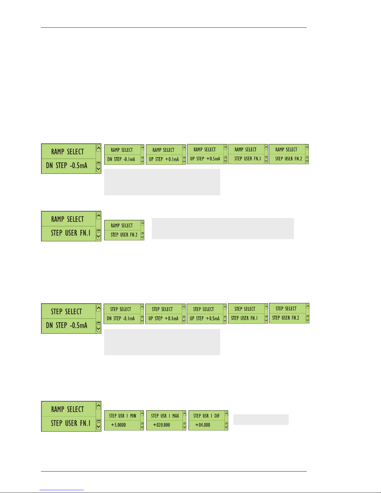
Steps, Ramps, direct value settings
Datalogger Function in M505 D model
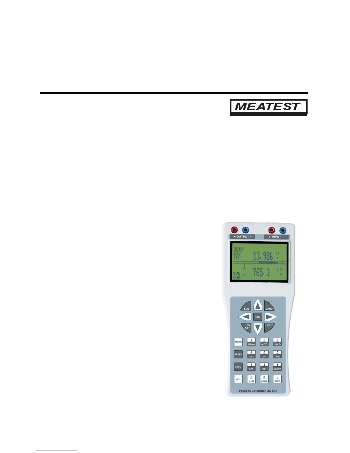
M505 is a Calibrator-Multimeter for generation of Currents 0-22mA Sink or
Source und Voltages to 25VDC. External voltages ±2V, ±20V and ±200VDC
(firm ranges or auto ranging) and Currents to ±100mA can be measured
simultaneously and shown at the display.
Further Functions contain generation of calibration mV Signals, Thermo voltages of DIN Thermocouples and RTD
Resistors and simulation of true resistors.
mV voltages of 0-27mV or 0-540mV are mainly used for calibration of Strain Gauges, Transmitters and small
signal inputs with resolution of up to 0.001mV.
Thermocouples J, K, N, R, S, T, B, E are simulated. The temperature is entered with the keyboard and shown at the
display. The cold junction is compensated to the ambient temperature. It can also be switched-off.
RTD Thermometers can be simulated within the DIN temperature range. The temperature is entered with the
keyboard and shown at the display.
Ohm Source Resistance values up to 3kOhm are simulated. The resistance value is entered with the keyboard and
shown at the display.
Graphics and Memorising of measured signals is a standard function. The signals are continuously stored and
shown at the display as graphics. In apart of this eight memory slots for storing of fast signals -Transients- are
available. They can individually be stored and selectively recalled at the display.
Datalogger is an Option. The calibrating signals and the multimeter input are shown at the display and stored as
tables with date and time from internal RTC. They can be downloaded to the PC and edited under Windows and
Excel. A software program is available for Windows.

Process Calibrator M505 (D) MEATEST, s.r.o.
3 Operation manual v6
2 Unpacking Instructions
Remove the Packing List and verify that you have received all equipment, including the following:
- Model M505 Handheld Calibrator.
- Operation Manual M505.
If you have any questions about the shipment, please call the Meatest Customer Service.
Content of delivery
- Calibrator-Multimeter Model M505 (D)
- Charger 95-240VAC
- Two signal cables
- T/C plug K, U
- SoftManager for Windows
- Operation Manual and Calibration Certificate
NOTE
When you receive the shipment, inspect the container and equipment for signs of damage. Note
any evidence of rough handling in transit. Immediately report any damage to the Meatest customer
service, Phone +420 543 250 886 or Fax +420 543 250 890 and to the shipping agent.
The carrier will not honour damage claims unless all shipping material is saved for inspection. After
examining and removing contents, save packing material and carton in event the reshipment is
necessary.

Process Calibrator M505 (D) MEATEST, s.r.o.
Operation manual v7 4
3 Inputs, Outputs and keyboard
CALIBRATOR
Voltage and Current Outputs,
Resistance and RTD: + OUTPUT -
Thermocouples: Cu Terminals at the front
MULTIMETER
Voltage and Current Inputs: + INPUT -
CONTROLLER
The Functions of the Calibrator and the Multimeter are selected with the keyboard and supported by a
microcontroller. The factory settings and the calibrated points are stored in a nopn-volatile memory and remain
stored also when the instrument is switched off. The software calibration of all ranges is accessible in the
calibration menu and protected with a password. All ranges can be recalibrated via the keyboard if required.
The graphic display is divided into two windows. The upper window is shows the multimeter functions, the lower
window the calibrator. In programming mode the display shows the parameters. In graphics mode of operation the
display shows the stored input signals.
The Multimeter is always active and can be used independently from the calibrator. The ranges can be selected
with the keyboard. The current range is firm. The voltage ranges are firm 2V, 20V or 200VDC or can be set as
automatic range.
Minus Terminals of the Calibrator and the Multimeter are common.
1 Thermocouples Connector
2 Output Calibrator
3 Input Multimeter
4 LCD-Display
5 Main Keys
6 Cursor Keys
7 Memory Key
8 Recall Graphics
9 Datalogger
10 Selection of Calibrator Output Mode
11 Function Keys
12 Charger Jack
13 USB

Process Calibrator M505 (D) MEATEST, s.r.o.
5 Operation manual v6
4 Graphics display
The LCD Display is divided into two parts. The upper part is for the multimeter functions, the lower part for the
calibrator. The bargraph in the middle is the analogical representation of the measured input signals. The left side
shows various symbols:
Symbols in the upper display part
AUTO Automatic Voltage Range or firm measuring range
200V Measure Ranges 2V, 20V, 200V, 100mA
INP The display shows the input signal.
Symbols in the lower display part
RMP Automatic Ramp of the calibrator signal
SUP The battery is being charged
60% Battery voltage in %. Do not run the instrument when the battery shows 0%. Charge only with the
enclosed original charger.
5 Datalogger (Software Option)
The generated signal and the measured signal are stored in a table format. The date and the time are added. The
stored data can be downloaded via the USB to a PC. A Soft Manager supports the data transfer to a Windows PC.
Two Set Points LEVEL LOW and LEVEL HIGH and two Intervals INTERVAL 1 and INTERVAL 2 will be
selected. If the measured signal is between the both Set Points LEVEL LOW and LEVEL HIGH, the data will be
stored with INTERVAL 1. The INTERVAL 2 stores the date when the input signal is outside the Set Points. The
both Intervals can be selected from 2 sec. to 24 hours.
With the key LOGG is the function Datalogger active. The key MENU and the two cursor keys permit the
parameter selection. With OK the setting will be stored.
MULTIMETER measured input voltage in
automatic range.
CALIBRATOR generates 12.000mA. The Battery
has 70% of capacity.
LOGGER OFF Datalogger OFF
LOGGER ON Data are stored
MEMORY ERASE Erase the memory
INTERVAL 1: < 2 Sek. … 24 Std.
INTERVAL 2: < 2 Sek. … 24 Std.
LEVEL LOW: free settable
LEVEL HIGH: free settable

Process Calibrator M505 (D) MEATEST, s.r.o.
Operation manual v7 6
6 Function selection –calibrator
The calibrator function is selectable with the keys. The output values can be set in steps, ramps or free values.
The output function will be selected with OUT. Vertical cursor keys select the required function:
Current Source 0 - 22mA
Current Sink 0 - 22mA
Voltage Output 0 - 25V
Voltage Output 0 - 560mV
Voltage Output 0 - 28mV
Resistance Output 45 - 3000 Ohm
RTD Outputs Pt-100, Pt-200, Pt-500,
Pt-1000, Ni 1000
Simulation of Thermocouples
B, J, K, N, R, S, T
OK confirms the selection. The selected function remains memorised also when the power is switched-off.

Process Calibrator M505 (D) MEATEST, s.r.o.
7 Operation manual v6
DIRECT VALUE ENTRY
When the key NUM is pressed, the display shows the previous value with flashing digit. This digit can be set from
the keyboard. The flashing digit will be positioned automatically. It can also be positioned with the horizontal
cursors.
RAMPS
The key RAMP activates the Ramp generation. The values at the display increment in steps selected in the Menu.
The display shows the symbol RMP.
By pressing the key RAMP again, the ramp generation will stop.
Ramp Steps selection in MENU
Press MENU. The step can be selected from firmly pre-programmed values with the vertical cursors. Confirm with
OK.
RAMP STEPS
With keys RAMP or STEP the display will increment in steps selected in the MENU.
Selection of Steps in the MENU
Press the key MENU. Use the vertical cursors to select the Step from pre-programmed values. Confirm with OK.
Selection of individual Steps
The range and the steps can be set in two memory slots FN.1 and FN.2.
Press MENU and select RAMP SELECT. With the key MENU and vertical cursors select the range and the steps.
Confirm with OK.
Example: Current Output 0 - 22mA
DN STEP: Display decrementing
UP STEP: Display incrementing
Individual Ramp Step scan be selected und stored
in FN.1 and FN.2.
Example: Current Output 0 - 22mA
DN STEP: Display decrementing
UP STEP: Display incrementing

Process Calibrator M505 (D) MEATEST, s.r.o.
Operation manual v7 8
7 Graphics
For fast diagnostics of external signals measured by the multimeter the graphics representation can be displayed.
Two modes of operation are available:
- GRAPHICS the running measurement is automatically stored in 128 points (FI-FO)
- TRANSIENTS Eight individual memory slots are assigned for fast signals –Transients.
The sampling time and the Trigger level are selectable.
The Memory module for the Graphics and the Transients are common. By recalling the Transients, the Graphics
will be erased.
7.1 GRAPHICS
The key GRAPH opens the graphic presentation.
Graphics deactivated - GRAPH OFF. The graphics can be activated with vertical cursors - GRAPH ON.
The latest stored signal will be displayed when OK is pressed.
7.2 TRANSIENTS
Fast signals at the multimeter input can be stored. Eight individual memory slots TRANSIENT NO.1 …
TRANSIENT NO.8 are available. The sampling rate is 1ms. Each transient contains 256 Point and can be time
limited from 0.25 to 300 seconds. The Trigger level is programmable from <10% to >90%.
With the key MENU the Transients can be stored or recalled at the display. The selection is done with the vertical
cursors.
The parameters will be selected with the key MENU:
Stored Transient 1 is shown at the display
Transient 1 deleted
The key MENU and vertical cursors select
the time
The key MENU and vertical cursors select
the Trigger level
The graphics at the display
Start of Transient 1
memorizing
0.25 … 300 sec.
<10% … >90%

Process Calibrator M505 (D) MEATEST, s.r.o.
9 Operation manual v6
8 Menu steps
When the key MENU is used in the measuring mode, the display will change into program mode.
Ramp and step selection
Step selection
Individual step, minimum value, User 1
Individual step, maximum value, User 1
Individual step, differential value, User 1
Individual step, minimum value, User 2
Individual step, maximum value, User 2
Individual step, differential value, User 2
Junction compensation ON - OFF
Temperature units ºC or ºF
Tare of the Multimeter display ON - OFF
Filter constant of the Multimeter display
Setting of the Time and the Date
Software Upgrade OFF - ACTIVE
With ESC one return step in Menu is possible. By pressing ESC three times, the display returns
into the measuring mode.

Process Calibrator M505 (D) MEATEST, s.r.o.
Operation manual v7 10
9 Additional functions in the multimeter mode
The key MENU opens the Functions TARA and FILTER for the Multimeter:
ADDITIONAL FUNCTIONS
The numeric keyboard permits selection of following functions:
HOLD Display Hold (with CLEAR return)
MAX Maximum display reading of the Multimeter (with CLEAR return)
MIN Minimum display reading of the Multimeter (with CLEAR return)
CLEAR Cancel the above functions and switches into the measuring mode
10 Software –calibration
The voltage and the current ranges of the multimeter as well as the output signals of the calibrator can be calibrated
from the keyboard. The calibration menu is password protected. The calibration menu opens with the key OK
pressed for 10 seconds.
Full calibration of all ranges or partial calibration of some selected ranges can be performed. A precision 5 digits
multimeter with accuracy of 0.005% is required.
Point 1:Calibrator Outputs
Points 2-3: Multimeter Inputs
Point 4:Calibration of the Resistor Simulator
Point 5:Hardware Configuration
Point 6:Selection of Logo for customized instrument
Quit the Menu with ESC.
Please ask the manufacturer for the Password.
The TARE can be activated
The Filter can be set for the input signal.

Process Calibrator M505 (D) MEATEST, s.r.o.
11 Operation manual v6
10.1 CALIBRATION of CALIBRATOR OUTPUTS
Select the required range (1) or (4).
Currents, Voltage, Resistors and Thermocouples will be calibrated in the Range (1).
In the Range (2) the Resistors and the RTD will be calibrated.
10.1.1 Calibration of Currents
Connect a mA-Meter to the calibrator outputs. Required accuracy 0.01% @ 25mADC
10.1.2 Calibration of Voltages
Connect V-Meter to the calibrator outputs. Required accuracy 0.01% @ 25VDC
Set the value with the keyboard until the connected mA-Meter
shows 4.000 mA. SOURCE MODUS.
Set the value with the keyboard until the connected mA-Meter
shows 20.000 mA. SOURCE MODUS.
Set the value with the keyboard until the connected mA-Meter
shows 4.000 mA. SINK MODUS.
Set the value with the keyboard until the connected mA-Meter
shows 20.000 mA. SINK MODUS.
Set the value with the keyboard until the connected V-Meter
shows 0.000 V.
Set the value with the keyboard until the connected V-Meter
shows 24.000 V.
Set the value with the keyboard until the connected V-Meter
shows 0.000 mV.
Set the value with the keyboard until the connected V-Meter
shows 500.000 mV.
Set the value with the keyboard until the connected V-Meter
shows 0.000 mV.
Set the value with the keyboard until the connected V-Meter
shows 25.000 mV.

Process Calibrator M505 (D) MEATEST, s.r.o.
Operation manual v7 12
10.1.3 Calibration of Resistances
Connect Ohm-Meter to the calibrator outputs. The required accuracy is 0.05%.
10.2 CALIBRATION MULTIMETER
Select the required range (2) or (3).
The Range (2) is for calibration of the current, the Range (3) is for the voltage calibration.
Set with the keyboard the resistance value which is being
measured with the connected Ohm-Meter.
Set with the keyboard the resistance value which is being
measured with the connected Ohm-Meter.
Set with the keyboard the resistance value which is being
measured with the connected Ohm-Meter.
Set with the keyboard the resistance value which is being
measured with the connected Ohm-Meter.
Supply from external current calibrator 0.000 mA and confirm with
OK. The point 0.00A is calibrated.
Supply from external current calibrator 100.000 mA and confirm
with OK. The point 0.1A is calibrated.
Supply from external voltage calibrator 0.000 V and confirm with
OK. The point 0V is calibrated.
Supply from external voltage calibrator 2.000 V and confirm with
OK. The point 2V is calibrated
Supply from external voltage calibrator 20.000 V and confirm with
OK. The point 20V is calibrated.
Supply from external voltage calibrator 0.000 V and confirm with
OK. The point 0V is calibrated.
Supply from external voltage calibrator 0.000 V and confirm with
OK. The point 0V is calibrated.
.
Supply from external voltage calibrator 200.000 V and confirm with
OK. The point 200V is calibrated.

Process Calibrator M505 (D) MEATEST, s.r.o.
13 Operation manual v6
The key ESC terminates the calibration and the display returns into the measuring mode.
11 Datalogger (model M505D only)
When the function Datalogger is activated, the calibrator output and the multimeter input signals will be stored in
the internal memory. This permits fast checking of transmitters and their calibration in the field.
Example: A T/C transmitter with mV input signal generates 0-10V at the output. Both signals are stored as a table
with date and time added from internal RTC.
The Data can be downloaded to the PC and displayed as tables and graphics. They can be used for Excel and
handled under Windows.
Set Points LEVEL LOW and LEVEL HIGH and Intervals INTERVAL 1 and INTERVAL 2 will be selected. If
the measured signal is within the set points LEVEL LOW and LEVEL HIGH, the data will be stored with
INTERVAL 1. Outside the set points the Data are stored with INTERVAL 2. The Intervals are programmable
from 2 seconds to 24 hours.
DATA STORE
After LEVEL LOW and LEVEL HIGH and INTERVAL 1 and INTERVAL 2 are set, the data logging can be
initiated with LOGGER ON and OK.
In the menu step LOGGER OFF is the logging terminated.
The key MENU and the vertical cursors permit the selection of the parameters. They will be stored with the key
OK.
RECAL of stored DATA
The stored data can be uploaded to the PC via USB terminal. Enclosed Softmanager M505W supports the
communication.
Apart of the stored data, also the Transients cane be uploaded to the PC (see 5.2) and displayed as tables and
graphics and handled under Windows and Excel.
LOGGER OFF Data logging disabled
LOGGER ON Data logging enabled
MEMORY ERASE Stored data will be erased
INTERVAL 1: < 2 sec … 24 h
INTERVAL 2: < 2 sec … 24 h
LEVEL LOW: free selectable
LEVEL HIGH: free selectable

Process Calibrator M505 (D) MEATEST, s.r.o.
Operation manual v7 14
12 Softmanager M505W
The Softmanager M505W permits an upload of the stored data and the transients to a PC, displaying the results in
tables and graphics and handling under Windows and Excel.
M505 Calibrator will be connected via USB to a PC and switched-on.
The Softmanager M505W will be installed at the PC and opened. The window shows the selection:
COM Selection
COM The data port will be automatically found with Find COM.
The Lamp changes the colour to green when the communication is running.
Assure the speed of the PC COM to run at high Baud Rate.

Process Calibrator M505 (D) MEATEST, s.r.o.
15 Operation manual v6
Logger Table The stored data in M505 are transferred to the PC with Upload. They appear in
selected units in a table format with date and time added from internal RTC.
When the calibrator signal sent to the transmitter under test is e.g. 0-22mA and
the transmitter output is a current, the transmitter signal has to be measured at the
multimeter input 100mA.
Stop Communication stops.
Save The data are stored in a Text Format *.txt or Excel Format *.xls.
Copy Copy the data.

Process Calibrator M505 (D) MEATEST, s.r.o.
Operation manual v7 16
Transient Data Table
Number Eight memory slots for fast signals at the multimeter input. Each Transient contains
256 samples, selectable Sampling Time and selectable Trigger Level (see 5.2).
Upload The selected Transiente will be transferred to the PC with Upload.
Save The data are stored in a Text Format *.txt or Excel Format *.xls.
Copy Copy the data.

Process Calibrator M505 (D) MEATEST, s.r.o.
17 Operation manual v6
Transient Graphics
The selected Transient appears as Graphics, with Time Base, Scale, Date and Time.

Process Calibrator M505 (D) MEATEST, s.r.o.
Operation manual v7 18
13 Specification
13.1 CALIBRATOR
Voltage and Current: + OUTPUT –
Thermocouples: Cu Connector
Current Source Range 0 ... 22mA. Maximum external Shunt 750 Ohm
Accuracy ± (0.05% from Value + 0.1% from Range)
Resolution 0.001 mA
Current Sink Range 0 ... 22mA at 24V maximum
Accuracy ± (0.05% from Value + 0.1% from Range)
Resolution 0.001 mA
Voltage Source Range 0 ... 25 V, 0 … 540mV, 0 … 27mV
Accuracy ± (0.05% from Value + 0.1% from Range)
Resolution: 0…25.000V, 0…560.00mV, 0…28.000mV
Thermocouples According to DIN:
J (1200 ºC), K (1370 ºC), N (1300 ºC), R (1760 ºC),
S (1760 ºC), T (400 ºC), B (1820 ºC), E (1000 ºC).
Accuracy ± 0.5 - 2 ºC
Resolution 0.1ºC
RTD Thermometer Pt-100, 200, 500 -140 ºC to 850 ºC, max. Load 0.1W.
Pt-1000 -140 ºC to 550 ºC, max. Load 0.1W.
Accuracy ± 0.1% from Value ± 1 ºC
Pt-1000 550 ºC to 850 ºC, max. Load 0.1W.
Accuracy ± 0.2% from Value ± 1 ºC
Ni - 1000 -60 ºC to 170 ºC max. Load 0.1W
Accuracy ± 0.1% from Value ± 0.5 ºC
Resolution 0.5 ºC
Resistors 45 Ohms to 2000 Ohm, maximum load 0.1W
Accuracy ± 0.1% from Value ± 0.5 Ohm
2000 Ohms to 3000 Ohm, maximum load 0.1W
Accuracy ± 0.2% from Value ± 0.5 Ohm
Resolution 0.1 Ohm
Tempco 25ppm/K
Temperature Working: -10 ºC ... +35 ºC, Storing: 0 ... 60 ºC
Reference: 23 ºC ± 5 ºC
Terminals 4mm plugs, gold plated, compensated Cu Terminals for thermocouples
Supply Two rechargeable Li-Ion Batteries 3.7V-2000mAh.
Battery operation approx. 8 h with backlight switched-off
Charger Mains Voltage100-240V, 48-60Hz / 12V-600mA DC.
Charging time 4 hours. The batteries are fully charged when the green LED
illuminates continuously.
Cabinet Dimensions 200 x 90 x 40mm (L x W x D), weight 320 g
All specifications are valid after a warm-up time of 10 minutes at an ambient temperature of 23 ºC ± 5 ºC.
This manual suits for next models
1
Table of contents
Other Meatest Test Equipment manuals

Meatest
Meatest 9010 User manual

Meatest
Meatest 9010+ User manual

Meatest
Meatest M525 User manual

Meatest
Meatest M-140 User manual

Meatest
Meatest M143 User manual

Meatest
Meatest M133C User manual

Meatest
Meatest M-142 Installation manual

Meatest
Meatest M631 User manual

Meatest
Meatest M133C User manual

Meatest
Meatest MC641 User manual